


SWRU337
March 2013
Web sites:
www.ti.com/lprf
E2E Forum:
www.ti.com/lprf-forum
Make sure to subscribe to the Low-Power RF
Newsletter to receive information about updates to
documentation, new product releases, and more.
Sign up on the TI web pages.
CC1200 Evaluation Module Kit Quick Start Guide
Opening the Box and Running the Packet Error Rate Test
1. Kit Contents
2 x CC1200 Evaluation Modules
2 x Antennas (type depending on frequency)
The EMK is an add-on kit to supplement the
CC1200DK with evaluation boards supporting
additional frequency bands. This document
covers the CC1200EMK.
The 868-930 MHz RF boards in this kit are FCC
and IC certified and both 868-930 MHz and 420-
470 MHz RF boards are tested to comply with
ETSI/R&TTE over temperatures from 0 to +35°C.
The W5017 whip antenna from Pulse has a gain
of 2 dBi and the SPWH24433TI whip antenna
from Pulse has a gain of 0 dBi.
Antenna types:
868-930 MHz:
Pulse W5017
420-470 MHz:
Pulse SPWH24433TI
2. How to use the Modules
The CC1200EM boards can be plugged into
several
development
boards
from
Texas
Instruments. Most notably, you can use the
SmartRF Transceiver EB, which is included in
the CC1200DK. This board lets you run a packet
error rate (PER) test, control the device from
SmartRF™ Studio and it can be used as a
development platform.
It is also possible to connect the EM to other TI
development
boards
with
the
appropriate
connectors or to the basic “SoC Battery Board”.
The latter can be used as a carrier board for the
EM to simplify the connection to other boards
with a microcontroller. See:
This guide will show how to use the modules
together with SmartRF Transceiver EB (TrxEB).
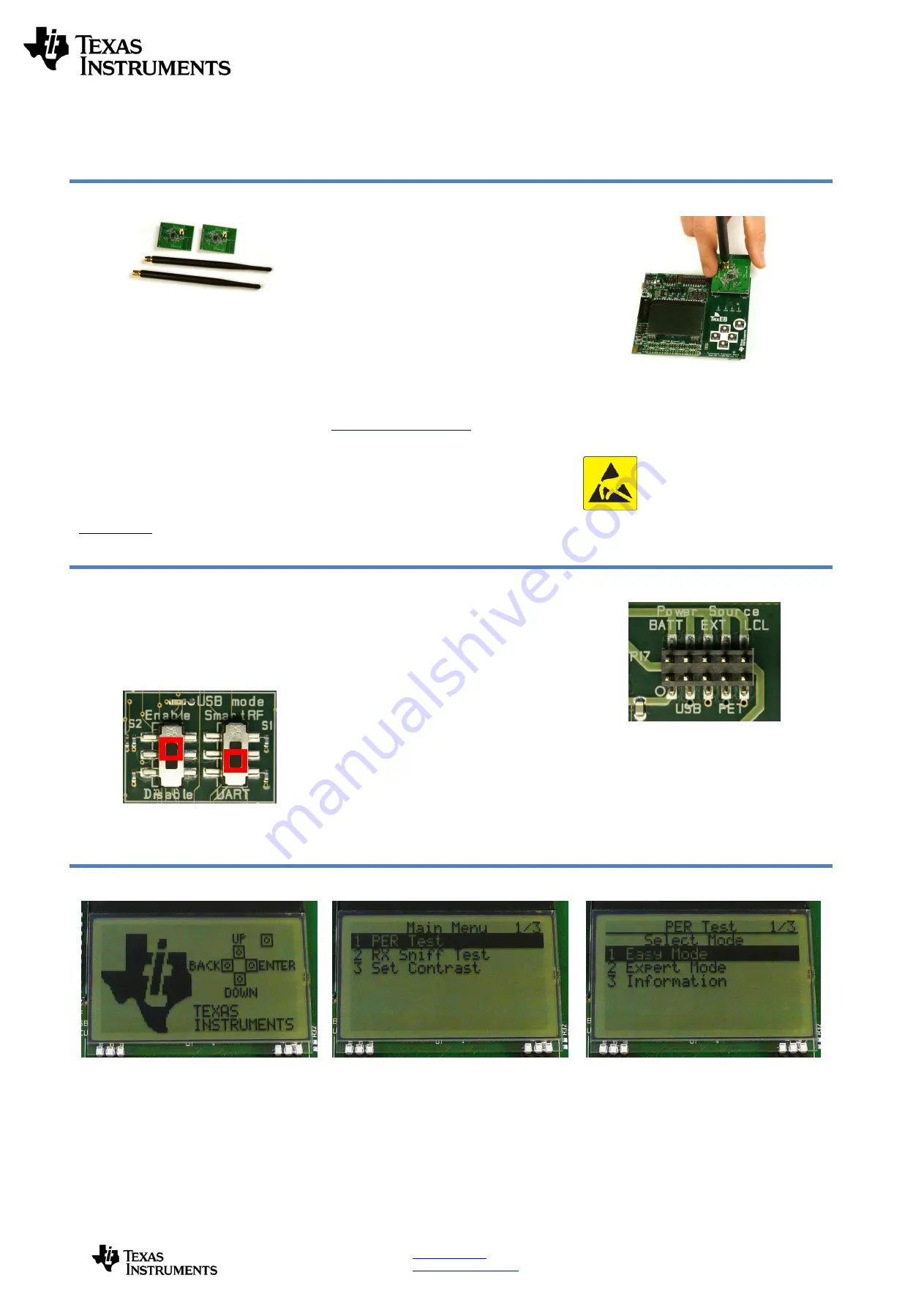
3. Plug the EM into the TrxEB
Insert a CC1200EM into the TrxEB. The
connectors will only fit in one position so that the
EM cannot be inserted the wrong way. Do not
use excessive force on the EM. Remember to
mount the antenna.
Caution!
The kit contains ESD sensitive
components. Handle with care to
prevent
permanent
damage.
To
minimize risk of injury, avoid touching
components
during
operation
if
symbolized as hot.
4. Select Board Mode
Use the switches S1 and S2 to select the
operating mode of the board. For the sake of this
quick start guide, please select “Enable” and
“UART”. This configuration will make it possible
to communicate directly with the MSP430 over a
virtual COM port on the PC.
5. Power Options
There are several ways of applying power to the
TrxEB.
2 x 1.5 V AA batteries
USB
External Power Supply
MSP430 Debugger
For the batteries and USB, there are voltage
regulators on the TrxEB that will set the on-board
voltage to 3.3 V. The external power supply
should set a voltage that does not exceed 3.3 V.
By default, the MSP430 debugger supplies 3.0 V.
Note that there should only be one active
power source at any one time.
Warning!
To minimize risk of personal injury or
property damage, never use rechargeable
batteries to power the board. Do not leave the
EVM powered when unattended.
6. Select Power Source
Depending on the power source, make sure
you connect jumpers to the appropriate pins
on the “Power Source” header. For instance,
if you use batteries, use a jumper to short-
circuit pin 1 and 2 on the header. The last
jumper in the row (pin 9-10) should always
be mounted, unless the MSP430 FET is
used as the power source.
7. Welcome Screen
Turn on power with the Main Power switch. You
should now see the Texas Instruments logo and
a short description of the buttons on the LCD.
Pushing any of the five buttons on the board will
take you to the main menu.
NB! If you don’t see anything on the screen
make sure the mode switches are in the
correct positions (see step 4 above).
.
8. Packet Error Rate Test
Select the PER (Packet Error Rate) test by
highlighting the selection using the up/down
buttons. Confirm your selection by pressing
Enter (right button).
9. Select Test Mode
The PER test can be run is several modes. Easy
Mode sets up a one-way test and uses default
settings. This test is convenient for practical
range testing.
The other test modes are described in the
“
TrxEB RF PER Test Software Example
User’s
Guide
”.
To proceed, h
ighlight “Easy Mode” and press
Enter (right button).