SWRU234b
October 2012
CC1110 Mini Development Kit 868-915 MHz
Quick Start Guide
1 Kit Contents
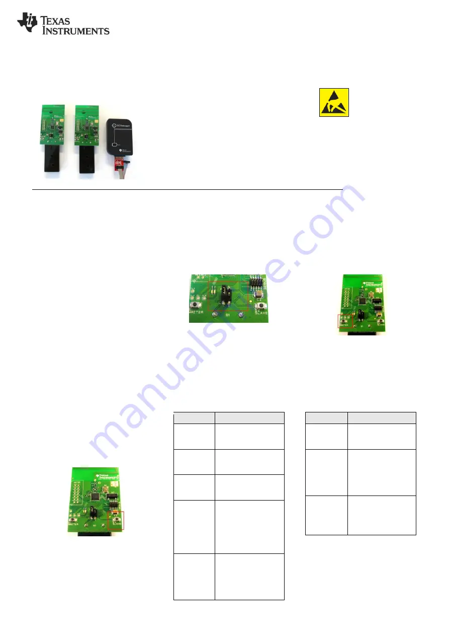
2 x SmartRFCC1110-868 target boards
1 x CC Debugger
1 x 10- pin flat cable with 2x5 2.54 mm connector
1 x 10-pin flat cable with 2x5 1.27 mm connector
1 x Converter board 2.54 mm
– 1.27 mm connector
1 x Mini USB cable
Batteries
CD with Evaluation Version of the IAR EW8051
Documentation
The hardware in this kit is FCC/IC certified and complies with ETSI/R&TTE over temperature from 0 to +35°C.
2 Running the Preprogrammed Link Test
2.1 Introduction
The CC1110 on the SmartRFCC1110 target
board is preprogrammed with a link test which
operates at 868.3 MHz, and uses GFSK
modulation and a bit rate of 2.4 kbps.
The link test runs a point-to-point communication
between a Slave and a Master node based on
the SimpliciTI 1.1.0 protocol.
First the Master and Slave nodes must be
configured as described in the following
sections. The two nodes will then establish a
link. When this link is established, the Master
starts to periodically send packets to the Slave.
Between each transmission, the Master goes to
receive mode and waits 250 ms for an
acknowledgement packet from the Slave. The
Slave node is in receive mode waiting for
packets from the Master. For each received
packet, the Slave automatically responds with
an acknowledgement packet.
2.2 Powering the boards
Place 2 AAA batteries in the battery holders
placed on the bottom side of each of the
SmartRFCC1110-868 boards. Place the jumper
on the power selection connector P1 between
pin 1 and pin 2 on each board.
Applying power to the SmartRFCC1110-868
starts the preprogrammed link test on the
CC1110 and the two LEDs on the board are on
for 1 s.
Warning! To minimize risk of personal
injury or property damage, never use
rechargeable batteries to power the board.
Do not leave the board powered when
unattended.
2.3 Configure the Master Node
Press the S1/MASTER button that is placed on
the left hand side of the board. When this
button is pushed, the two LEDs on this board
will blink rapidly. The Master now waits for a
Slave node to establish a link.
Note that the boards only respond to the first
button push. To reconfigure the board, the
board must be reset, see point 2.9 in this
manual.
2.4 Configure the Slave Node
On the other board, press the S2/SLAVE button
that is placed on the right side of the board.
When the button has been pushed, the two
LEDs on this board will blink very slowly until a
link with a Master node is established. Note that
establishing the link may finish in less than 1 s
depending on the environment.
It is important to keep distance (more than 1
meter) between the two nodes when they are
trying to establish the link to avoid saturation.
This is because full output power (12 dBm) is
used for this communication between the nodes.
2.5 The LEDs on the Master Node
LEDs
State
Both
LEDs
blink rapidly
The Master is trying to
establish a link with a
Slave
Green
LED
on for 0.5 s
The
Master
has
received an ACK to a
packet sent, link ok
Red LED on
for 0.5 s
The Master has not
received an ACK to the
last 3 packets sent
Red LED on
for 3 s
If the Master does not
receive ACKs from the
SLAVE in ~70 s, the
Master will stop to send
packets to save power.
Press S1/MASTER to
resume the link test
Red LED on
for 5 s
For test only:
When
the
link
is
established,
pressing
the S2/SLAVE button
turns the red LED on for
5 s
2.6 The LEDs on the Slave node
LEDs
State
Both
LEDs
blink slowly
The Slave is trying to
establish a link with a
Master
Red LED on
continuously
The link between the
Slave and Master is
established
and
the
Slave is in RX waiting
for packets from the
Master
Green LED
on for 0.5 s
while red LED
on
continuously
The Slave has received
a
packet
from
the
Master and sent an
ACK, link ok
Caution!
The kit contains ESD
sensitive components. Handle
with care to prevent permanent
damage. To minimize risk of
injury,
avoid
touching
components during operation if
symbolized as hot.


