


SWRU126B
April 2010
CC1101DK Quick Start Guide
Opening the box and running the Packet Error Rate Test
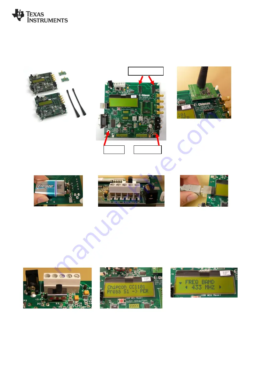
1. Kit Contents
2 x SmartRF04EB
2 x CC1101EM
2 x Antennas (433 MHz antennas shown)
2 x USB cables
4 x SMA male to BNC female converters
Documentation
2. SmartRF04EB Overview
3. Plug EM into SmartRF04EB
Insert a CC1101EM (EM) with an antenna
into the SmartRF04EB (EB). The
connectors will only fit in one position, so
that the EM cannot be inserted the wrong
way.
Handle the EM with care. Observe
precautions for handling electrostatic
sensitive devices.
4a. Power: Battery
There are three different ways of applying
power to the EB:
The first method involves using a battery,
for instance a 9V battery (not included in
the kit) connected to the connector on the
bottom side of the board.
4b. Power: DC/External
The second method applies DC power
using the DC input jack (right in picture,
centre is +, sleeve is ground), or by
connecting a 4-10V voltage source
between the 4-10V and 0V terminals of the
power connector (left in picture). It is also
possible to connect a 3.3V voltage source
between the 3.3V and 0V terminals. The
on-board voltage regulators will be
bypassed if the 3.3V input terminal is used.
4c. Power: USB
The EB can also be powered from the USB
bus.
Note that if multiple power sources are
connected, the source with the highest
voltage will power the EB. This means that
you should disconnect any attached
battery when using a lab supply or USB
power; otherwise the battery will be
drained.
5. Set Power Switch
If a 3.3V source is used as described in 4b
above, the switch should be set to the
leftmost position. For all other cases, the
switch should be set to the rightmost
position. This switch can be used to turn off
the EB by switching it to the opposite
position of that used to turn it on.
6. Packet Error Rate Test
When power is applied to the board, the
PER test program will start. You should
see the text shown above on the LCD
display on both evaluation boards.
Press the button marked S1 (lower right
corner) to continue.
7. Set Frequency Band
Select the desired frequency band of
operation by using the joystick. The
frequency should match the evaluation
module and antenna you are using.
Note that the value shown in the display is
also the selected value. There is no need
to press a button to select or activate the
selection.
Joystick
Button S1
EM connectors


