


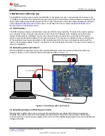
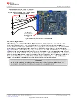

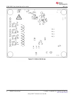

Remove cell
simulator shunts
to avoid draining
cells
If connecting cells confirm operation before connecting.
Use all appropriate fusing, insulation, isolation and
shielding necessary for safe operation. Board has exposed
contacts. Do not leave unattended
For 15 cells, connect
14th cell to both CELL14
and CELL15 inputs
...
...
Figure 4-5. Example Connection with 15 Cells
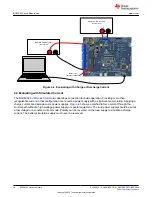
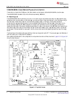
4.7 Connecting to a Host
After initial operation of the monitor with the BQStudio software, it may be desirable to operate the board
connected to and controlled by a microcontroller board. J17 could be used to connect I2C signals to the
microcontroller board with GND and REG1 for a power supply from J2. The user should note that the J2 GND is
connected to the BQ76952 VSS and BAT- while the J17 reference is PACK-. With the connection shown in
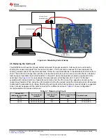
the MCU runs from the battery voltage inside the protection FETs. If the MCU board provides pull ups
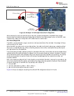
for the I2C lines, remove the PU shunts from J15 and J18. Alternately, the microcontroller board GND could be
referenced to the PACK- at J17. In this case the REG1 power supply would be modulated by the battery current.
Since the sense resistor is small, this is not normally a concern, but the user should be aware of the difference.
Do not connect the same reference to both the J2 GND and the J17 PACK- since this will short the sense
resistor through the external equipment and may lead to damage or unexpected results.
CAUTION
Do not connect the MCU board to both the J2 GND and J17 PACK- terminals, this will short the
sense resistor and could result in damage to equipment or unexpected results.
BQ76952 Circuit Module Use
SLUUC33A – NOVEMBER 2019 – REVISED OCTOBER 2020
BQ76952 Evaluation Module
21
Copyright © 2020 Texas Instruments Incorporated