background image

bq27x10EVM Circuit Module Physical Layouts

www.ti.com

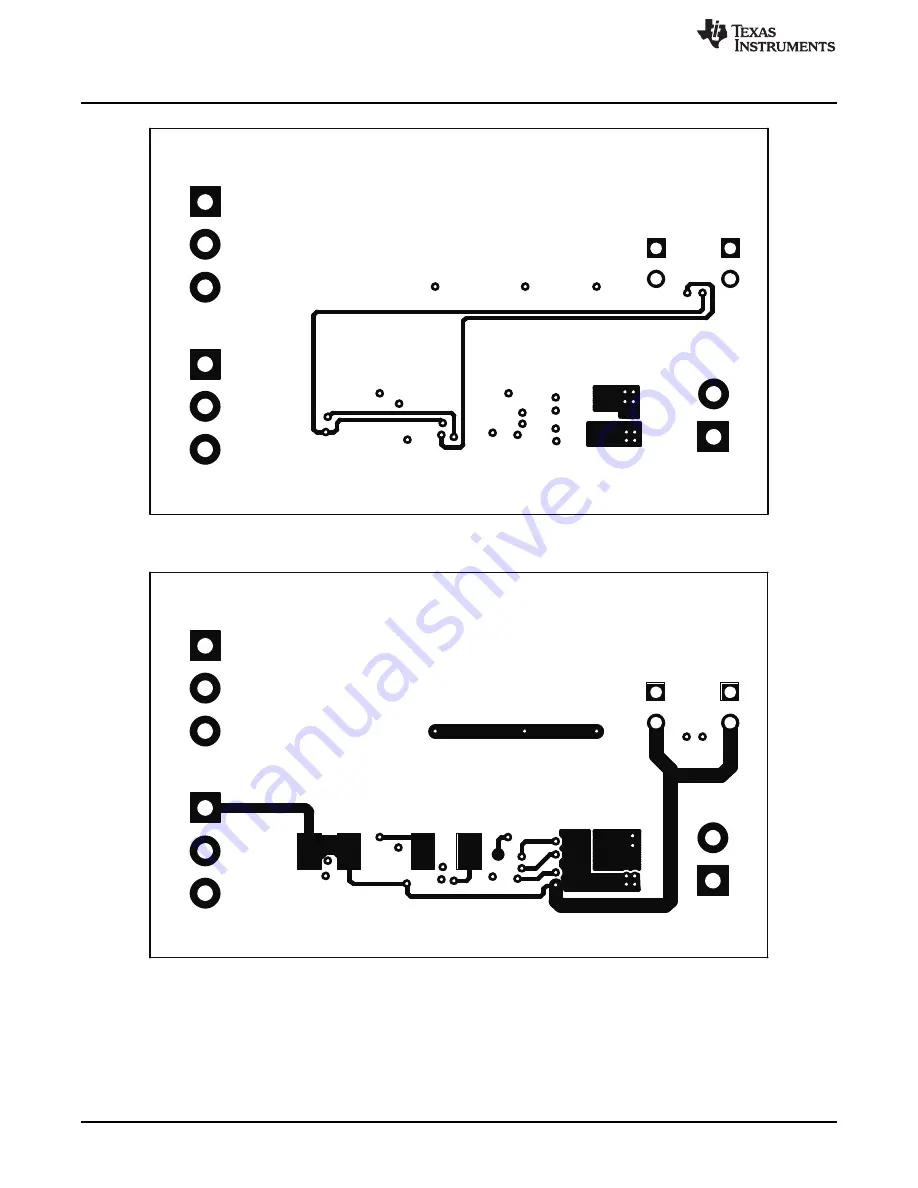
Figure 6. bq27x10EVM Layer 3 Layout

Figure 7. bq27x10EVM Layer 4 Layout

8

bq27x10EVM Single-Cell Battery Fuel Gauge Evaluation Module

SLUU259A – October 2006 – Revised October 2013

Submit Documentation Feedback

Copyright © 2006–2013, Texas Instruments Incorporated

Summary of Contents for bq27 10EVM Series

Page 1: ...Schematic 4 2 bq27x10EVM Topside Assembly 5 3 bq27x10EVM Silkscreen 5 4 bq27x10EVM Layer 1 Layout 6 5 bq27x10EVM Layer 2 Layout 7 6 bq27x10EVM Layer 3 Layout 8 7 bq27x10EVM Layer 4 Layout 8 8 bq27x10EVM Circuit Module Connection to Cells and System Load Charger 10 9 Initial Register Screen 11 10 EEPROM Screen 12 11 Pro Screen 14 12 Calibration Screen 15 List of Tables 1 Ordering Information 2 2 Te...

Page 2: ...OM and evaluate the functions of the bq27x10 under different charge and discharge conditions 1 1 Features Complete evaluation system for the bq27x10 battery gas gauge Populated circuit module for quick setup PC software and interface board for easy evaluation Software allows EEPROM programming and data logging for system analysis 1 2 Kit Contents 1 bq27x10EVM circuit module with sense resistor 2 C...

Page 3: ...ogramming the EEPROM Contacts on the circuit module provide direct connection to the cell J1 1 J2 2 and the serial communications port J1 3 The system load and charger connect across J1 1 and J2 1 Table 2 Test Points TEST POINT SIGNAL NAME DESCRIPTION J1 1 PACK Cell positive pack positive J1 2 SCL Used only with bq27210 as the I2C Clock line J1 3 SDA HDQ Single wire HDQ line for bq27010 or I2C Dat...

Page 4: ...bq27x10EVM Circuit Module Schematic Figure 1 bq27x10EVM Schematic 4 bq27x10EVM Single Cell Battery Fuel Gauge Evaluation Module SLUU259A October 2006 Revised October 2013 Submit Documentation Feedback Copyright 2006 2013 Texas Instruments Incorporated ...

Page 5: ...how the PCB layers and assembly drawing for the bq27x10EVM circuit module Figure 2 bq27x10EVM Topside Assembly Figure 3 bq27x10EVM Silkscreen 5 SLUU259A October 2006 Revised October 2013 bq27x10EVM Single Cell Battery Fuel Gauge Evaluation Module Submit Documentation Feedback Copyright 2006 2013 Texas Instruments Incorporated ...

Page 6: ...ayouts www ti com Figure 4 bq27x10EVM Layer 1 Layout 6 bq27x10EVM Single Cell Battery Fuel Gauge Evaluation Module SLUU259A October 2006 Revised October 2013 Submit Documentation Feedback Copyright 2006 2013 Texas Instruments Incorporated ...

Page 7: ... Physical Layouts Figure 5 bq27x10EVM Layer 2 Layout 7 SLUU259A October 2006 Revised October 2013 bq27x10EVM Single Cell Battery Fuel Gauge Evaluation Module Submit Documentation Feedback Copyright 2006 2013 Texas Instruments Incorporated ...

Page 8: ...Figure 6 bq27x10EVM Layer 3 Layout Figure 7 bq27x10EVM Layer 4 Layout 8 bq27x10EVM Single Cell Battery Fuel Gauge Evaluation Module SLUU259A October 2006 Revised October 2013 Submit Documentation Feedback Copyright 2006 2013 Texas Instruments Incorporated ...

Page 9: ... 2 Resistor chip 15 kΩ 1 16 W 5 603 Std Std R15 1 1 Resisitor chip 10kΩ 1 16 W 5 402 Std Std R8 1 1 Resistor chip 0 02 Ω 0 25 W 1 1206 Vishay WSL1206 U1 1 0 Single cell Li Ion Polymer gas gauge device QFN Texas bq27010DRK Instruments U1 0 1 Single cell Li Ion Polymer gas gauge device QFN Texas bq27210DRK Instruments J1 J3 2 2 Terminal blocks 3 position OST ED1515 J2 1 1 Terminal blocks 2 position ...

Page 10: ...onnecting the bq27x10EVM Circuit Module to a Battery Pack Figure 8 shows how to connect the bq27x10EVM circuit module to a Li ion cell and the system load charger Figure 8 bq27x10EVM Circuit Module Connection to Cells and System Load Charger 7 2 2 PC Interface Connection The following steps configure the hardware for interface to the PC 1 Connect colored wires that are included with EV2300 to bq27...

Page 11: ... ground 8 Operation 8 1 Starting the Program Run the program from the Start Programs Texas Instruments bq27X10 Battery Gas Gauge menu sequence The software defaults to the PC USB port for communication If the EV2300 is connected to USB port the program should load and display the initial data screen If it is the first time that the program is used then the user is prompted to select between the bq...

Page 12: ...to engineering units A check mark in the display engineering units box displays the data set in engineering units No check mark displays the data set just as the bq27x10 calculates them i e in units of 3 57 μVh counts 8 2 2 Programming the bq27x10 EEPROM Each bq27x10 is programmed at the factory with default values in the EEPROM The values in EEPROM should be changed to match specific applications...

Page 13: ...f communication interface EV2300 or EV2200 8 3 2 Commands Menu With the bq27x10 several commands are performed by setting the appropriate bit in the MODE register and then writing 0xA9 or 0x56 into address 0x00 With the Commands menu of the EVSW the user may perform the commands automatically Among the selections are WRTNAC If a user wants to write the NAC register to a specific value the user wri...

Page 14: ...nted in hexadecimal numbers If either the DCFIX or TCFIX bits in the Pack Configuration EEPROM register are set then the DCOMP or TCOMPis illustrated as Customer ID accordingly For example if DCFIX bit is set then the DCOMP register is set as a customer ID and the default discharge rate compensation is used by the bq27x10 regardless of the contents of the DCOMP register The EEPROM screen has two g...

Page 15: ...x10 registers can be logged by using the data log function To log the data and create a log file 1 Select the registers to log by clicking on the corresponding Log box in each row of data 2 Select File Start Data Log from the pulldown menu 3 Enter the name of the data log file in the Name Datalog File box 4 Click on the Open button 5 To stop the data logging select File Close Data Log from the pul...

Page 16: ...3 34 12 3 33 20 PM 120 3754 1075 74 1033 34 13 3 33 30 PM 130 3762 1075 74 1033 34 14 3 33 40 PM 140 3765 1075 74 1033 34 15 3 33 50 PM 150 3767 1075 74 1033 34 16 3 34 00 PM 160 3622 1073 91 1032 73 17 3 34 10 PM 170 3609 1072 69 1032 73 18 3 34 20 PM 180 3598 1070 25 1032 73 19 3 34 30 PM 190 3593 1065 52 1032 73 20 3 34 40 PM 200 3695 1065 52 1032 73 21 3 34 50 PM 210 3810 1065 52 1032 73 22 3 ...

Page 17: ...ency energy and has not been tested for compliance with the limits of computing devices pursuant to part 15 of FCC or ICES 003 rules which are designed to provide reasonable protection against radio frequency interference Operation of the equipment may cause interference with radio communications in which case the user at his own expense will be required to take whatever measures may be required t...

Page 18: ... its gain should be so chosen that the equivalent isotropically radiated power e i r p is not more than that necessary for successful communication This radio transmitter has been approved by Industry Canada to operate with the antenna types listed in the user guide with the maximum permissible gain and required antenna impedance for each antenna type indicated Antenna types not included in this l...

Page 19: ...tained the Technical Regulations Conformity Certification as provided in Radio Law of Japan with respect to this product Also please do not transfer this product unless you give the same notice above to the transferee Please note that if you could not follow the instructions above you will be subject to penalties of Radio Law of Japan Texas Instruments Japan Limited address 24 1 Nishi Shinjuku 6 c...

Page 20: ...derations per the user guidelines Exceeding the specified EVM ratings including but not limited to input and output voltage current power and environmental ranges may cause property damage personal injury or death If there are questions concerning these ratings please contact a TI field representative prior to connecting interface electronics including input power and intended loads Any loads appl...

Page 21: ...esponsible for compliance with all legal regulatory and safety related requirements concerning its products and any use of TI components in its applications notwithstanding any applications related information or support that may be provided by TI Buyer represents and agrees that it has all the necessary expertise to create and implement safeguards which anticipate dangerous consequences of failur...

Reviews: