


Testing the EVM Data Capture with LVDS Interface
10
SLOU489 – August 2017
Copyright © 2017, Texas Instruments Incorporated
AFE5832 32-Channel Analog Front-End Evaluation Module (EVM Rev. A)
4.2
Capturing an Analog Input Signal With the LVDS Interface
This section describes the software setup for capturing an analog input using the AFE5832 EVM. If there
is any issue with a data capture, refer to the troubleshooting section.
Data capture is confirmed by using only the
Quick Setup
page of the AFE5832 GUI. Assuming the
hardware is connected correctly as in
, follow these steps to acquire data:
4.2.1
HSDC Pro Actions
1. Connect both EVMs to the PC using two USB cables as instructed in
.
2. Open the HSDC Pro GUI using
Run as Administrator
.
Do not open the AFE5832 GUI before this
step because it opens automatically. If it is already open, close it.
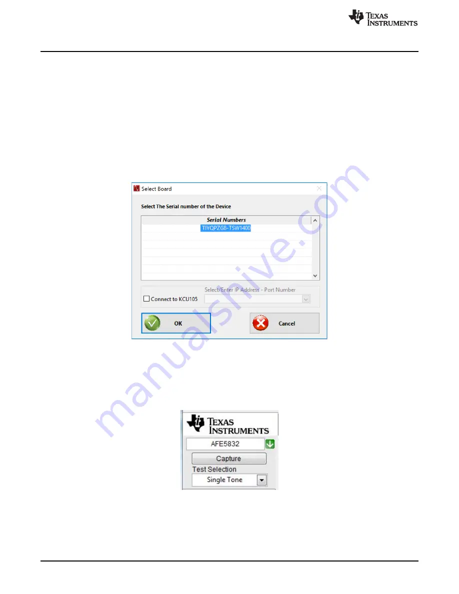
3. If the TSW Hardware is already connected to the USB, then a pop-up window should appear to
connect the HSDC Pro GUI to the EVM Hardware.
Figure 5. Connect to TSW EVM (TSW1400 Shown)
4. A pop-up window prompts the user to choose a firmware to download to the TSW EVM FPGA.
5. Select firmware: In the upper left-hand corner "Select ADC" box, type the name of your device and the
drop-down list will automatically filter based on your input. Then, from the drop-down, choose your
desired format.
Be sure to choose the correct device to match the AFE5832 EVM hardware or the
AFE5832 GUI will show an error when launching.
Figure 6. Choose Firmware
6. When prompted to update the firmware, click the
Yes
button.
7. The firmware begins downloading to the FPGA on the TSW EVM.
8. When the firmware has finished downloading, several Green LEDs are lit on the TSW EVM. For the
TSW1400, D5 (USER_LED3) is usually off when the EVM is not configured, and D6 is off.