3 AFE4500 EVM Hardware
CAUTION
Many of the components on the AFE4500EVM are susceptible to damage by electrostatic discharge
(ESD). Customers are advised to observe proper ESD handling precautions when unpacking and
handling the EVM, including the use of a grounded wrist strap, bootstraps, or mats at an approved
ESD workstation. Safety glasses should also be worn
The bill of materials (BOM) is provided in
. The PCB layouts are shown in
MSP430F5528 is the microcontroller used on the board. For more details of the MSP430F5528, visit
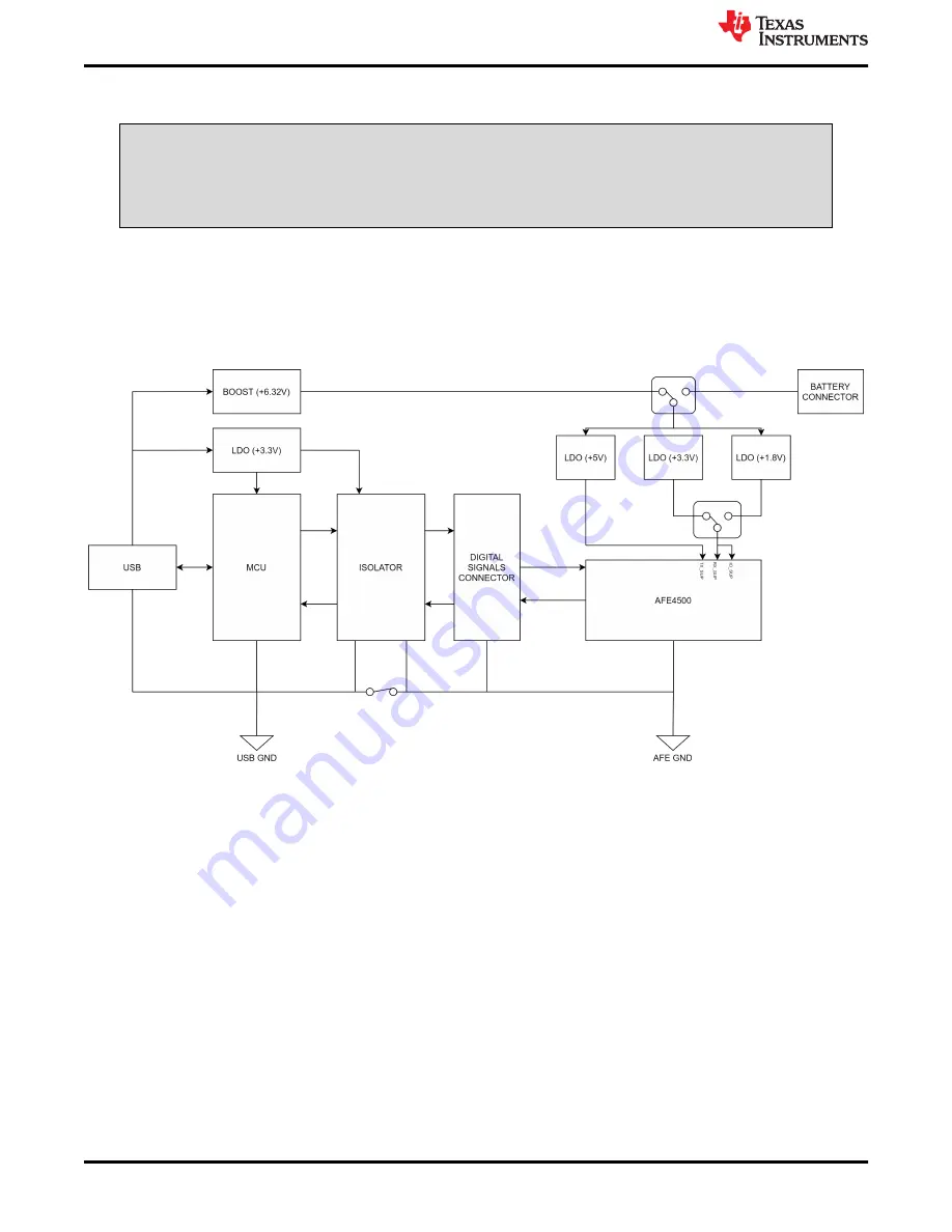
The following sections explain the main hardware components available on the EVM. Figure 15 shows the
functional block diagram for the EVM.
Figure 3-1. AFE4500EVM Block Diagram
3.1 Power Supply
By default, the EVM is configured to LDO enable mode with RX_SUP = IO_SUP = 3.3 V and TX_SUP = 5V.
There is an option to configure the EVM in LDO Bypass mode where RX_SUP = IO_SUP = 1.8 V and TX_SUP
= 5 V.
By default, the power for the board is derived from the USB. The USB data bus is ESD protected using TI’s
ESD protection diode array TPD2E001DRLR. The supply for controller is derived from USB supply using a 3.3V
LDO
TPS7A0233PDQNR
. AFE4500 RX and IO supply is generated from two LDOs,
LP38693SD-1.8/NOPB
and
LP38693SD-3.3/NOPB.
TX supply is generated from USB supply. USB supply is firstly boosted using
TPS61252DSGR
and then using a LDO
LP38693SD-5.0
regulated 5 V is generated.
LDO Enable Mode
: Place shunts at J7[1-2]
LDO Bypass Mode
: Place shunts at J7[3-2]
Series jumper J9 is provided to measure the supply voltages and confirm they are proper. Short J9 if not used for
measuring RX current.
AFE4500 EVM Hardware
16
AFE4500 EVM User Guide
SBAU370 – APRIL 2021
Copyright © 2021 Texas Instruments Incorporated


