2.2 Evaluation Board Feature Identification Summary
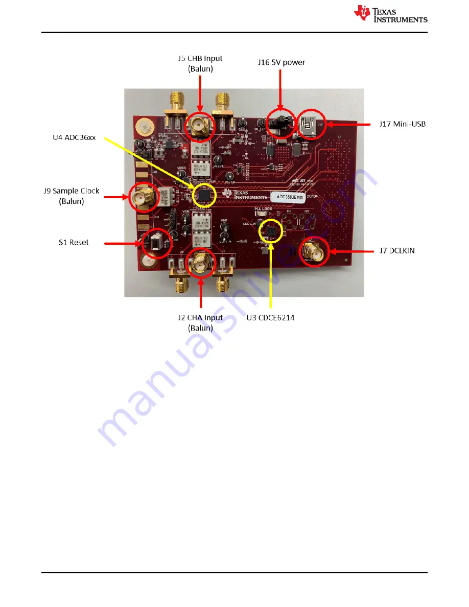
Figure 2-3. ADC366xEVM Feature Identification
Ensure that jumper J16 is shunted in the 2-3 position. This allows 5 V to be supplied to the ADC366xEVM
through the mini-USB connector.
If an external 5-V supply is desired, J16 must be shunted in the 1-2 position, and the external 5 V can be
connected to the test point labeled "+5 EXT". The USB data connection is still connected for SPI
communications.
J13 is tied to the REFBUF pin. It can be left floating, or can be tied to 1.8 V (shunt pins 2-3) for normal operation.
J14 is tied to the PDN/SYNC pin. It can be left floating for tied to ground (shunt pins 1-2) for normal operation. To
power down the ADC, tied to 1.8 V (shunt pins 2-3). The ADC may also be powered down via SPI.
Equipment
4
ADC366xEVM Evaluation Module
SBAU366 – JANUARY 2021
Copyright © 2021 Texas Instruments Incorporated


