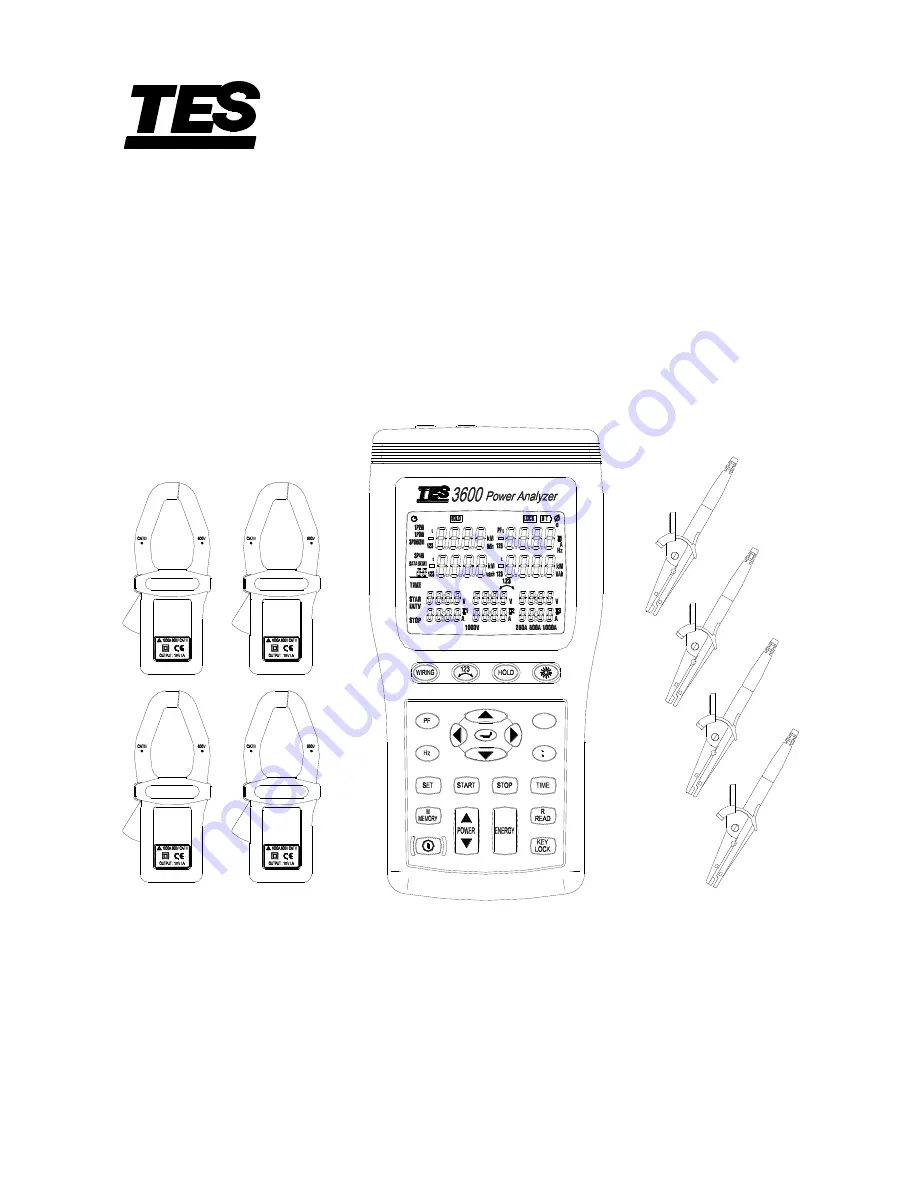
3P4W POWER ANALYZER
TES - 3600
INSTRUCTION MANUAL
3
4
1
2
I4
U3 m-s
U12 Y-M
U23 D-h
£c
NO.
Q
P
S
TES ELECTRICAL ELECTRONIC CORP.
Shop for Data Logging products online at:
www.
DataLoggerStore
.ca
1.877.766.5412
Page 1: ...P4W POWER ANALYZER TES 3600 INSTRUCTION MANUAL 3 4 1 2 I4 U3 m s U12 Y M U23 D h c NO Q P S TES ELECTRICAL ELECTRONIC CORP Shop for Data Logging products online at www DataLoggerStore ca 1 877 766 541...
Page 2: ...Wire 1P3W Power System Measurement 20 5 4 Three Phase 3 Wire 3P3W Power System Measurement 23 5 5 Three Phase 4 Wire 3P4W Power System Measurement 26 5 6 Only One Current I4 Measurement 29 5 7 Manual...
Page 3: ...t with the conductor could result in electric shock To avoid damages to the meter do not exceed the maximum limits of the input values shown in the specifications Use the meter only as specified in th...
Page 4: ...40 Do not store or use the meter where it will be exposed to direct sunlight high temperature high humidity or condensation if exposed to such conditions the meter may be damaged the insulation may de...
Page 5: ...jaws of alligator clips can create a short circuit between closely spaced live parts Avoid making connections to feeder conductors or bus bars at elevated potentials Whenever please make connections t...
Page 6: ...of showing many power quality parameters at the same time 4 current probe including for measuring a neutral line current Measures single phase 2 wire single phase 3 wire three phase 3 wire and three p...
Page 7: ...vided by the probe assembly may be impaired 3 3 General Specification Maximum voltage between voltage input terminals and earth ground 1000 Vrms Maximum rated working voltage for current input 0 35 Vr...
Page 8: ...o Ltd Category Rating CAT III 1000V AC 10A Max 3 Alligator clip x 4pcs Model no FC A23 Manufacturer Fu Chyi Enterprise CO Ltd Category Rating CAT III 1000V AC 10A Max 4 AC Adaptor IN OUT Isolated type...
Page 9: ...item RMS current value for each channel Active Power measurement P KW Range Resolution Accuracy 999 9KW 0 1KW 1 0 rdg 20dgts Display items Active power of each channel and its sum of multiple channels...
Page 10: ...current is slower than voltage No symbol For phase lead LEAD current is faster than voltage Frequency measurement Hz Range Resolution Accuracy Measurement source 60HZ 0 1Hz 0 1 rdg 2dgt Voltage U1 50...
Page 11: ...val Timer Accuracy 3 999Kvarh 0 001Kvarh 1 0 rdg 20dgt 1 sec 50ppm 25 77 39 99Kvarh 0 01Kvarh 399 9Kvarh 0 1Kvarh 3 999Mvarh 0 001Mvarh 39 99Mvarh 0 01Mvarh 119 3Mvarh 0 1Mvarh Measurement display Dis...
Page 12: ...10 IV PARTS CONTROLS 4 1 Description of Parts Control keys U12 Y M Q NO P c I4 U3 m s S U23 D h I3 I1 I4 I2 N U1 U2 U3 Shop for Data Logging products online at www DataLoggerStore ca 1 877 766 5412...
Page 13: ...hold function key press HOLD key to hold data the HOLD annunciator is displayed press HOLD key again to exit Hold function Press and hold down HOLD key then press key turn on the meter the mark disap...
Page 14: ...number is displayed total memory size is 99 sets 20 READ key Read manual memory data control key 21 POWER Key Display measured power value control key the Pt123 Qt123 and St123 annunciators will be d...
Page 15: ...PF3 Phase 3 power factor measured display PFt Total power factor measured display I4 Current probe 4 current measured display Hz Frequency unit DATA No Last manual datalogged memory address number ind...
Page 16: ...data and time indication Y M D h m s Date and time displayed INTV Auto datalogging interval time setting indication START Energy calculating start time indication STOP Energy calculating stop time in...
Page 17: ...uring the measurement of U2 U3 I1 I2 and I3 because U1 is the main signal source of the whole meter measuring system Otherwise you could not have any measurement from U2 U3 I1 I2 and I3 5 1 AC Current...
Page 18: ...or weakened components Pay particular attention to the insulation surrounding the clamp jaws Do not use a damaged Current Clamp If a clamp is damaged tape it shut to prevent unintended operation Meas...
Page 19: ...shooting electrical distribution system Measuring current harmonic use PC Measuring line rms voltage Measuring power on single phase loads Measuring line rms current Measuring frequency Measuring volt...
Page 20: ...rrent connect the I4 current probe output plug to the I4 jack 4 Connect the voltage test leads and current probe to the electrical equipment to be tested CAUTION If possible before connecting the volt...
Page 21: ...Press ENERGY key the Pt Qt St and PFt or t annunciator and energy integrate start time are displayed The energy integrate value and the current time will be continuous accumulate a KW displays KWh b K...
Page 22: ...tem measurement A B Line N Neutral G Ground Face the arrow toward the load I3 I4 I1 I2 N U2 U1 U3 1P3W Wiring Connection Diagram 1 Press key to turn on the meter 2 Press WIRING key to select the 1P3W...
Page 23: ...ed voltage test alligator to the line A Connect the yellow voltage test alligator to the line B Press I1 current probe trigger to open the jaw and fully enclose the Line A 11 Press I2 current probe tr...
Page 24: ...and the current time will be continuous accumulate a KW displays KWh b KVAR displays KVARh c KVA displays KVAh Press STOP key to stop energy accumulated and the HOLD annunciator is displayed Press ke...
Page 25: ...3 phase balanced and unbalanced system Measuring power factor of 3 phase motors Measuring voltage harmonics use PC Unbalance factor When the load of the specified phase becomes too heavy due to fluctu...
Page 26: ...before connecting the voltage test leads and current probe to the electrical equipment to be tested take off the electrical equipment s power Connect the black voltage test alligator to the line B Con...
Page 27: ...and the current time will be continuous accumulate a KW displays KWh b KVAR displays KVARh c KVA displays KVAh Press STOP key to stop energy accumulated and the HOLD annunciator is displayed Press ke...
Page 28: ...e voltage test leads and current probe to the meter Connect the black voltage test lead to the N terminal Connect the red voltage test lead to the U1 terminal Connect the yellow voltage test lead to t...
Page 29: ...er to open the jaw and fully enclose the Line A 14 Press I2 current probe trigger to open the jaw and fully enclose the Line B 15 Press I3 current probe trigger to open the jaw and fully enclose the L...
Page 30: ...and the current time will be continuous accumulate a KW displays KWh b KVAR displays KVARh c KVA displays KVAh Press STOP key to stop energy accumulated and the HOLD annunciator is displayed Press ke...
Page 31: ...gger to open the jaw and fully enclose desired measured wire 5 Read the I4 value if the measured current value greater than 250A the display will show the OL symbol 5 7 Manual Data Memory and Read Fun...
Page 32: ...t YEAR month DAY hour minute second Press key to enter auto datalogging interval time setting the INTV annunciator is displayed Press keys cycle select the interval time you can select 5 seconds 30 se...
Page 33: ...e must be greater than 30V then press and hold down key If connection wires is normal phase the annunciator is displayed If connection wires is reverse phase the annunciator is displayed Release the k...
Page 34: ...r alcohol These may damage the text 3 Additional to this it is recommended to open the jaws of the Current Clamp and to wipe the magnetic pole pieces with a lightly oiled cloth This in order to avoid...
Page 35: ...ON For the detailed instruction please refer to the content of attached CD disk which has the complete instruction of RS 232 interface software operation and relevant information Shop for Data Logging...
Page 36: ...No 31 Lane 513 Rui Guang Road Neihu Dist Taipei Taiwan R O C Tel 02 2799 3660 Fax 886 2 2799 5099 E Mail tes ms9 hinet net http www tes com tw Jan 2008 9 Shop for Data Logging products online at www...