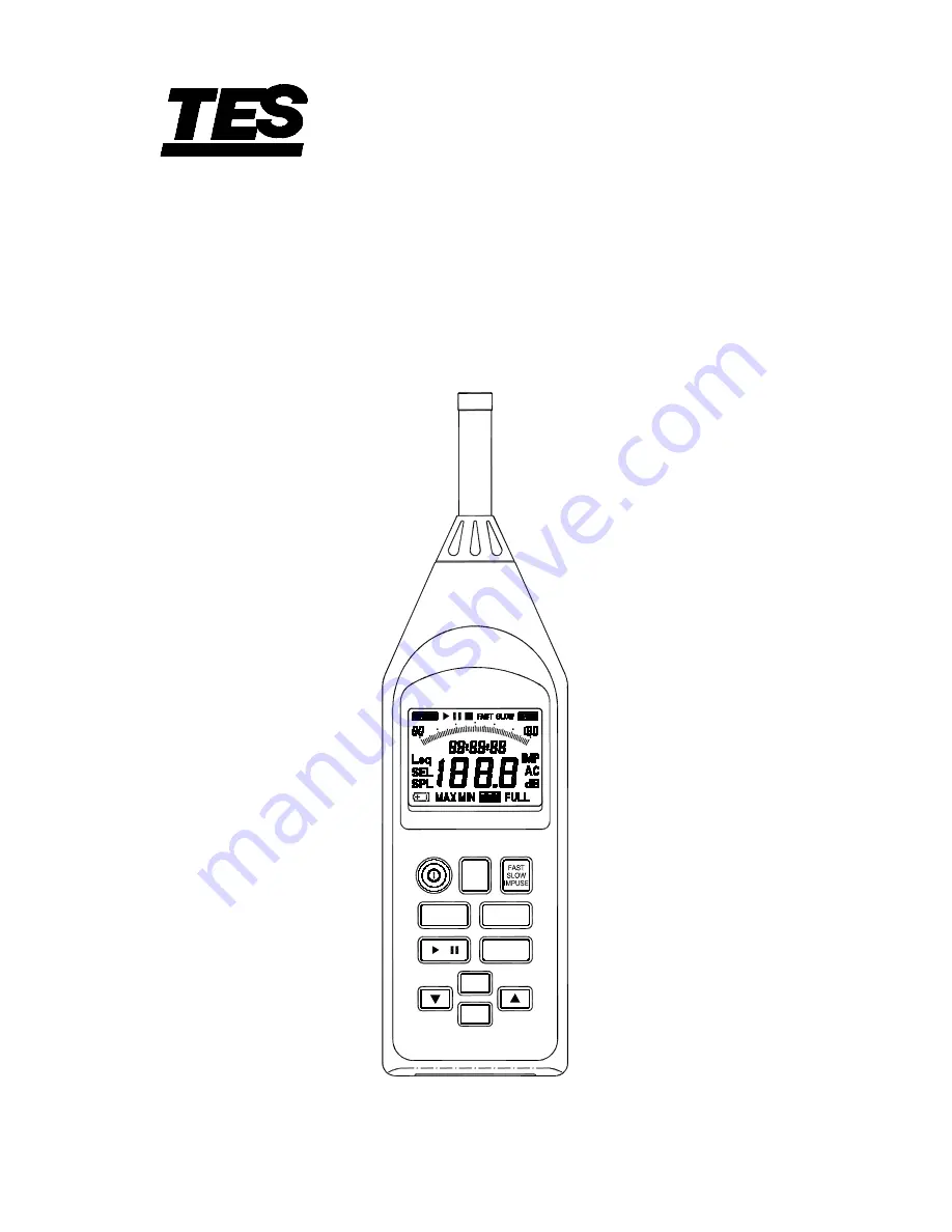
INTEGRATING
Sound Level Meter
TES-1353S
INSTRUCTION MANUAL
※
Enclosed CD : Software & Protocol Inside.
INTEG
DATE
TIME
A/C
ERASE
Leq SEL SPL
RECORD
MAX
TES ELECTRICAL ELECTRONIC CORP.
Page 1: ...INTEGRATING Sound Level Meter TES 1353S INSTRUCTION MANUAL Enclosed CD Software Protocol Inside INTEG DATE TIME TIME A C ERASE Leq SEL SPL RECORD MAX TES ELECTRICAL ELECTRONIC CORP...
Page 2: ...ONS 8 6 LCD DISPLAY DESCRIPTION 10 7 PREPARATION FOR USE 12 8 CALIBRATION PROCEDURE 14 9 MEASUREMENT PROCEDURE 15 10 SETTING THE CURRENT TIME AND DATE 17 11 STORE RECORD DATA OPERATION 18 12 OUTPUT CO...
Page 3: ...ecessary with a cloth lightly moistened with water Do not use any solvents alcohol or cleaning agents 2 FEATURES The Sound Level Meter complies with the requirements of IEC 61672 1 2003 standard for a...
Page 4: ...ound level L 90 90 percentile sound level L 95 95 percentile sound level SPL MAX Maximum time weighted sound pressure level MAX symbol blink The various settings depend on the condition the instrument...
Page 5: ...e nominal microphone equivalent capacitance of 27pF 30 90dB range Weighting Electrical Total A 22 7dB 26 1dB C 21 8dB 29 5dB Linearity operating range A weighted 1000Hz 60dB dynamic range Total linear...
Page 6: ...dB Test starting point 94 dB for all weightings and frequencies except 31 5Hz A weighted for which the starting point is 74 dB FREQUENCY Hz WEIGHTING L O R dB WEIGHTING L O R dB 31 5 A 60 0 80 6 C 60...
Page 7: ...Warm up time 2min Sampling interval Bar graph indication 125 ms approx Numeric indication 1 sec approx Data record capacity Data can be stored in the memory Max 200M data can be stored micro SD CARD...
Page 8: ...0 RH non condensing Storage conditions 10 to 60 70 RH non condensing Effect of temperature 0 5dB 10 to 50 Effect of humidity 0 5dB for 30 RH to 90 RH at 40 1000Hz Effect of vibration A 40 Hz 1m s vibr...
Page 9: ...the above standard No degradation in performance when the instrument was subjected to ESD at 8kV per IEC 801 2 Dimensions Approx 265 L 72 W 36 H mm Weight including battery Approx 380g Supplied access...
Page 10: ...d warning indications 3 Button Press to turn the instrument on and off 4 Leq SEL SPL button Press this button the following parameters are monitored during integrating measurement and can be viewed se...
Page 11: ...E mode FAST uses a 125ms time constant This setting is used in most situations SLOW uses a 1s time constant which smooth out fluctuating levels IMPULSE uses a 35ms time constant with a slow decay whic...
Page 12: ...ange from 1 second to 100 hours 13 micro SD CARD 4GB 14 CAL potentiometer Calibration potentiometer for level adjustment 15 Micro USB USB input output connector for input of control signals and output...
Page 13: ...und level reading 9 MIN Minimum sound level reading 10 REC Data records indicator 11 Sound level reading 0 1dB resolution 30 0 130 0dB 12 FULL Data records full indicator 13 dB Sound level unit 14 A C...
Page 14: ...given in section 4 Specifications Refit the battery cover and screw Use a screwdriver to tighten the screw Press the button to turn on the instrument and check for correct operation Note Take care no...
Page 15: ...equipment or similar wind noise and strong air movements at the microphone can cause measurement errors Such effect can be reduced by using the windscreen 4 Tripod Mounting For long term measurements...
Page 16: ...e the SLOW IMPUSE FAST button to select FAST time weighting 6 Insert the microphone very carefully and slowly all the way into the sound calibrator coupling orifice 7 Switch on the 1000Hz sound calibr...
Page 17: ...tching and will clear when the correct range is selected 6 The numeric level indication shows the currently measured sound level The reading is updated once every second Press DATE TIME button changed...
Page 18: ...e minute repeat this procedure until you have set to desired minute and hour Press INTEG TIME button to stored the desired measurement time to the new manual setting time and exit this mode The maximu...
Page 19: ...ld L05 L10 L50 L90 L95 and SPL sound level up to that point This applies only to the numeric level display the bar graph indication shows the current sound level The percentile sound level only calcul...
Page 20: ...ond Press and buttons to set desired second Press INTEG TIME button move to the next parameter the minute repeat this procedure until you have set to desired minute and hour Press INTEG TIME button to...
Page 21: ...sound level with start measurement time SEL Sound exposure level with terminate measurement time SPL MAX Maximum sound level with time SPL MIN Minimum sound level with time PH Peak Hold sound level L...
Page 22: ...ally the start symbol the REC flashing symbol and the elapsed measurement time is displayed enter to record data mode and integrating sound measurement mode 7 During measurement press button can be us...
Page 23: ...ph indication shows the current sound level The percentile sound level only calculated to 100 hours 9 If the measurement terminates automatically the recorded blocks number 1 to 255 display one time a...
Page 24: ...ld down button then press button turn on the meter enter to printing data mode 13 OUTPUT CONNECTORS 13 1 AC Output An AC signal corresponding to the frequency weighted signal is available at this conn...
Page 25: ...tored the setting and exit this mode 5 If the measured dB level exceeds the set limit the over limit signal will appear at the alarm output connector 5Vdc output The output signal will remain active a...
Page 26: ...TES ELECTRICAL ELECTRONIC CORP 7F No 31 Lane 513 Rui Guang Road Neihu Dist Taipei Taiwan R O C Tel 02 2799 3660 Fax 886 2 2799 5099 E Mail tes ms9 hinet net http www tes com tw Mar 2013...