


DS_1209F_004
73S1209F Data Sheet
Rev. 1.2
61
1.7.11 Keypad Interface
Keypad Interface
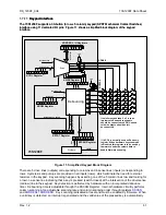
The 73S1209F supports a 30-button (6 row x 5 column) keypad (SPST Mechanical Contact Switches)
interface using 11 dedicated I/O pins. Figure 11 shows a simplified block diagram of the keypad
interface.
The 73S1209F supports a 30-button (6 row x 5 column) keypad (SPST Mechanical Contact Switches)
interface using 11 dedicated I/O pins. Figure 11 shows a simplified block diagram of the keypad
interface.
Scan
pu
ll-
up
Debouncing
De
bo
un
ce
T
im
e
7
6
5
4
3
2
1
0
KSIZE Register
6
(1) KCOL is normally used as Read only
register. When hardware keyscan mode
is disabled, this register is to be used by
firmware to write the column data to
handle firmware scanning.
Key
_
D
e
te
ct
Hardware Scan Enable
6
Co
lu
m
n
Sc
an
O
rd
er
5
Column Value
Row Value
K
ey_D
et
ec
t_
E
nab
le
KORDERL / H Registers
7
6
5
4
3
2
1
0
7
6
5
4
3
2
1
0
7
6
5
4
3
2
1
0
KCOL Register
(1)
7
6
5
4
3
2
1
0
KROW Register
Dividers
1kHz
Sc
an
Ti
me
KSCAN Register
7
6
5
4
3
2
1
0
7
6
5
4
3
2
1
0
KSTAT Register
Keypad Clock
Keypad Clock
VDD
pu
ll-
up
COL4:0
RO
W5
:0
73S1209F
If smaller keypad than 6 x 5 is to be
implemented, unused row inputs
should be connected to VDD. Unused
column outputs should be left
unconnected.
VDD
Figure 11: Simplified Keypad Block Diagram
There are 5 drive lines (outputs) corresponding to columns and 6 sense lines (inputs) corresponding to
rows. Hysteresis and pull-ups are provided on all inputs (rows), which eliminate the need for external
resistors in the keypad. Key scanning happens by asserting one of the 5 column lines low and looking for
a low on a sense line indicating that a key is pressed (switch closed) at the intersection of the drive/sense
(col/row) line in the keypad. Key detection is performed by hardware with an incorporated debounce
timer. Debouncing time is adjustable through the KSCAN Register. Internal hardware circuitry performs
column scanning at an adjustable scanning rate and column scanning order through registers
. Key scanning is disabled at reset and must be enabled by firmware. When
a valid key is detected, an interrupt is generated and the valid value of the pressed key is automatically


