


DS_1209F_004
73S1209F Data Sheet
Rev. 1.2
53
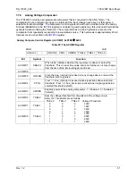
1.7.9 LED Drivers
The 73S1209F provides two dedicated output pins for driving LEDs. The LED driver pins can be
configured as current sources that will pull to ground to drive LEDs that are connected to VDD without the
need for external current limiting resistors. These pins may be used as general purpose outputs with the
programmed pull-down current and a strong (CMOS) pull-up, if enabled. The analog block must be
enabled when these outputs are being used to drive the selected output current.
The pins may be used as inputs with consideration of the programmed output current and level. The
register bit when read, indicates the state of the pin.
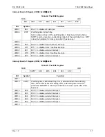
LED Control Register (LEDCtl): 0xFFF3
Å
0xFF
Table 57: The LEDCtl Register
MSB LSB
– LPUEN
ISET.1
ISET.0 –
– LEDD
1 LEDD0
Bit Symbol
Function
LEDCtl.7 –
LEDCtl.6
LPUEN
0 = Pull-ups are enabled for all of the LED pins.
LEDCtl.5 ISET.1
These two bits control the drive current (to ground) for all of the LED driver
pins. Current levels are:
00 = 0ma(off)
01 = 2ma
10 = 4ma
11 = 10ma
LEDCtl.4 ISET.0
LEDCtl.3 –
LEDCtl.2 –
LEDCtl.1
LEDD1 Write data controls output level of pin LED1. Read will report level of pin LED1.
LEDCtl.0
LEDD0
Write data controls output level of pin LED0. Read will report level of pin LED0.