


Service and Repair Manual
December 2019
Platform Components
32
S
®
-60 J
Part No. 1285305GT
How to Per form a Z ero Load Platform Overload C alibration
How to Perform a Zero Load
Platform Calibration
Perform this procedure when the required weight
for full load calibration is not available. This
procedure will re-calibrate the zero load point
without affecting a previous full load calibration.
The platform load capacity will be reduced until a
full load calibration has been performed. A full load
calibration is required for rated load performance.
Note: Perform this procedure with the machine on
a firm, level surface.
Note: The turntable level sensor must be calibrated
before performing this procedure.
1 Fully retract the boom. Level the platform.
2 Remove all material, tools and equipment
from the platform. Remove the welder, if
equipped.
Tip-over hazard. Failure to
remove all factory and
non-factory accessories could
result in the machine tipping
over, causing death or serious
injury.
3 Enter Service Mode. Refer to Repair
Procedure,
How to Enter the Service Mode
.
4 Press the settings button above the display
and navigate to the Sensor Calibrations menu.
5 Navigate to the Load Sense calibration
screen.
6 Select and start the calibration procedure.
7 Follow the on-screen instructions to set the
zero load.
8 Continue to follow the prompts to accept the
weight.
9 The calibration is now complete.
Exit the Service Mode
How to R eplace the Platform Overload Load C ell
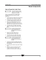
How to Replace the Load Cell
Sensor
Note: The preload adjustment should only be
performed after the load cell sensor has been
replaced.
1 Remove all equipment or tools from the
platform. Remove the welder if equipped.
2 At the platform, remove the plastic instruction
holder from the document mount plate.
3 Tag and disconnect the load cell sensor
harness.
1 flex plate
2 load cell sensor foot
3 jam nut
4 load cell sensor
4 Loosen the jam nut securing the load cell
sensor foot and rotate the foot screw
clockwise to remove the preload.
5 Remove the fasteners securing the load cell
sensor and remove the sensor.
Summary of Contents for S-60 J
Page 67: ...December 2019 Service and Repair Manual Manifolds Part No 1285305GT S 60 J 55 ...
Page 69: ...December 2019 Service and Repair Manual Manifolds Part No 1285305GT S 60 J 57 ...
Page 77: ...December 2019 Service and Repair Manual Manifolds Part No 1285305GT S 60 J 65 ...
Page 115: ...December 2019 Service and Repair Manual 103 Electrical Schematic Generator Options ...
Page 118: ...Service and Repair Manual December 2019 106 Electrical Schematic Positive Air Shutdown ...
Page 119: ...December 2019 Service and Repair Manual 107 Electrical Schematic Turntable Controller ...
Page 122: ...Service and Repair Manual December 2019 110 Electrical Schematic Platform Controller ...
Page 123: ...December 2019 Service and Repair Manual 111 Electrical Schematic Kubota D1803 ...
Page 126: ...Service and Repair Manual December 2019 114 Electrical Schematic Kubota D1105 ...
Page 127: ...December 2019 Service and Repair Manual 115 Electrical Schematic Deutz D2011 ...
Page 129: ...December 2019 Service and Repair Manual Part No 1285305GT S 60 J 117 Hydraulic Schematic ...
Page 131: ......