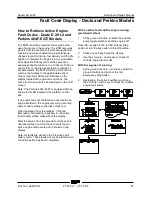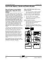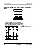
November 2020
Service and Repair Manual
Control System Fault Codes
Part No. 1268197GT
Z
®
-45 XC
™
• Z
®
-45 HF
81
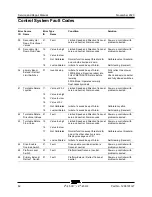
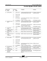
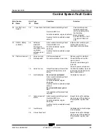
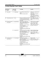
Control Syst em F ault C odes
Error Source
Error Type
Condition
Solution
ID
Name
ID
Name
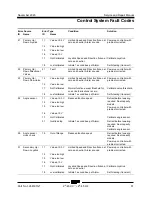
21
Primary Up /
Down Joystick
11
Value at 5.0 V
Limited Speed and Direction frozen at
zero and neutral, Alarm sounds.
Power up controller with
problem corrected.
12
Value too high
15
Value too low
16
Value at 0 V
17
Not Calibrated
Joystick Speed and Direction frozen at
zero and neutral.
Calibrate Joystick.
18
Just calibrated
Initiate 1 second beep of Alarm.
Self-clearing (transient)
22
Primary Up /
Down Directional
Valves
21
Fault
Limited Speed and Direction frozen at
zero and neutral, Alarm sounds.
Power up controller with
problem corrected.
23
Primary Up /
Down Flow Valve
12
Value too high
Limited Speed and Direction frozen at
zero and neutral, Alarm sounds.
Power up controller with
problem corrected.
15
Value too low
17
Not Calibrated
Normal function except threshold for
one or both directions is zero.
Calibrate valve threshold.
18
Just calibrated
Initiate 1 second beep of Alarm.
Self-clearing (transient)
24
Angle sensor
11
Value at 5.0 V
Reduced function speed
Retract before lowering
required. Dual capacity
models.
Power up controller with
problem corrected.
12
Value too high
15
Value too low
16
Value at 0 V
17
Not Calibrated
Calibrate angle sensor.
31
Invalid setup
Initiate 1 second beep of Alarm.
Retract before lowering
required. Dual capacity
models.
Calibrate angle sensor.
26
Angle sensor
cross check
19
Out of Range
Reduced function speed
Retract before lowering
required. Dual capacity
models.
Power up controller with
problem corrected.
31
Secondary Up /
Down. Joystick
11
Value at 5.0 V
Limited Speed and Direction frozen at
zero and neutral, Alarm sounds.
Power up controller with
problem corrected.
12
Value too high
15
Value too low
16
Value at 0 V
17
Not Calibrated
Joystick Speed and Direction frozen at
zero and neutral.
Calibrate Joystick.
18
Just calibrated
Initiate 1 second beep of Alarm.
Self-clearing (transient)
Summary of Contents for Genie Z-45 XC
Page 69: ...November 2020 Service and Repair Manual Manifolds Part No 1268197GT Z 45 XC Z 45 HF 57 ...
Page 71: ...November 2020 Service and Repair Manual Manifolds Part No 1268197GT Z 45 XC Z 45 HF 59 ...
Page 73: ...November 2020 Service and Repair Manual Manifolds Part No 1268197GT Z 45 XC Z 45 HF 61 ...
Page 75: ...November 2020 Service and Repair Manual Manifolds Part No 1268197GT Z 45 XC Z 45 HF 63 ...
Page 83: ...November 2020 Service and Repair Manual Manifolds Part No 1268197GT Z 45 XC Z 45 HF 71 ...
Page 143: ...November 2020 Service and Repair Manual 131 Electrical Schematic Ford MSG425 ...
Page 147: ...November 2020 Service and Repair Manual 135 Electrical Schematic Deutz D 2 9 L4 ...
Page 150: ...Service and Repair Manual November 2020 138 Engine Wire Harness Deutz D 2 9 L4 ...
Page 151: ...November 2020 Service and Repair Manual 139 Electrical Schematic Deutz TD 2 2 L3 ...
Page 154: ...Service and Repair Manual November 2020 142 Engine Wire Harness Deutz TD 2 2 L3 Page 1 ...
Page 156: ...Service and Repair Manual November 2020 144 Engine Wire Harness Deutz TD 2 2 L3 Page 2 ...
Page 157: ...November 2020 Service and Repair Manual 145 Electrical Schematic Perkins 404F E22T ...
Page 160: ...Service and Repair Manual November 2020 148 Engine Wire Harness Perkins 404F E22T ...
Page 161: ...November 2020 Service and Repair Manual 149 Electrical Schematic Function Controls ANSI CSA ...
Page 164: ...Service and Repair Manual November 2020 152 Electrical Schematic Function Controls CE ...
Page 165: ...November 2020 Service and Repair Manual 153 Electrical Schematic Platform Overload ...
Page 168: ...Service and Repair Manual November 2020 156 Electrical Schematic Options Wiring Diagram ...
Page 181: ...November 2020 Service and Repair Manual 169 Ground Control Box Switch Panel Wiring Diagram CE ...
Page 185: ...November 2020 Service and Repair Manual 173 Platform Control Box Switch Panel Wiring Diagram ...
Page 192: ...Service and Repair Manual November 2020 180 Platform Control Box Relay Wiring Diagram CE ...
Page 193: ...November 2020 Service and Repair Manual 181 Hydraulic Schematic CE to Z4525XCM 1500 ...
Page 197: ......


