Service and Repair Manual
November 2020
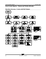
Fault Code Display - Deutz and Perkins Models
88
Z
®
-45 XC
™
• Z
®
-45 HF
Part No. 1268197GT
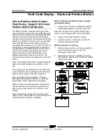
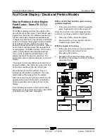
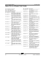
How t o R etrieve Ac ti ve Engine F ault Codes - D eutz TD 2.2 L3 M odels
How to Retrieve Active Engine
Fault Codes - Deutz TD 2.2 L3
Models
The ECM constantly monitors the engine by the
use of sensors on the engine. The ECM also uses
signals from the sensors to initiate sequential fuel
injection and make constant and instantaneous
changes to ignition timing, fuel delivery and throttle
position to maintain the engine's running condition
at its highest efficiency while at the same time
keeping exhaust emissions to a minimum. When a
sensor fails or returns signals that are outside of
set parameters, the ECM will store a fault code in
memory that relates to the appropriate sensor.
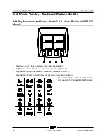
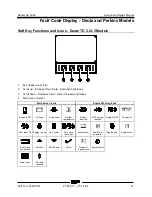
One or more fault LED's will illuminate on the
display located at the ground control box. The
active fault code will also be displayed on the LCD
screen.
If an engine fault occurs that does not result in an
engine shutdown, the engine rpm will go into limp
home mode resulting in the loss of high rpm.
When operating from the platform, if the red
Emergency Stop button is pushed in, the active
fault code(s) will be erased from the display.
Start the engine from the ground control box and
operate various boom functions to verify that an
active engine fault occurs and is shown on the
display.
Note: All faults are stored in the Previous Fault
history menu. These faults will not be erased when
corrective action has been completed.
With an active fault and the engine running:
(preferred method)
1
At the ground controls, activate the auxiliary
pump toggle switch to shut the engine off.
Note: Do not push in the red Emergency Stop
button or turn the key switch to the off position.
2
Press any soft key below the display.
3
Use the scroll up / down keys to check for
multiple engine fault codes.
With the engine not running:
1
At the ground controls, turn the key switch to
ground controls and pull out the red
Emergency Stop button.
2
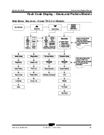
Navigate to the Active Fault Menu and use
the scroll up / down keys to check for multiple
engine fault codes.
Summary of Contents for Genie Z-45 XC
Page 69: ...November 2020 Service and Repair Manual Manifolds Part No 1268197GT Z 45 XC Z 45 HF 57 ...
Page 71: ...November 2020 Service and Repair Manual Manifolds Part No 1268197GT Z 45 XC Z 45 HF 59 ...
Page 73: ...November 2020 Service and Repair Manual Manifolds Part No 1268197GT Z 45 XC Z 45 HF 61 ...
Page 75: ...November 2020 Service and Repair Manual Manifolds Part No 1268197GT Z 45 XC Z 45 HF 63 ...
Page 83: ...November 2020 Service and Repair Manual Manifolds Part No 1268197GT Z 45 XC Z 45 HF 71 ...
Page 143: ...November 2020 Service and Repair Manual 131 Electrical Schematic Ford MSG425 ...
Page 147: ...November 2020 Service and Repair Manual 135 Electrical Schematic Deutz D 2 9 L4 ...
Page 150: ...Service and Repair Manual November 2020 138 Engine Wire Harness Deutz D 2 9 L4 ...
Page 151: ...November 2020 Service and Repair Manual 139 Electrical Schematic Deutz TD 2 2 L3 ...
Page 154: ...Service and Repair Manual November 2020 142 Engine Wire Harness Deutz TD 2 2 L3 Page 1 ...
Page 156: ...Service and Repair Manual November 2020 144 Engine Wire Harness Deutz TD 2 2 L3 Page 2 ...
Page 157: ...November 2020 Service and Repair Manual 145 Electrical Schematic Perkins 404F E22T ...
Page 160: ...Service and Repair Manual November 2020 148 Engine Wire Harness Perkins 404F E22T ...
Page 161: ...November 2020 Service and Repair Manual 149 Electrical Schematic Function Controls ANSI CSA ...
Page 164: ...Service and Repair Manual November 2020 152 Electrical Schematic Function Controls CE ...
Page 165: ...November 2020 Service and Repair Manual 153 Electrical Schematic Platform Overload ...
Page 168: ...Service and Repair Manual November 2020 156 Electrical Schematic Options Wiring Diagram ...
Page 181: ...November 2020 Service and Repair Manual 169 Ground Control Box Switch Panel Wiring Diagram CE ...
Page 185: ...November 2020 Service and Repair Manual 173 Platform Control Box Switch Panel Wiring Diagram ...
Page 192: ...Service and Repair Manual November 2020 180 Platform Control Box Relay Wiring Diagram CE ...
Page 193: ...November 2020 Service and Repair Manual 181 Hydraulic Schematic CE to Z4525XCM 1500 ...
Page 197: ......

