


Service and Repair Manual
September 2016
Schematics
84
Z-40/23N, Z-40/23N RJ
Part No. 1268528
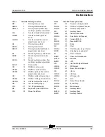
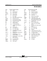
Circuit numbering
1 Circuit numbers consist of three parts: the
circuit prefix, circuit number and circuit suffix.
The circuit prefix indicates the type of circuit.
The circuit number describes the function of
the circuit. The circuit suffix provides an
abbreviation for the number or may be used to
further define the function of this portion of the
circuit. It also may be used to indicate the final
end of the circuit, i.e., LS or limit sw.
2 The circuit number may be used more than
once in a circuit.
For Example:
C 74 PL – This is the circuit for the lockout valve #1.
C stands for control, 74 is the number of the circuit
for the primary #1 lock out valve. PL stands for
Primary Lockout.
S 62 BST – This is the circuit that communicates to
the onboard computers of the machine that the
boom is fully stowed. S stands for safety, 62 is the
number of the circuit for boom stowed and BST
stands for Boom Stowed.
P 48 LP – P stands for power. 48 is the circuit
number for work lamps and LP stands for Lamp.
R 48 LP – R stands for relay. In this case it is the
wire that feeds the relay coil for the work lamp. All
other numbers remain the same.
V61AXR – V stands for valve power. Number
61 stands for axle retracted circuit; AXR stands for
Axle retracted.
R46HRN – R stands for Relay output, supplying
power to the horn (HRN). Number 46 is the circuit
number for the horn.
Circuit prefix
C
Control
D
Data
E
Engine
G
Gauges
N
Neutral
P
Power
R
Relay Output
S
Safety
V
Valve
Summary of Contents for Genie Z-40/23N
Page 63: ...September 2016 Service and Repair Manual Manifolds Part No 1268528 Z 40 23N Z 40 23N RJ 53 ...
Page 111: ...September 2016 Service and Repair Manual 101 Electrical Schematic Chassis ...
Page 114: ...Service and Repair Manual September 2016 104 Electrical Schematic Ground Controls ...
Page 115: ...September 2016 Service and Repair Manual 105 Electrical Schematic Platform Controls ...
Page 118: ...Service and Repair Manual September 2016 108 Ground Control Box Wiring Diagram ...
Page 119: ...September 2016 Service and Repair Manual 109 Platform Control Box Wiring Diagram ...
Page 122: ...Service and Repair Manual September 2016 112 Platform Control Box Wiring Diagram Options ...
Page 123: ...September 2016 Service and Repair Manual 113 Hydraulic Schematic ...
Page 125: ......