background image

April 2019

Fourth Edition - Third Printing

Part No. 

57.0009.0619GT 

                                 GTH-5519                                                                   35 

Operating Instructions

Parking Brake

Use the parking brake switch to apply the parking 
brake before raising the boom or leaving the 
machine.

Push the bottom of the rocker switch to turn the 
parking brake on.

Push the top of the switch to turn the parking 
brake off.

Brake Pedal

Use the brake pedal to control the machine speed 
and to stop the machine motion.

Push and hold the brake pedal to stop the 
machine.

Push and release the brake pedal to control the 
machine speed.

Starting the Engine

1.  Be sure the parking brake is set and the 

transmission control lever is in the neutral 
position.

2.  Insert the key in the ignition switch.

3.  Turn the key until the engine starts.

If the engine fails to start after 30 seconds of 
cranking, determine the cause and repair any 
malfunction. Wait 120 seconds before trying to 
start again.

Starting in Cold Condition

In cold conditions, 20°F / -6°C and below, warm 
the engine for 5 minutes before operating to 
prevent hydraulic system damage.

In extreme cold conditions, 0°F / -18°C and below, 
machines should be equipped with optional cold 
start kits. Attempting to start the engine when 
temperatures are below 0°F / -18°C may require 
the use of a booster battery.

Steer Select

Always position all wheels in line with the machine 
before switching the steering mode.

Do not realign the wheels while driving.

Emergency Exit (if equipped)

Lift up the two levers and remove the wing nuts 
securing the levers to the frame

1

2

3

Summary of Contents for Genie GTH-5519

Page 1: ...Operator s Manual Original Instructions Fourth Edition Third Printing April 2019 Part No 57 0009 0619GT Serial number range GTH 5519 From GTH55M 7009 Tier 4 Interim Tier 4 Final...

Page 2: ...d Lifting Instructions 44 Maintenance 47 Attachments 51 Specifications 57 Load Charts 59 Copyright 2019 by Terex Corporation Fourth Edition Third Printing April 2019 Genie is a registered trademark of...

Page 3: ...ing boom which maybeequippedwithvariousattachmentsforpicking transporting and placing loads with the established load range charts Use of this product in any other way is prohibited and contrary to it...

Page 4: ...pplications and safety Standards and regulatory compliance information QuestionsregardingProductModifications Current owner updates such as changes in machine ownership or changes in your contact info...

Page 5: ...and the safety rules before going on to the next section 2 Always perform a pre operation inspection 3 Always perform function tests prior to use 4 Inspect the workplace 5 Only use the machine as it w...

Page 6: ...ds published by the American National Standards Institute and the IndustrialTruckStandardsDevelopmentFoundation These standards are updated on a regular basis with addenda It is recommended that you p...

Page 7: ...er to load charts and manual Tip over hazard Always wear seat belt Keep load low Crush hazard Crush hazard Work platform use Burn hazard Do not loosen cap until cool Keep away from moving parts No smo...

Page 8: ...lease of hot fluid under pressure can result in death or serious injury Do not loosen cap until cool 1263543 215268 A Fall Hazard Falling can result in death or serious injury When lifting personnel o...

Page 9: ...er lines will result in death or serious injury Stay clear of machine 214418 82558 B Injection Hazard Escaping fluid under pressure can penetrate skin causing serious injury Relieve pressure before di...

Page 10: ...clear of machine during operation WARNING 237598 97667 215268 237601 214418 1263543 97667 214418 97602 237598 237605 237605 237605 A WARNING Burn Hazard Release of hot fluid under pressure can result...

Page 11: ...th electric power lines will result in death or serious injury Stay clear of machine 214418 82558 B Injection Hazard Escaping fluid under pressure can penetrate skin causing serious injury Relieve pre...

Page 12: ...o not exceed the rated capacity for each configuration Do not raise the boom unless the machine is level The machine level indicatorshouldbeatzerodegrees Do not raise a load and then drive to position...

Page 13: ...hine equipment operator skill load position tire inflation machine speed etc Additionally tip over of a machine is dependent in large part upon operator inputs such as the speed and smoothness of the...

Page 14: ...tions Operators must comply with employer job site and governmental rules regarding use of personal protective equipment Do not drive the machine directly up to anyone Do not rely on the rear proximit...

Page 15: ...components under any cover will cause serious injury Only trained maintenance personnel should access compartments Access by the operator is only advised when performing a pre operation inspection All...

Page 16: ...oreperformingservice Keep clear of moving parts during machine operation Burn Hazards Allow hot surfaces to cool before touching or servicing Explosion and Fire Hazards Do not start the engine if you...

Page 17: ...see below For power lines over 1000kV the minimum clearance distance must be established by the utility owner or operator or by a registered professional engineer who is a qualified person with respec...

Page 18: ...acid spills with baking soda and water Explosion Hazards Keep sparks flames and lighted tobacco away from batteries Batteries emit explosive gas Electrocution Hazard Avoid contact with electrical ter...

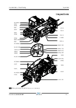
Page 19: ...Cab 8 Hydraulic oil level gauge 9 Engine 10 Forks 11 Seat belt 12 Seat 13 Brake pedal 14 Accelerator pedal 15 Transmission control lever 16 Right rear view mirror 17 Operators manual storage 18 Load...

Page 20: ...positioned at the end of the transmission control lever up to machine serial number GTH55M 10886 The horn button 2 is positioned at the centre of the steering wheel from machine serial number GTH55M...

Page 21: ...ings back to pos I automatically 8 Instrument panel 9 Control handle Pull the control handle back and the boom will raise Push the control handle forward and the boom will lower Push the control handl...

Page 22: ...h to enable the coupling or the release of the attachment managed by the control lever 20 A C switch if equipped Push the switch to turn the A C on Release the switch to turn the A C off 21 Cab heater...

Page 23: ...ugs preheating indicator light 7 Not active 8 Not active 9 Not active 10 Engine air filter restricted indicator light 11 Engine Alert indicator light 12 Engine Critical Fault indicator light 13 Not ac...

Page 24: ...is clogged proceed with cleaning or changing the air filter cartridge 11 Engine Alert indicator light Thislightflashestowarnofaproblemwiththeengine To identify the problem see the two sections Engine...

Page 25: ...ction is designed to discover if anything is apparentlywrongwithamachinebeforetheoperator performs the function tests Thepre operationinspectionalsoservestodetermine ifroutinemaintenanceproceduresarer...

Page 26: ...ngpartsandunauthorized modifications Electrical components wiring and electrical cables Hydraulic hoses fittings cylinders and manifolds Fuel and hydraulic tanks Drive motors and drive hubs Boom wear...

Page 27: ...5 Only use the machine as it was intended Function Test Fundamentals The function tests are designed to discover any malfunctions before the machine is put into service Theoperatormustfollowthestep b...

Page 28: ...tion switch 11 Turn the key to start the engine Result The engine should not start 12 Set the transmision control lever in gear 13 Push the bottom of the parking brake switch to turn it on 14 Insert t...

Page 29: ...the rear wheels should turn in the same direction as the steering wheel Test the Transmission and Brakes 29 Be sure the boom is fully lowered and retracted 30 Step on the brake pedal Push the top of t...

Page 30: ...5 meters in front of it Do not perform the function test if there are people behind the machine 42 Settheparkingbrake placethetransmissioninto neutral and start the engine Press and hold the brakeped...

Page 31: ...n helps the operator determineiftheworkplaceissuitableforsafemachine operation Itshouldbeperformedbytheoperatorprior to moving the machine to the workplace Itistheoperator sresponsibilitytoreadandreme...

Page 32: ...1 09 4618 1691 Label Testing Ports 1 09 4618 0776 Label Door internal unlock system 1 09 4618 1025 Label Upper Door External Unlock System 1 09 4618 1742 Label Emergency Exit Handles 1 1258639 Cosmeti...

Page 33: ...215268 09 4618 0643 82366 09 4618 0644 215267 214418 09 4618 0644 237601 214418 1263543 09 4618 0643 97602 28159 237598 237598 97667 214418 09 4618 1691 97667 09 4618 0776 09 4618 1742 237971 237605 0...

Page 34: ...l Lifting Anchoring 1 09 4618 1691 Label Testing Ports 1 09 4618 0776 Label Door internal unlock system 1 09 4618 1025 Label Upper Door External Unlock System 1 09 4618 1742 Label Emergency Exit Handl...

Page 35: ...268 09 4618 0643 82366 09 4618 0644 215267 214418 09 4618 0644 237601 97667 214418 1263543 09 4618 0643 97602 826345 28159 237598 237598 97667 214418 09 4618 1691 97667 09 4618 0776 09 4618 1742 23797...

Page 36: ...als A variable reach rough terrain forklift truck is defined as a wheeled type truck designated primarily as a fork truck with a pivoted boom which may be equipped with attachments for lifting materia...

Page 37: ...osition 2 Insert the key in the ignition switch 3 Turn the key until the engine starts If the engine fails to start after 30 seconds of cranking determine the cause and repair any malfunction Wait 120...

Page 38: ...vel Step on the service brake pedal before putting the transmission into gear To drive forward move the transmission control lever toward you and move it up To drive in reverse move the transmission c...

Page 39: ...to the loading or pick point so that the weight of the load will meet the load chart specifications 2 Divide the load into smaller pieces so that each piece meets the load chart specifications 3 Obtai...

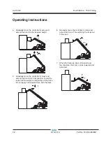
Page 40: ...troller to lower and extend the boom into final position Lower the load until the weight is completely off the forks Do not apply a downward force with the forks Operating Instructions 6 Gradually mov...

Page 41: ...Third Printing Part No 57 0009 0619GT GTH 5519 39 Operating Instructions Controller movements Control handle only Control handle only with yellow thumb switch A OPTIONAL 09 4618 1688 Control handle on...

Page 42: ...ame 9 Refit mechanical locking pin fixing it with its safety split pin 10 Re couple the connectors of the attachment if any Version with hydraulic locking optional 1 Drive to the place where you will...

Page 43: ...e machine directly to the starter or the starter solenoid Serious injury or death could result from the machine moving forward or backward To avoid personal injury when jump starting with another mach...

Page 44: ...s signal person and mirrors and is not intended to be used as the sole method of collision avoidance It should be used in conjunction with established safety programs and procedures to augment the saf...

Page 45: ...e the parking brake is disabled To unlock the negative brake of a faulty machine 1 On both sides unscrew the nuts 5 2 Screw in the brake release bolts 6a and 6b 1 2 turn at a time in sequence until th...

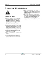
Page 46: ...in preparing loading and securing construction and lifting equipment for international shipment Only qualified operators should move the machine on or off the truck The transport vehicle must be park...

Page 47: ...ed Prior to loading level the telehandler and retract the boom Use a spotter to load and unload the telehandler Keep the boom as low as possible when loading and unloading Set the parking brake Securi...

Page 48: ...the crane capacity loading surfaces and straps or lines are sufficient to withstand the machine weight See the serial label for the machine weight Lifting Instructions Fully lower and retract the boom...

Page 49: ...ar at the beginning of a maintenance procedure it conveys the meaning below Indicates that tools will be required to perform this procedure Indicates that new parts will be required to perform this pr...

Page 50: ...sually inspect the sight gauge located behind the cab Result The hydraulic oil level should be halfway in the sight gauge 3 Add oil as needed Do not overfill Hydraulic oil specifications Hydraulic Oil...

Page 51: ...and extremely hot Use caution when removing cap and adding fluids Check the Tire Pressure Tip over hazard An over inflated tire can explode which may compromise machine stability and cause the machine...

Page 52: ...formance and operational safety Improper fluid levels or damaged cables and connections can result in component damage and hazardous conditions Electrocution hazard Contact with hot or live circuits m...

Page 53: ...ionary As a suspended load moves the load center can change As a result extreme caution in transporting and lifting or placing the load must be observed to minimize the potential for the load to move...

Page 54: ...s as the load center will move towards the tipping line thereby reducing stability Only climb or descend inclines with extreme care as the load center will move towards the tipping line thereby reduci...

Page 55: ...ly and gradually raise the boom and load making sure to keep the load and boom as close to the ground as practical Be sure that all boom and attachment movements are performed as slow as practical to...

Page 56: ...ntil the rigging and tethers can be removed Signal Person from 1926 1419 Per OSHA CFR 1926 1419 a signal person is required when The point of operation meaning the load travel or the area near or at l...

Page 57: ...sed RAISE THE BOOM AND LOWER THE LOAD With arm extended horizontally to the side and thumb pointing up fingers open and close while load movement is desired DOG EVERYTHING Hands held together at waist...

Page 58: ...in the initial connection of a load to a component or structure and are within the fall zone all of the following criteria must be met The materials being hoisted must be rigged to prevent unintention...

Page 59: ...apacity maximum height with 24 in 61 cm load center 4 400 lbs 1 995 kg Lift capacity maximum reach with 24 in 61 cm load center 2 000 lbs 907 kg Maximum lift capacity 5 500 lbs 2 495 kg Drive speed ma...

Page 60: ...l 2019 58 GTH 5519 Part No 57 0009 0619GT Fourth Edition Third Printing Approximate detection range Minimum rear proximity sensor detection height is 2 ft 0 6 m Rear proximity Sensor Range Specificati...

Page 61: ...d Capacity Field Calculations Always center the load on the forks Position the load so that it is completely against the back of the fork frame Fork length should always be at least 2 3 the load lengt...

Page 62: ...rts 0 ft 5 ft 10 ft 0 ft 0 m 5 ft 1 52 m 10 ft 3 05 m 15 ft 4 57 m 20 ft 6 10 m 0 ft 0 m 5 ft 1 52 m 10 ft 3 05 m 5 5 0 0 l b s 2 4 9 5 k g 4400 lbs 1995 kg 3000 lbs 1361 kg 2000 lbs 907 kg 1900 lbs 8...

Page 63: ...April 2019 Fourth Edition Third Printing Part No 57 0009 0619GT GTH 5519 61 Load Charts GTH 5519 Scrap Grapple Bucket OPT 48 48 INC GTH 5519 60 inch Forks optional 48 inch Forks 48 inch cubing Tines G...

Page 64: ...Part No 57 0009 0619GT Fourth Edition Third Printing GTH 5519 Universal Attachment Adapter GTH 5519 Rotating Or Side Shift Fork Carriage Standard Fork Tines Load Charts 09 4618 GT 09 46 GTH ROTATING...

Page 65: ...ng Part No 57 0009 0619GT GTH 5519 63 GTH 5519 Truss Boom GTH 5519 Side Shift Fork Carriage 60 Fork Tines Load Charts 09 461 GT 09 4 GT SIDE SHIF 2800 lbs 1270 kg 4 5 0 0 l b s 2 0 4 1 k g 2300 lbs 10...

Page 66: ...April 2019 64 GTH 5519 Part No 57 0009 0619GT Fourth Edition Third Printing Load Charts GTH 5519 Shackle 09 4618 1867 GTH 5519...

Page 67: ...exhaust do not idle the engine except as necessary service your equipment and vehicle in a well ventilated area and wear gloves or wash your hands frequently when servicing your equipment or vehicle a...

Reviews:

Related manuals for Genie GTH-5519