


Service and Repair Manual
June 2021
Ground Controls
64
GS
™
-84 • GS
™
-90
Part No. 1306587GT
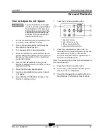
How to Adjust the Steer Speed
How to Adjust the Steer Speed
1 Pull out the red Emergency stop button to the
on position at the platform controls.
2 Push in the ground controls red Emergency
Stop button to the off position.
3 Turn the key switch to ground controls.
4 Press and hold both the blue platform up and
yellow platform down buttons. Pull out the red
Emergency Stop button to the on position at
the ground controls.
Result: TUNE SPEEDS is showing in the
diagnostic display window. The ECM is now in
programming mode.
5 Press the lift function enable button.
6 Use the yellow platform down arrow to scroll
to steering speed.
Result: STEERING SPEED is showing in the
diagnostic display window.
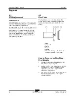
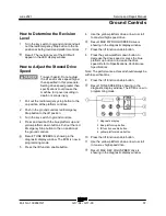
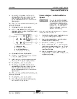
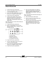
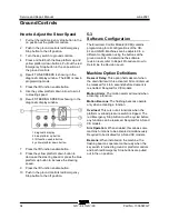
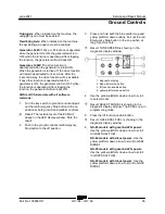
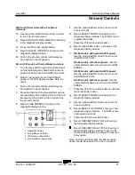
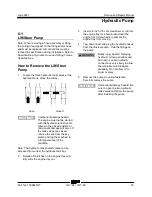
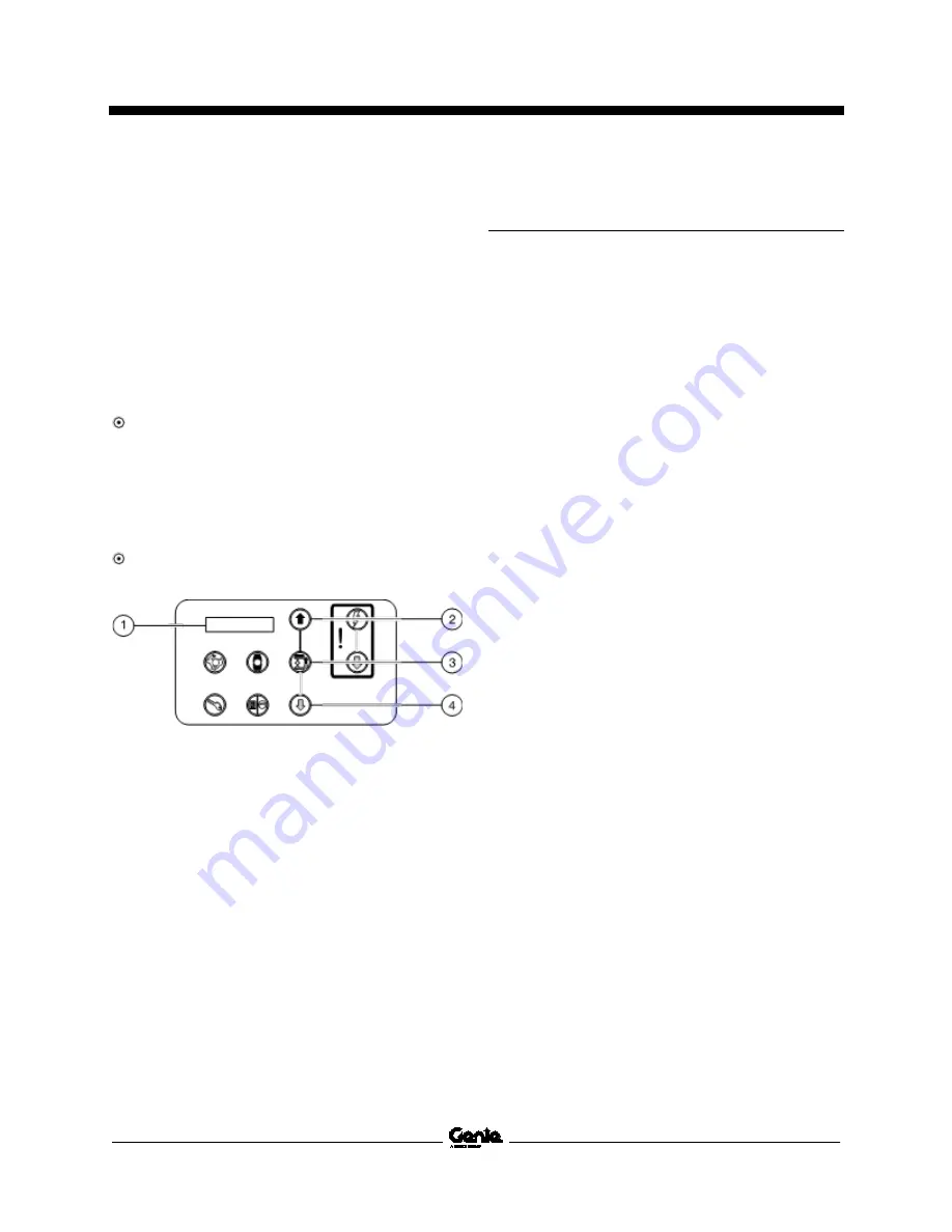
1 diagnostic display
2 blue platform up button
3 lift function enable button
4 yellow platform down button
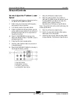
7 Press the lift function enable button.
8 Press the yellow platform down button to
decrease the steering speed or press the blue
platform up button to increase the steering
speed.
9 Press the lift function enable button.
10 Push in the ground controls red Emergency
Stop button to the off position.
5-3
Software Configuration
The Electronic Control Module (ECM) contains
programming for all configurations of the GS-
84 and GS-90. Machines can be adjusted to a
different configuration using the buttons at the
ground controls. To determine the software
revision level, refer to Repair Procedure,
How to
Determine the Revision Level
.
Machine Option Definitions
Descent Delay:
This option halts descent when
the down limit switch is activated. All controls must
be released for 4 to 6 seconds before descent is
re-enabled. Required for CE models.
Motion Alarm
: The motion alarm will sound when
activating a function.
Motion Beacons
: The flashing beacons operate
only when activating a function.
Overload:
This cuts out all functions when the
platform overload pressure switch is tripped. The
red Emergency Stop button must be cycled before
any function can be resumed. Required for AS and
CE models.
Sim Operation:
When enabled, this allows some
machine functions to be activated simultaneously.
Required to be disabled for AS and CE models.
Beacons
: When installed on the machine, the
flashing beacons operate continuously when the
key switch is turned to ground or platform controls
and both red Emergency Stop buttons are pulled
out to the on position.
Summary of Contents for Genie GS-3384
Page 185: ...June 2021 Service and Repair Manual 171 Ford MSG 425 Engine Wire Harness...
Page 188: ...Service and Repair Manual June 2021 174 Deutz D 2 9 L4 Engine Wire Harness...
Page 189: ...June 2021 Service and Repair Manual 175 Deutz TD 2 2 L3 Engine Wire Harness...
Page 192: ...Service and Repair Manual June 2021 178 Deutz TD 2 2 L3 Engine Wire Harness...
Page 193: ...June 2021 Service and Repair Manual 179 Hydraulic Schematic...
Page 194: ...Service and Repair Manual June 2021 180 GS 84 GS 90 Part No 1306587GT Hydraulic Schematic...
Page 195: ...June 2021 Service and Repair Manual Part No 1306587GT GS 84 GS 90 181 Hydraulic Schematic...
Page 196: ...Service and Repair Manual June 2021 182 Hydraulic Schematic...
Page 197: ...June 2021 Service and Repair Manual 183 Electrical Schematic Ford Engine Models ANSI CSA...
Page 200: ...Service and Repair Manual June 2021 186 Electrical Schematic Ford Engine Models ANSI CSA...
Page 201: ...June 2021 Service and Repair Manual 187 Electrical Schematic Deutz Engine Models ANSI CSA...
Page 204: ...Service and Repair Manual June 2021 190 Electrical Schematic Deutz Engine Models ANSI CSA...
Page 206: ...Service and Repair Manual June 2021 192 Electrical Schematic SCON ANSI CSA...
Page 207: ...June 2021 Service and Repair Manual 193 Electrical Schematic Ford Engine Models AS CE...
Page 210: ...Service and Repair Manual June 2021 196 Electrical Schematic Ford Engine Models AS CE...
Page 211: ...June 2021 Service and Repair Manual 197 Electrical Schematic Deutz Engine Models AS CE...
Page 214: ...Service and Repair Manual June 2021 200 Electrical Schematic Deutz Engine Models AS CE...
Page 217: ......


