background image

Specification 


10 


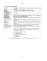
3.8  APPLICABLE STANDARDS 


BS 4884-1 

This document conforms to BS4884-1 1992 Specification for presentation of essential 
information. 

BS 4884-2 

This document conforms to BS4884-2 1993 Guide to content 

BS 4884-3 

This document conforms to BS4884-3 1993 Guide to presentation 

BS EN 60068-2-1 

 (Minimum temperature)


-30

°

C (-22

°

F) 

BS EN 60068-2-2 

 (Maximum temperature)


+70

°

C (158

°

F) 

BS EN 60950


Safety of information technology equipment, including electrical business equipment 

BS EN 61000-6-2


EMC Generic Immunity Standard (Industrial) 

BS EN 61000-6-4


EMC Generic Emission Standard (Industrial) 

BS EN 60529


(Degrees of protection 
provided by enclosures)


IP65 (front of module when installed into the control panel with the optional sealing 
gasket)  
IP42 (front of module when installed into the control panel WITHOUT being sealed to 
the panel) 

UL508  
NEMA rating 

(Approximate) 

12 (Front of module when installed into the control panel with the optional sealing 
gasket).  
2 (Front of module when installed into the control panel WITHOUT being sealed to 
the panel) 

IEEE C37.2 

(Standard Electrical Power 
System Device Function 
Numbers and Contact 
Designations)


Under the scope of IEEE 37.2, 

function numbers can also be used to represent 

functions in microprocessor devices and software programs

The TT2 series controller is device number 11L-334 (Multifunction device protecting 
Line (generator) – TT2 series module).  
 
As the module is configurable by the generator OEM, the functions covered by the 
module will vary. Under the module’s factory configuration, the device numbers 
included within the module are : 
 
2 – Time delay starting or closing relay 
30 – annunciator relay 
42 – Running circuit breaker 
62 – time delay stopping or opening relay 
74– alarm relay 
81 – frequency relay 
86 – lockout relay 


In line with our policy of continual development, Terasaki, reserve the right to change specification without notice. 

Summary of Contents for TemTransfer 2

Page 1: ...TemTransfer 2 Controller Operators Manual Issue 1 12 TemTransfer 2 ATS Control Module Document Number 057 154...

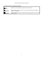
Page 2: ...ights an essential element of a procedure to ensure correctness CAUTION Indicates a procedure or practice which if not strictly observed could result in damage or destruction of equipment WARNING Indi...

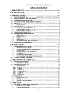
Page 3: ...LE STANDARDS 10 4 INSTALLATION 11 4 1 TERMINAL DESCRIPTION 11 4 1 1 DC SUPPLY AND OUTPUT C 11 4 1 2 OUTPUTS D E AND FUNCTIONAL EARTH 11 4 1 3 DIGITAL INPUTS 11 4 1 4 LOAD SWITCHING AND S2 SENSING 12 4...

Page 4: ...NG DIAGRAM 31 6 4 5 2 CHECK SYNCHRONISING IS ENABLED 32 6 4 5 2 1 TRANSFER TO S2 32 6 4 5 2 2 TRANSFER TO S1 32 6 4 5 2 3 LOAD SHED INPUT 32 6 4 5 2 4 TIMING DIAGRAM 32 7 MODULE DISPLAY 33 7 1 BACKLIG...

Page 5: ...status and fault conditions automatically transferring the load to the backup supply in case of mains supply failure The LCD display indicates the status The powerful microprocessor contained within t...

Page 6: ...Specification 6 3 SPECIFICATIONS At the time of this document production there have been no revisions to the module hardware...

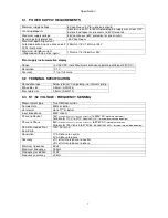
Page 7: ...ERMINAL SPECIFICATION Connection type Screw terminal rising clamp no internal spring Min cable size 0 5mm AWG 24 Max cable size 2 5mm AWG 10 3 3 S1 S2 VOLTAGE FREQUENCY SENSING Measurement type True R...

Page 8: ...rcuit voltage 12V 1V 3 5 OUTPUTS 3 5 1 S1 S2 LOADING OUTPUTS A B Number 2 Configurable outputs A B Type Volts free contacts Output C Normally closed Output D Normally open Rating 8A 250V AC resistive...

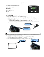
Page 9: ...clip are inside their allotted slots Turn the fixing clip screws clockwise until they make contact with the panel fascia Turn the screws a little more to secure the module into the panel fascia Care...

Page 10: ...L508 NEMA rating Approximate 12 Front of module when installed into the control panel with the optional sealing gasket 2 Front of module when installed into the control panel WITHOUT being sealed to t...

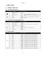
Page 11: ...ut E 1 0mm AWG 18 10 System Earth 1 0mm AWG 18 4 1 3 DIGITAL INPUTS PIN No DESCRIPTION CABLE SIZE NOTES 11 Input A 1 0mm AWG 18 Configurable input Connects to plant supply negative 12 Input B 1 0mm AW...

Page 12: ...onnect to S2 L1 U output AC Recommend 2A fuse 27 S2 L2 V voltage monitoring 1 0mm AWG 18 Connect to S2 L2 V output AC Recommend 2A fuse 28 S2 31 W voltage monitoring 1 0mm AWG 18 Connect to S2 L3 W ou...

Page 13: ...re the CT is rated for the burden of the TemTransfer 2 series controller the cable length being used and any other equipment sharing the CT If in doubt consult your CT supplier NOTE When not required...

Page 14: ...For distances over 5m it is possible to use a third party USB extender Typically they extend USB up to 50m yds The supply and support of this type of equipment is outside the scope of Terasaki CAUTIO...

Page 15: ...te system Genset manufacturers and panel builders may use these diagrams as a starting point however you are referred to the completed system diagram provided by your system manufacturer for complete...

Page 16: ...section details the function and meaning of the various controls on the module Select Mode Common Alarm Indicator Display Scroll button Toggle S1 load switch Select auto Mode Main status display Sele...

Page 17: ...Description of Controls 17 S2 On load S1 On load S2 Available S1 Available...

Page 18: ...t guide to the module s operation 5 1 1 STANDBY OPERATION NOTE For further details see the section entitled OPERATION elsewhere in this manual NOTE If module power is removed it will remember the last...

Page 19: ...the status display When scrolling manually the display will automatically return to the Status page if no buttons are pressed for the duration of the configurable LCD Page Timer If an alarm becomes ac...

Page 20: ...ny current alarms Example English Icon 5 2 1 3 EVENT LOG Displays the entire event log Example 5 2 1 4 LCD INDICATORS Shows the status of the configurable LCD indicators Example 5 2 1 5 SCHEDULE Shows...

Page 21: ...age S1 S1 or S2 voltage has risen above the pre set pre alarm setting Under voltage S1 S1 or S2 voltage has fallen below the pre set pre alarm setting Over frequency S1 S1 or S2 frequency has risen ab...

Page 22: ...has fallen below the preset level S2 as Mains Over Voltage S2 S1 output voltage has risen above the preset level S1 Under Frequency S1 S1 output frequency has fallen below the preset level S1 Over Fre...

Page 23: ...vent the module from returning load the S1 until instructed For further details please see the more detailed description of Mode operation elsewhere in this manual This mode allows manual control of t...

Page 24: ...t by the start run output If the generator fails to become available before the generator failure timer expires This is indicated on the LCD display but the starting signal remains active 6 1 3 S2 ON...

Page 25: ...buttons are pressed when configured The module mode is changed to STOP RESET or AUTO mode The system may then transfer back to mains supply automatically if conditions are suitable 6 2 4 TRANSFER BUT...

Page 26: ...isplay which shows Fail to Start S2 is seen as available once the supply is within limits if configured as a mains supply or had achieved loading voltage and frequency if configured as a generator 6 3...

Page 27: ...ome from a number of sources S1 supply out of limits Activation of an auxiliary input that has been configured to remote start on load Activation of the inbuilt exercise scheduler if configured for on...

Page 28: ...ng the RS232 or RS485 interface 6 3 3 2 STARTING SEQUENCE To allow for false start load requests such as S1 brownouts the start delay timer begins There are individual start delay timers for each of t...

Page 29: ...ntil S2 is seen as available S2 is seen as available S2 is seen as available S2 is seen as available This prevents This prevents This prevents This prevents loading loading loading loading to a suppl...

Page 30: ...LOAD INHIBIT Activation of an input configured to S1 load inhibit or S2 load inhibit inputs cause the corresponding breaker to be opened immediately No other change in function will occur When the inp...

Page 31: ...er occurs first When the S2 Closed Auxiliary indicates the generator breaker has opened the transfer timer begins When the transfer timer expires the module attempts to close S1 breaker by energising...

Page 32: ...performs a non sync transfer sync transfer sync transfer sync transfer 6 4 5 2 1 TRANSFER TO S2 When the module is about to transfer from S1 to S2 it activates the check sync function When the S1 and...

Page 33: ...ach loading frequency S2 is running and within under over frequency trip points but has failed to reach the configured Loading Frequency hence it is unfit to take load 7 2 2 S1 S1 alarms signal that t...

Page 34: ...ning alarms only The module displays the fault but no further action is taken Under Voltage warning The battery supply is below the configured Under Voltage warning level Under Voltage warning The bat...

Page 35: ...e allows the operator limited customising of the way the module operates Use the module s navigation buttons to traverse the menu and make value changes to the parameters Increase value next item Edit...

Page 36: ...in the current page When viewing the parameter to be changed press the button The value begins to flash Press or to adjust the value to the required setting Press to save the current value the value c...

Page 37: ...524 Scheduler Bank 1 Event 7 Duration hh mm 525 Scheduler Bank 1 Event 8 Day 1 7 Day 1 Monday 526 Scheduler Bank 1 Event 8 Start Time hh mm 527 Scheduler Bank 1 Event 8 Duration hh mm 528 Scheduler Ba...

Page 38: ...an on load test active or off load test inactive Press to move to the next item Review the current setting and choose if the Scheduler is to perform a weekly schedule repeats every 7 days or monthly r...

Page 39: ...NANCE SPARES REPAIR AND SERVICING The TemTransfer 2 Series controller is designed to be Fit and Forget As such there are no user serviceable parts within the controller In the case of malfunction you...

Page 40: ...use electrical and electronic equipment you must store collect treat recycle and dispose of WEEE separately from your other waste 11 2 ROHS RESTRICTION OF HAZARDOUS SUBSTANCES Directive 2002 95 EC 20...

Page 41: ...update of the controller 12 1 2 PC TO CONTROLLER DIRECT CONNECTION To connect a TemTransfer 2 module to a PC the following items are required Terasaki series module Configuration Suite software Suppl...

Page 42: ...ment enclosure is tilted at an angle up to 15 from its normal position drops falling at an angle 3 Protected against ingress of solid objects with a diameter of more than 2 5 mm Tools wires etc with a...

Page 43: ...P31 Provides a degree of protection against limited amounts of falling water and dirt 3 IP64 Provides a degree of protection against windblown dust rain and sleet undamaged by the formation of ice on...

Page 44: ...This page is intentionally left blank 44...

Page 45: ...Appendix 45...

Reviews: