background image

ENGINE--G/LPG

6--21

800/810 MM337 (8--97)

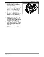
GOVERNOR ACTUATOR (LSG ENGINE)

The electronic governor controls the engine

speed. The governor consists of an ignition

control assembly, a control box, and an actuator

mounted to the carburetor. The ignition control

assembly and control box regulate the actuator,

which in turn controls the throttle.

The electronic governor is factory set and is not

user serviceable.

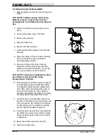
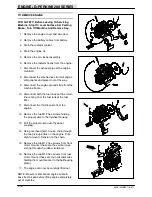
TO REPLACE GOVERNOR ACTUATOR

(LSG ENGINE)
FOR SAFETY: Before Leaving Or Servicing

Machine; Stop On Level Surface, Set Parking

Brake., Turn Off Machine And Remove Key.

1. Stop the engine and set the machine parking

brake.

2. Open the engine cover and side door.

3. Disconnect the battery cables.

WARNING

:

Always disconnect battery

cables from machine before working

on electrical components.

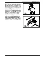
4. Disconnect the two wires leading to the top

of the governor actuator.

5. Pop the rod end of the throttle rod off the

ball on the actuator arm.

6. Remove the four screws and nuts holding

the actuator to the mount bracket.

7. Remove the arm from the actuator shaft and

install it on the new actuator in the same

orientation.

8. Position the new actuator on the mount

bracket and install the four screws and nuts.

Tighten to 9 -- 13 Nm (7 -- 10 ft lb).

9. Snap the throttle rod onto the ball on the

actuator arm.

10. Reconnect the two wires on top of the

actuator. Reconnect the battery cables.

11. Start the machine and check the new

actuator for proper operation. See TO

ADJUST GOVERNOR instructions.

Summary of Contents for 800

Page 1: ...800 810 Service Manual MM337 Rev 04 6 01 Gas LP Diesel ...

Page 2: ...tor replacement repair cylinder replacement repair pump replacement repair filter replacement and hydraulics troubleshooting Engine G LPG Air filter replacement oil changing cooling system maintenance repair fuel system maintenance repair governor adjustment repair engine repair engine troubleshooting and engine repairs Engine D Perkins 200 Series Air filter replacement oil changing cooling system...

Page 3: ...RFORMANCE 1 9 POWER TYPE GAS LP 1 10 POWER TYPE DIESEL 1 11 STEERING 1 12 ELECTRICAL SYSTEM 1 12 800 810 ELECTRICAL 1 12 HYDRAULIC SYSTEM 1 12 HYDRAULIC PUMPS CHAR LYNN 1 12 HYDRAULIC MOTORS GAS LP 1 13 HYDRAULIC MOTORS DIESEL 1 13 BRAKING SYSTEM 1 13 TIRES 1 13 MAINTENANCE GAS LPG 1 14 MAINTENANCE CHART 1 14 MAINTENANCE DIESEL 1 16 MAINTENANCE CHART 1 16 HARDWARE INFORMATION 1 18 STANDARD BOLT TO...

Page 4: ...GENERAL INFORMATION 1 2 800 810 MM337 8 97 ...

Page 5: ...ot carry passengers on machine always follow safety and traffic rules report machine damage or faulty operation immediately 5 Before leaving or servicing machine stop on level surface set parking brake turn off machine and remove key 6 When servicing machine avoid moving parts do not wear loose jackets shirts or sleeves block machine tires before jacking machine up jack machine up at designated lo...

Page 6: ...LIFT ARMS LABEL LOCATED ON BOTH HOPPER LIFT ARMS HOPPER SUPPORT BAR LABEL LOCATED ON THE HOPPER LIFT ARMS CROSS TUBE AND ON BOTH HOPPER LIFT ARMS NOISE LABEL LOCATED ON THE FRONT PANEL OF THE OPERATOR COMPARTMENT EMISSIONS LABEL LOCATED ON THE FRONT PANEL OF THE OPERATOR COMPARTMENT 07623 FOR SAFETY LABEL LOCATED ON THE FRONT PANEL OF THE OPERATOR COMPARTMENT ENGINE FAN AND BELT LABEL LOCATED ON T...

Page 7: ...pushed or towed This valve allows a disabled machine to be moved for a very short distance and at a speed to not exceed 1 6 kp h 1 mph The machine is NOT intended to be pushed or towed a long distance or at a high speed ATTENTION Do not push or tow machine for a long distance and without using the bypass valve or the machine hydraulic system may be damaged Turn the bypass valve 90_ from the normal...

Page 8: ...ne 2 If the loading surface is not horizontal or is higher than 380 mm 15 in from the ground use a winch to load machine If the loading surface is horizontal AND is 380 mm 15 in or less from the ground the machine may be driven onto the truck or trailer 3 To winch the machine onto the truck or trailer attach the winching chains to the rear tie down locations The rear tie down locations are through...

Page 9: ...o center the machine 6 Set the parking brake and block the machine tires Tie down the machine to the truck or trailer before transporting The two front tie down locations are through the U bolt section of the main frame in front of the wheels The two rear tie down locations are through the U bolt section of the main frame under the side bumpers toward the rear 7 If the loading surface is not horiz...

Page 10: ...ions are the flat bottom edge of the machine frame next to the front tires The rear jacking location is the middle of the rear bumper FOR SAFETY When Servicing Machine Block Machine Tires Before Jacking Machine Up FOR SAFETY When Servicing Machine Jack Machine Up At Designated Locations Only Block Machine Up With Jack Stands STORING MACHINE Before storing the machine for an extended period of time...

Page 11: ...rowt brush diameter 205 mm 8 in Power Throwt brush length 1170 mm 46 in Side brush diameter 65 mm 26 in Sweeping path width 1270 mm 50 in Sweeping path width with side brush 1675 mm 66 in Main brush pattern width 50 to 65 mm 2 0 to 2 5 in Hopper weight capacity 907 2 kg 2000 lb Hopper volume capacity 849 5 L 30 cu ft Dust filter area 17 7 m2 190 sq ft GVWR 4068 kg 8970 lb Ceiling height minimum du...

Page 12: ...ype spark 4 Natural 4 96 mm 3 78 in 80 mm 3 126 in 96 mm 3 78 in Fuel Cooling system Electrical system Gasoline 87 octane minimum unleaded Fuel tank 45 5 L 12 gal Water ethylene glycol antifreeze 12 V nominal LPG F l t k 15 k 33 lb Total 16 7 L 4 4 gal 50 A alternator Fuel tank 15 kg 33 lb Radiator 6 2 L 1 6 gal Start governed speed Low governed speed High governed speed 1350 50 rpm LSG 1475 50 rp...

Page 13: ...gnition Cycle Aspiration Cylinders Bore Stroke Perkins 704 30 Series Piston Diesel 4 Natural 4 97 mm 3 8 in 100 mm 3 9 in Displacement Net power governed Net power maximum 3 0 L 183 cu in 44 8 kw 63 hp 2400 rpm 47 kw 63 hp 2400 rpm Fuel Cooling system Electrical system Diesel Fuel tank 45 5 L 12 gal Water ethylene glycol antifreeze 12 V nominal Total 13 6 L 3 6 gal 50 A alternator std 100 A altern...

Page 14: ...p draw cold 185 10Volts Amp draw hot 155 11 5 Standard alternator Diesel Gas LP Output 50 amps 5000 rpm Volts 14 5 HYDRAULIC SYSTEM System Capacity Fluid Type Hydraulic reservoir 47 3 L 12 5 gal TENNANT part no 65869 above 7_ C 45_ F Hydraulic total 56 8 L 15 gal TENNANT part no 65870 below 7_ C 45_ F HYDRAULIC PUMPS CHAR LYNN Propelling 23 2 GPM 88 L min 4500 PSI Relief 31027 kPa Normal throttle ...

Page 15: ...sh Char lynn 385 RPM Side brush Char lynn 78 RPM Vacuum fan Barnes 8500 RPM Propelling Char lynn 150 RPM BRAKING SYSTEM Type Operation Service brakes Hydraulic drum brakes 2 one per front wheel foot brake master cylinder activated Parking brake Utilize service brakes cable actuated TIRES Location Type Size Pressure Front 2 Pneumatic 6 5 x 23 5 in 690 758 kPa 100 110 psi Rear 1 Pneumatic 6 5 x 23 5...

Page 16: ...2 Engine crankcase Check oil level EO 1 13 Brush compartment skirts Check for damage wear and adjustment 6 15 Hopper lip skirts Check for damage wear and adjustment 3 13 Main brush Check for damage wear and adjustment 1 Check brush pattern 1 1 Side brush Check for damage wear and adjustment 1 Check brush pattern 1 2 Hopper dust filter Shake 2 50 Hours 13 Main brush Rotate end for end 1 2 Hopper du...

Page 17: ...lugs 1 Replace PCV valve Replace fuel filters gasoline 8 Cooling system Flush WG 1 4 Brake master cylinder Check fluid level BF 1 800 Hours 6 Hydraulic reservoir Replace filler cap GL y Replace suction strainer GL 1 Change hydraulic fluid HYDO 1 9 Hydraulic fluid filter H Change filter element 1 9 Hydraulic fluid filter H Change filter element 1 12 Engine Clean PCV hoses tubes fit tings 1 Torque i...

Page 18: ...eck oil level EO 1 13 Brush compartment skirts Check for damage wear and adjustment 6 15 Hopper lip skirts Check for damage wear and adjustment 3 13 Main brush Check for damage wear and adjustment 1 Check brush pattern 1 1 Side brush Check for damage wear and adjustment 1 Check brush pattern 1 2 Hopper dust filter Shake 2 50 Hours 13 Main brush Rotate end for end 1 2 Hopper dust filter Check or cl...

Page 19: ...ate SPL 1 400 Hours 12 Fuel filter Engine Replace 1 12 Water separator fuel filter Replace 1 8 Cooling system Flush WG 1 4 Brake master cylinder Check fluid level BF 1 800 Hours 6 Hydraulic reservoir Replace filler cap GL y Replace suction strainer GL 1 Change hydraulic fluid HYDO 1 9 Hydraulic fluid filter H Change filter element 1 9 Hydraulic fluid filter H Change filter element 1 9 Hydraulic ho...

Page 20: ...TORQUE CHART Thread SAE Grade 5 SAE Grade 8 Size Torque ft lb Nm Torque ft lb Nm 0 25 in 7 10 9 14 10 13 14 38 0 31 in 15 20 20 27 20 26 27 35 0 38 in 27 35 37 47 36 47 49 64 0 44 in 43 56 58 76 53 76 72 103 0 50 in 65 85 88 115 89 116 121 157 0 62 in 130 170 176 231 117 265 159 359 0 75 in 215 280 291 380 313 407 424 552 1 00 in 500 650 678 881 757 984 1026 1334 NOTE Decrease torque by 20 when us...

Page 21: ... AND LOCKING COMPOUNDS Thread sealants and locking compounds may be used on this machine They include the following Locktite 515 sealant gasket forming material TENNANT Part No 75567 15 oz 440 ml cartridge Locktite 242 blue medium strength thread locking compound TENNANT Part No 32676 0 5 ml tube Locktite 271 red high strength thread locking compound TENNANT Part No 19857 0 5 ml tube ...

Page 22: ...GENERAL INFORMATION 800 810 MM337 6 01 1 20 ...

Page 23: ...DRAG CHAIN 2 4 BRAKES AND TIRES 2 5 SERVICE BRAKES 2 5 TO REPLACE BRAKE SHOES 2 5 TO ADJUST BRAKES 2 7 FRONT TIRES AND WHEELS 2 8 TO REPACK FRONT WHEEL BEARINGS 2 8 PARKING BRAKE FOOT ACTIVATED 2 9 TO ADJUST FOOT ACTIVATED BRAKE 2 9 PARKING BRAKE HAND ACTIVATED 2 9 TO ADJUST HAND ACTIVATED BRAKE 2 9 REAR TIRE AND WHEEL AND WHEEL SUPPORT 2 10 TO REPLACE REAR WHEEL HOUSING PIVOT BEARINGS 2 11 ...

Page 24: ...CHASSIS 2 2 800 810 MM337 8 97 ...

Page 25: ... ASSEMBLY 1 Tilt the seat assembly forward and hold it in this position 2 Remove the M6 hex screw and nyloc nut holding the prop rod to the seat bottom 3 Set the seat back down 4 Remove the two M8 hex bolts washers and sleeves from the front of the seat 5 Lift the seat assembly out of the machine TO REPLACE SEAT ASSEMBLY 1 Position the seat assembly back on the machine 2 Install the two sleeves wa...

Page 26: ...JUST SEAT RIDE STIFFNESS 1 Turn knob located in front of seat clockwise to increase ride stiffness counter clockwise to decrease ride stiffness STATIC DRAG CHAIN A static drag chain prevents the buildup of static electricity in the machine The chain is attached to the machine by a rear main brush skirt retaining bolt Make sure the chain is touching the floor at all times 08443 08449 ...

Page 27: ...and under machine FOR SAFETY Block machine tires before jacking machine up Jack machine up at designated locations only Block machine up with jack stands 2 Remove the six wheel nuts and the tire wheel assembly 3 Remove the small hub cap from the center of the brake drum 4 Remove the cotter pin slotted nut flat washer and bearing cone 5 Slide the brake drum off the axle 6 Remove the springs holding...

Page 28: ...4 Tighten nut with hand wrench until wheel binds then back nut off to nearest hole 15 Insert a new cotter pin through nut and hole 16 After making sure the wheel spins freely carefully install the small center cap 17 Reinstall tire and wheel assembly Tighten the six wheel nuts to 95 115 Nm 70 85 ft lb 18 Remove the jack stands and lower the machine NOTE Always replace brake shoes in sets 19 Repeat...

Page 29: ...tter pin slotted nut flat washer and bearing cone 5 Slide the brake drum off the axle 6 Turn adjustment wheel located at bottom of brake shoes until drum fits snugly over brake shoes 7 Slide the brake drum back on the axle 8 Slide the outer bearing flat washer and nut onto the shaft 9 Tighten nut with hand wrench until wheel binds then back nut off to nearest hole 10 Insert a new cotter pin throug...

Page 30: ... only Block machine up with jack stands 2 Remove the six wheel nuts and the tire wheel assembly 3 Remove the small hub cap from the center of the brake drum 4 Remove the cotter pin slotted nut flat washer and bearing cone 5 Slide the brake drum off the axle 6 Pack the wheel bearings with Lubriplate EMB grease 7 Slide the brake drum back on the axle 8 Slide the outer bearing flat washer and nut ont...

Page 31: ...rect length where the brakes hold the machine tighten the jam nuts on the rod PARKING BRAKE HAND ACTIVATED The parking brake is set with a hand lever on machines with serial numbers 1103 and up on model 800 and 2046 and up on model 810 Adjust the parking brake whenever it becomes very easy to set when the machine rolls after setting the parking brake and after every 200 hours of operation Adjust t...

Page 32: ... must be lubricated every 200 hours of operation Use Lubriplate EMB grease TENNANT part no 01433 1 Check the rear tire pressure every 100 hours of operation The proper tire air pressure is 690 758 kPa 100 110 psi Torque the rear wheel nuts to 122 142 Nm 90 105 ft lb after the first 50 hours of operation and every 800 hours thereafter Torque the rear wheel hub nut to 270 340 Nm 200 250 ft lb 08451 ...

Page 33: ...l go so the steering cylinder is completely retracted 5 Disconnect the battery cables from machine WARNING Always disconnect battery cables from machine before working on or near electrical components 6 Remove the seat assembly from the machine See TO REMOVE SEAT ASSEMBLY instructions in this section 7 Remove the access cover panel from the operator s compartment to gain access to steering bracket...

Page 34: ... the number of threads exposed below slotted nut on pivot shaft 14 Remove the slotted nut and tabbed lock washer Save the slotted nut and the tabbed lock washer 15 Remove the washer and bearing cone Discard the washer 16 Lower the drive housing and remove it from under the machine 17 The upper bearing cone is pressed on A bearing puller must be used to remove it Removal of the upper bearing mount ...

Page 35: ...center bottom plate to pivot shaft Do not tighten at this time 24 Hold the lock ring retainer in place while tightening the five M20 hex screws to 300 390 Nm 220 290 ft lb on the bottom pivot plate 25 Alternately tighten the cap screws Torque cap screws to 14 Nm 10 ft lb then to 28 Nm 20 ft lb and then to 40 Nm 30 ft lb in the pattern shown 26 Remove the floor jack from under the rear wheel suppor...

Page 36: ...wheel nuts 31 Remove the machine jack stands and lower the machine to the floor 32 Rock the machine side to side and listen for a clicking sound from the rear wheel support If you hear the sound repeat steps 11 25 33 Reinstall access cover panel in operator s compartment 34 Reinstall seat assembly See TO REPLACE SEAT ASSEMBLY instructions in this section 35 Reconnect the battery cables 36 Operate ...

Page 37: ...THROWt 3 19 TO REPLACE POWER THROWt BRUSH 3 19 TO REPLACE POWER THROWt BRUSH IDLER BEARINGS 3 20 SIDE BRUSH 3 21 TO REPLACE SIDE BRUSH 3 21 TO ADJUST SIDE BRUSH TIP ANGLE 3 22 TO ADJUST SIDE BRUSH RIDE HEIGHT 3 23 Page SKIRTS AND SEALS 3 24 TO REPLACE HOPPER LIP SKIRTS 3 24 BRUSH COMPARTMENT SKIRTS 3 25 TO REPLACE AND ADJUST BRUSH DOOR SKIRTS 3 25 REAR SKIRTS 3 26 TO REPLACE AND ADJUST THE REAR SK...

Page 38: ...SWEEPING 3 2 800 810 MM337 8 97 ...

Page 39: ...337 8 97 INTRODUCTION The side brush sweeps debris into the path of the main brush The main brush sweeps debris from the floor into the hopper The vacuum system pulls dust and air through the hopper and the hopper dust filter ...

Page 40: ...ration If the hopper is over full the light may come on Check the hopper load and dump if necessary If the filter light remains on after all the above conditions are corrected the filters may be plugged or the RFS may be inoperative Filters may be shaken by the operator initiative by pressing the filter button on the instrument panel if there is a failure in the RFS control system Successful opera...

Page 41: ... Off Machine And Remove Key 1 Make sure the hopper has been emptied of all debris 2 Set the parking brake Raise the hopper and engage the prop arm WARNING Raised Hopper May Fall Engage Hopper Support Bar 3 Remove the two M8 hex screws holding each fender to the hopper bumper Disengage the prop arm and lower the hopper 4 Open hopper cover and remove eight M8 hex screws attaching LH and RH fenders t...

Page 42: ...he bracket holding the hydraulic hose tee fittings at the front of the hopper 13 Start the engine close the dump door and roll the hopper all the way out Use the over head hoist to help roll the un bolted hopper forward 14 Unplug the hopper wire harness from the main harness Remove any ties holding the harness to the lift arm 15 The hopper can now be lifted up and out of the lift arms using the ov...

Page 43: ... 5 Reinstall the hydraulic hose tee bracket Tighten the M8 hex screws to 18 24 Nm 13 18 ft lb 6 Reinstall the front headlight panel and RH and LH fenders Tighten the ten M8 hex screws to 18 24 Nm 13 18 ft lb 7 Reconnect the hopper harness to the main harness Reattach the harness to the lift arms 8 Close the hopper dump door roll the hopper back raise the hopper engage the prop arm 9 Reinstall the ...

Page 44: ...er the hopper 4 Open hopper cover and remove eight M8 hex screws attaching LH and RH fenders to hopper 5 Open the front headlight panel Spread the front fenders apart and pull the headlight panel out of the hole on each end 6 Remove the headlight panel and both front fenders from the machine 7 Start the machine and open hopper dump door 8 Brace the dump door up with jack stands 9 Remove the cotter...

Page 45: ... cotter key 5 Start the machine and close the dump door 6 Reinstall the headlight panel RH and LH fenders Tighten the ten M8 hex screws to 18 24 Nm 13 18 ft lb 7 Reconnect the hopper harness to the main harness Reattach the harness to the lift arms 8 Close the hopper dump door roll the hopper back raise the hopper engage the prop arm 9 Reinstall the four M8 hex screws in the bottom of both fenders...

Page 46: ...one with the dust filter in the machine or for more efficient cleaning remove the dust filter from the machine and the prescreen wrap from the filter element Always wear eye protection when using compressed air FOR SAFETY When Servicing Machine Wear Eye And Ear Protection When Using Pressurized Air Or Water D WATER Remove the fabric presceen wrap from the filter element Wash the prescreen wrap in ...

Page 47: ...r on the filter shaker frame 11 Place the retainer ring over the filter Make sure the retaining ring fits inside the lip of the filter element all the way around Line up the slots on the retainer ring with the retaining screws holes 12 Mount using the retaining screws 13 Check the seal on the shaker frame for damage Make sure the vibration isolators are mounted in all four corners of the filter sh...

Page 48: ... the Thermo Sentryt by pushing in its reset button TO REPLACE THERMO SENTRYt FOR SAFETY Before Leaving Or Servicing Machine Stop On Level Surface Set Parking Brake Turn Off Machine And Remove Key 1 Open engine cover and side door 2 Disconnect Thermo Sentryt from wire harness 3 Remove the two bolts holding the Thermo Sentryt to the vacuum fan housing 4 Mount new Thermo Sentryt with existing hardwar...

Page 49: ...ining bristles measure 30 mm 1 25 in in length TO REPLACE MAIN BRUSH 1 Raise the main brush 2 Stop the engine and set the machine parking brake FOR SAFETY Before Leaving Or Servicing Machine Stop On Level Surface Set Parking Brake Turn Off Machine And Remove Key 3 Open the right side main brush access door 4 Unlatch and remove the brush idler plate 5 Grasp the main brush pull it off the brush driv...

Page 50: ...t on the brakes to keep the machine from moving This will lower the rotating main brush NOTE If chalk or other material is not available allow the brushes to spin on the floor for two minutes A polish mark will remain on the floor 5 Raise the main brush 6 Stop the main brush 7 Drive the machine off the test area 8 Observe the width of the brush pattern The proper brush pattern width is 65 to 75 mm...

Page 51: ...justment nut counter clockwise to increase the pattern width at the brush drive end and clockwise to decrease the pattern width at the brush drive end Tighten the drive end plate mounting bolts C Check the main brush pattern and readjust as necessary Then adjust the width of the main brush pattern 12 For maximum brush life always use the minimum pattern to get good pickup If the brush is adjusted ...

Page 52: ...5 Remove the four M6 hex screws holding the idler shaft in the idler plug Remove the shaft and cover Save the hardware 6 Remove the bearing seal plate retainer and bearing 7 Clean the inside of the idler plug 8 Place a new bearing the seal plate and the retainer in the idler 9 Thread the four screws and flat washers into place 10 Install the idler shaft and tighten the four bolts to 8 10 Nm 6 8 ft...

Page 53: ...t out of machine 6 Secure brush shaft in vice 7 Remove M8 hex screw holding brush pattern adjustment tab on idler side of brush shaft Remove tab 8 Remove the remaining hex screw in three hole bearing flange 9 Loosen the bearing set screws and slide the bearings off the shaft 10 Slide the new bearings on the shaft with the collar facing the ends of the shaft end Be sure to have a bearing flange on ...

Page 54: ... 16 Reinstall main brush motor arm using M12 hex screws Tighten to 64 83 Nm 47 61 ft lb 17 Reinstall brush pattern adjustment tab using M8 hex screw Tighten to 18 24 Nm 13 18 ft lb 18 Reinstall main brush and check pattern Adjust if necessary Note If you are replacing the idler arm latch bracket use blue locktite to hold the bolts in place Tighten the bolts to 8 10 Nm 6 8 ft lb ...

Page 55: ...HROWt BRUSH 1 Set the machine parking brake and open the right main brush door 2 Raise the hopper and secure with the hopper prop arm WARNING Raised Hopper May Fall Engage Hopper Support Bar 3 Lower the Power Throwt 4 Shut off the engine FOR SAFETY Before Leaving Or Servicing Machine Stop On Level Surface Set Parking Brake Turn Off Machine And Remove Key 5 Remove the hex screw holding the idler pl...

Page 56: ...e the two M6 hex screws holding the bearing cup to the idler arm Remove the bearing cup assembly 4 Remove the first snap ring from the shaft 5 Press the bearing nearest the key way off the shaft 6 Press the second bearing off the shaft 7 Press both the new bearings on the shaft Be careful not to damage the snap rings when pressing the bearings on 8 Reinstall the bearing cup assembly to brush arm u...

Page 57: ...on A guideline length is when the remaining bristles measure 50 mm 2 in in length You may change the side brush sooner if you are sweeping light litter or wear the bristles shorter if you are sweeping heavy debris TO REPLACE SIDE BRUSH 1 Make sure the hopper has been emptied of all debris 2 Set the parking brake Raise the hopper and engage the prop arm 3 Shut off the engine FOR SAFETY Before Leavi...

Page 58: ...vel Surface Set Parking Brake Turn Off Machine And Remove Key 2 Remove the M10 hex screw holding the side brush lift cable to the lift arms 3 Carefully lower side brush down onto the side brush lift stop 4 Make sure the side brush is down in the sweep mode 5 Locate the M10 threaded rod with two M10 jam nuts in the upper center of the side brush motor mount bracket 6 Loosen the rear jam nut and tig...

Page 59: ... 4 Make sure the side brush is down in the sweep mode 5 Loosen the two M8 hex screws holding the side brush cable lift bracket to the side of the side brush motor mount bracket 6 Adjust the side brush to the desired height of approximately 0 50 in from lower edge of bumper with the side brush in the raised position Tighten the hex screws to 18 24 Nm 15 20 ft lb 7 Reconnect the hopper up side brush...

Page 60: ... the prop arm WARNING Raised Hopper May Fall Engage Hopper Support Bar 3 Shut off the engine FOR SAFETY Before Leaving Or Servicing Machine Stop On Level Surface Set Parking Brake Turn Off Machine And Remove Key 4 Remove the hopper lip retaining strip mounting bolts 5 Remove the hopper lip retaining strip the hopper lip and the back up strip 6 Thread the retaining strip mounting bolts through the ...

Page 61: ...rances TO REPLACE AND ADJUST BRUSH DOOR SKIRTS 1 Park the machine on a smooth level surface 2 Stop the engine and set the machine parking brake FOR SAFETY Before Leaving Or Servicing Machine Stop On Level Surface Set Parking Brake Turn Off Machine And Remove Key 3 Open the main brush doors 4 Remove the four hex screws holding the brush door skirts and retainer to the brush door 5 Remove the skirt ...

Page 62: ...PLACE MAIN BRUSH instructions in this section 5 Remove the five M8 hex screws and nyloc nuts holding the skirt retainer channel to the machine Remove the skirt and retainer from the machine 6 Discard the old skirt Position the new skirt in place on the machine frame 7 Thread the five hex screws through the retaining channel the rear skirt and the machine frame Reuse the five nyloc nuts Leave loose...

Page 63: ... the four hex screws through the retaining strap the deflector skirt and the deflector plate Reuse the four nyloc nuts Leave loose for now 8 Adjust the recirculation flap high enough in the slots so it can pivot back freely without hitting the floor 9 Tighten the brush deflector blade mounting bolts to 8 14 Nm 6 10 ft lb 10 Make sure the deflector spring moves the recirculation flap freely into po...

Page 64: ...rs and on corresponding portions of the main frame Check the seals for wear or damage every 100 hours of operation HOPPER SEALS The hopper seals are located on the top and side portions of the machine frame that contact the hopper Check the seals for wear or damage every 100 hours of operation 08495 08496 ...

Page 65: ...hex screws and five plastic rivets holding the four retainers and brush compartment seal to the machine frame 6 Remove and discard the old brush compartment seal NOTE The Power Throwt brush must be removed on the model 810 to remove this seal See TO REPLACE POWER THROW BRUSH instructions in this section 7 Position the new brush compartment seal on the machine frame 8 Align holes on new skirt with ...

Page 66: ...cated on the left side of the hopper Check the hopper side skirt for wear or damage daily HOPPER DUST SEAL The hopper dust seal is located inside the hopper It seals the hopper filter compartment Check the seal for wear or damage every 100 hours of operation HOPPER COVER SEAL The hopper cover seals are located on the inside of the hopper cover They seal the hopper filter compartment Check the seal...

Page 67: ...n position 3 Trace the hydraulic hoses leading from the hopper roll out cylinders and hopper dump door cylinders back to the control valve 4 Remove and plug these hoses at the control valve Note Observe hydraulic cleanliness requirements when opening hydraulic lines 5 Remove the pins connecting the black pivot link to the lower lift arm bar 6 Remove the pin connecting the hopper lift arm to the ho...

Page 68: ...ex screws Hand tighten the hardware 3 Align the holes in lower lift arm bar with the lower holes black pivot link Install pins and M10 hex screws Tighten to 37 48 Nm 26 34 ft lb 4 Align the hole in the lift cylinder clevis with the holes in cylinder lift ears on hopper arm Install pin and M10 hex screw Tighten to 37 48 Nm 26 34 ft lb 5 Reconnect roll out and dump door hydraulic hoses to control va...

Page 69: ...sition TO REPLACE VACUUM FAN IMPELLER FOR SAFETY Before Leaving Or Servicing Machine Stop On Level Surface Set Parking Brake Turn Off Machine And Remove Key 1 Dump the machine debris hopper 2 Set the machine parking brake 3 Raise the hopper engage the hopper prop arm and lower the hopper WARNING Raised Hopper May Fall Engage Hopper Support Bar 4 Shut off the engine 5 Open the engine cover and side...

Page 70: ...orientation of the outer fan housing to the inner housing for proper re assembly 13 Remove the crown nut from the impeller shaft Slide the impeller off the shaft Remove and save key and any shims on shaft under impeller 14 Turn the housing over and reinstall the shims key fan impeller and crown nut Tighten the crown nut to 34 47 Nm 25 35 ft lb NOTE Use blue loctite 242 on shaft threads NOTE Be sur...

Page 71: ...assembly 18 Reconnect the hydraulic hoses to the vacuum fan motor See schematic in HYDRAULICS section 19 Reinstall the vacuum hose and mounting bracket to the front of vacuum fan Tighten the two M8 hex screws to 18 24 Nm 13 18 ft lb 20 Reconnect the electrical harness to the thermo sentryt See schematic in HYDRAULICS section 21 Start the machine and operate the vacuum fan Check for leaks and prope...

Page 72: ...opper door Thermo Sentryt tripped Reset Thermo Sentryt Fabric presceen missing on dust filters Clean filter elements and install fabric prescreen Hopper cover not sealing Repair replace hopper cover seal also check adjustment on hopper cover latch and hinge Poor sweeping f Brush bristles worn Replace brushes p g performance Main and side brushes not adjusted properly Adjust main and side brushes D...

Page 73: ...INE 4 58 Electrical Schematic 800 810 D PERKINS 700 SERIES ENGINE 4 68 Page TROUBLESHOOTING 4 74 ENGINE RUN 4 75 SHAKER 4 76 SHAKER FAILURE 4 77 VAC FAN 4 80 VACUUM FAN FAILURE 4 81 MAIN BRUSH 4 86 MAIN BRUSH FAILURE 4 87 SIDE BRUSH 4 89 SIDE BRUSH FAILURE 4 90 HOPPER ROLL OUT 4 91 HOPPER ROLLOUT FAILURE 4 92 HEADLIGHT 4 93 HEADLIGHT FAILURE 4 94 WARNING LIGHT 4 97 WARNING LIGHT FAILURE 4 98 CLOGG...

Page 74: ...ELECTRICAL 4 2 800 810 MM337 8 97 ...

Page 75: ...20 Periodically clean the top surface of the batteries and the terminals and check for loose connections Use a strong solution of baking soda and water Brush the solution sparingly over the battery tops terminals and cable clamps Do not allow any baking soda solution to enter the batteries Use a wire brush to clean the terminal posts and the cable connectors After cleaning apply a coating of clear...

Page 76: ...160 Discharged NOTE If the readings are taken when the battery electrolyte is any temperature other than 27_ C 80_ F the reading must be temperature corrected Add or subtract to the specific gravity reading 0 004 4 points for each 6_ C 10_ F above or below 27_ C 80_ F TO REPLACE BATTERY ON LPG MACHINE AND GAS DIESEL Serial 002075 and up FOR SAFETY Before Leaving Or Servicing Machine Stop On Level ...

Page 77: ...ocated at the right rear of the machine 2 Disconnect the negative then the positive battery cables 3 Remove the battery hold down bracket from the machine 4 Slide the battery towards you and lift it out 5 Clean the old cables and the posts on the new battery 6 Lift the new battery up and slide it into the battery tray 7 Reinstall the battery hold down bracket 8 Reconnect the positive then the nega...

Page 78: ...s 6 Loosen the allen head screw in center of instrument panel wire harness plug Unplug the harness from the panel 7 Remove the four M5 hex screws holding the instrument panel to the dash panel Remove the instrument panel from the machine and repair or replace it 8 Position the new instrument panel back on the dash panel Reinstall the four M5 hex screws and washers Lightly hand tighten this hardwar...

Page 79: ...and new o ring gasket installed if necessary 4 To disassemble the touch panel case further remove the four smaller pan head screws from the center of case box 5 Remove the case box from the circuit board touch panel assembly 6 The o ring and connector gaskets can now be replaced in the case box if necessary 7 Remove the eight smaller pan head screws unplug the flat connector and ground strap Remov...

Page 80: ... the connector in and reconnect the ground strap 3 Reinstall the eight smaller pan head screws and lightly hand tighten 4 Turn the circuit board assembly over and place it back in the case box 5 Reinstall the four smaller pan head screws in the center of the case box 6 Reinstall the touch panel case onto the outer case 7 Reinstall the twelve pan head screws and lightly hand tighten 8 The instrumen...

Page 81: ...hers holding the plastic relay cover in place Pull the cover back far enough to allow access to the relays 6 Locate the relay that needs replacing Un plug the main electrical harness from that relay 7 Remove the M6 nyloc nut holding the relay to the relay plate Remove and discard the relay 8 Position the new relay on the threaded stud on the relay plate Reinstall the M6 nyloc nut and hand tighten ...

Page 82: ... holding the circuit breaker to the panel must be removed NOTE A new lock ring is provided with the new circuit breaker in case the old one is damaged during the removal procedure 6 Pull the old circuit breaker out of the hole and discard it Retain the clear rubber boot NOTE Re use the clear rubber boot on the new circuit breaker 7 Position the new circuit breaker in the panel NOTE The circuit bre...

Page 83: ...astic relay cover in place Pull the cover back far enough to allow access to the governor control box 6 Unplug the governor control box from the main electrical harness 7 Remove the hex screws holding the governor control box to the plastic relay panel Remove the governor control box from the machine 8 Position the new governor control box on the plastic relay panel Hand tighten the hex screws 9 P...

Page 84: ...1H RED 1D RED A 5 PUR 1 RED M1 STARTER RELAY 1A RED OUT GND ALTERNATOR BATTERY 13 BLK STARTER MOTOR 13A BLK SENSE START 15A 19 30 BATT IGNITION SWITCH S 10 50 17 M1 10 GRY 12 BRN 20 BLU 12V 540 C C A 1B RED L2 2 ORA 55A MAX CHARGE 86 85 M3 CB 4 MTR 15A B 1C RED 1E RED 15A 4 YEL HORN HORN BUTTON PB 1 11 PUR CB 1 CB 2 87 M4 30 MTR 30 GRY 2 5A CB 3 22 YEL 87 30 M3 TO EIP TO EIP C E 3 BLU UNSWITCHED P...

Page 85: ...C D E F G H 86 PUR 84 GRN 20A BLU 13E BLK DIST ORA PUR BLK GRN ST GRD IGN DEC 18D ORA 72A GRY 72B GRY WHT GRN BATT DEC YEL 72 GRY RESISTOR WIRE RED GRN 86 85 13EE BLK GROUND LINE RED BLU ELECTRONIC GOVERNOR CONTROL BOX NOT USED 10A GRY CAB OPTION TO ELECTRONIC INSTRUMENT PANEL M2 18B ORA IGN COIL A FORD IGN MODULE ACC LINE 83 BRN 85 BLU SEPARATE 1 2 3 4 ...

Page 86: ...OWER 6 GRN D 23E GRY 13U BLK 24 C E FROM ELECTRONIC GOVERNOR CONTROL 85 BLU 83 BRN OIL PRESSURE SWITCH 15 BLU C S 6 N O N C 11 FROM IGNITION SWITCH FROM ALTERNATOR HOPPER DIFFERENTIAL PRESSURE SWITCH 23A GRY 23D GRY 23B GRY S 5 N C H O S 14 S 13 CHASSIS GROUND GROUND LINE FULL 90 EMPTY 0 HEADLIGHT RELAY WARNING LIGHT SHAKER RELAY FAN RELAY 23C GRY 43 BLU M6 M7 M4 M5 85 86 85 86 85 86 13M BLK 13T B...

Page 87: ...K UP LIGHT OPTION 76A ORA 93B ORA 62H YEL 62B YEL 62F YEL 62G YEL SEPARATE SEPARATE HEADLIGHT OPTION 93A ORA S 11 UNSWITCHED POWER S 16 1F RED THERMO SWITCH FAN SW OFF ON OFF SP3 SP2 SP1 13QQ BLK 13NN BLK A C CLUTCH CAB OPTION 13DD BLK CAB ENVIRONMENTAL FAN CONTROL 74 PUR 74B PUR 74A PUR 9 ORA 77 GRY WINDSHIELD WIPER MTR CB 8 DOME LIGHT S 9 13SS BLK 96 ORA MTR MTR S 17 S 15 CB 5 GROUND LINE 13GG B...

Page 88: ...Y 13ZZ BLK MAIN FRONT BRUSH 87 30 86 85 87 30 86 85 13C BLK 7 PUR SV 1 SV 5 SV 2 SV 6 FR BRUSH LIFT MOV B A C 19 GRY 31 GRY FAN MOV 13G BLK 87 30 M5 M10 S 1 37 YEL M8 LITTER BRUSH MOV MAIN BRUSH MOV 21D ORA 21C ORA 87 30 M9 13F BLK 21B ORA 85 86 32 GRN 21A ORA 13Y BLK 13W BLK 13V BLK 27 YEL 21 ORA 20A BLU CB 6 15 AMP GROUND LINE ACC LINE SHUT OFF 1 2 3 ...

Page 89: ...LK SV 8 NC C S 8 L H SIDE BRUSH L H SIDE BRUSH MOV 21R ORA 20B BLU CB 7 15 AMP 19B GRY 19A GRY 13D BLK SV 3 SV 4 MOV NC C S 7 R H SIDE BRUSH 33 GRN MOV R H SIDE BRUSH 13N BLK MTR M CB PM J P PB VM POWER RELAY MOTOR CIRCUIT BREAKER PERMANENT MAGNET JACK FEM SOCKET PLUG MALE PIN PUSHBUTTON VOLTMETER HM SV S ACC GND C N O N C HOURMETER SOLENOID VALVE SWITCH ACCESSORY GROUND CHASSIS COMMON NORMALLY OP...

Page 90: ...HT R H HEADLIGHT IGNITION SWITCH S 10 ELECTRONIC INSTRUMENT PANEL RFS OPTION FOR STANDARD EIP WIRING 18H ORA 20A BLU H 18 ORA 18P ORA 18Q ORA 13AB BLK 13AC BLK 13X BLK 13AQ BLK 13AP BLK 13AM BLK 13AN BLK 62F YEL 62H YEL 62G YEL IGN ACC 18C ORA START 15A 19 30 BATT 50 17 20 BLU 86 85 M3 CB 4 TO EIP E 6 GRN 13BB BLK 62A YEL 62B YEL 74B PUR M6 87 30 62 YEL HOPPER DIFFERENTIAL PRESSURE SWITCH 1 39A GR...

Page 91: ...N 11F PUR 11E PUR MTR RH SHAKER MOTOR 11C PUR MTR LH SHAKER MOTOR 11B PUR 13AS BLK 13AR BLK M20 M19 L H SHAKER MOTOR OVERRIDE LH SHAKER RFS CONTROL RH SHAKER RFS CONTROL 86 85 86 85 M20 M19 RH SHAKER MOTOR OVERRIDE LH SHAKER MOTOR OVERRIDE RH SHAKER RFS CONTROL LH SHAKER RFS CONTROL 30 30 87 87 UNSWITCHED POWER 11 PUR S 22 H SEPARATE 13AG BLK 11A PUR 11B PUR 30A GRY 30 GRY 30 M4 87 CB 2 15A 1D RED...

Page 92: ... 72 GRY 90 ORA COIL 13JJ BLK 1H RED 1G RED 1D RED 1A RED 43 BLU SEE OPTIONS 15 BLU C BA C B A 13VVV BLK MAIN FRONT BRUSH SWITCH 15 GRN 6 B B 12 YEL 1 RED TO BATTERY STARTER ALTERNATOR WATER TEMPERATURE SENDER 13II BLK 13A BLK FUEL SENDER 42A ORA FUEL PUMP 13B BLK 16 GRN 13M BLK 44 GRY OIL PRESSURE SWITCH L P SWITCH FUEL HARNESS 24 23 22 21 20 19 75 60 25 13R 13T 13U GRN BLK BLK BLK BRN BRN 15 14 1...

Page 93: ...U BLK 13Z BLK 13S BLK 24A PUR 24 PUR 23B GRY A B A B L H HEADLIGHT AB A B HOPPER DIFF SWITCH 13KK BLK 76A ORA 62A YEL 76 ORA 13L BLK A BC C B A 13HH BLK 42 ORA B A 13VVV BLK 42A ORA B A R H SHAKER MOTOR L H SHAKER MOTOR 30B ORA 30B ORA 30A ORA 13III BLK 13EEE BLK 13AAA BLK 13BBB BLK 13BBB BLK 62G YEL 62F YEL R H HEADLIGHT 39A GRY 13CCC BLK 13AAA BLK 62F YEL 13DDD BLK 39A GRY 38A PUR 30A ORA B 13BB...

Page 94: ...ECTRONIC M4 SHAKER MOTOR M5 VAC FAN SOLENOID M6 HEADLIGHTS M7 ROTATING FLASHING M8 HOPPER LIFT M9 FRONT BRUSH M10 MAIN BRUSH 22 YEL 18C ORA 11 PUR 23C GRY 32 GRN 24 PUR 76 ORA 23D GRY 28B BRN 21 ORA 31 GRY 7 PUR 19 GRY 37 YEL 6 GRN 23 GRY 29 GRN 30 ORA 28A BRN 25 BRN 74B PUR 75 BRN 74 PUR 21A ORA 27 YEL 13G BLK 21B ORA 13Y BLK 21C ORA M3 M4 M5 M6 M7 M8 M9 M10 85 COIL 86 COIL 30 COMMON CONTACT 87 N...

Page 95: ...2 SHAKER MOTOR CB 3 VAC FAN RELAY SHAKER RELAY WARNING LIGHT HEADLIGHT CB 4 ELECTRONIC INSTRUMENT PANEL CB 5 ROTATING LIGHT BACK UP ALARM CB 6 HOPPER LIFT RELAY FRONT MAIN BRUSH CB 7 LEFT HAND SIDE BRUSH CB 8 CAB ACCESSORIES CB 3 2 5 A MAIN HARNESS 1F RED 1E RED 21D ORA 20A BLU 20B BLU 1G RED 74 PUR 1D RED 1C RED 11 PUR 22 YEL 1E RED 20 BLU 18 ORA 1C RED 4 YEL CB 4 CB 5 CB 6 CB 1 CB 2 ...

Page 96: ...2B BRN 12B BRN 10C GRY 10C GRY NEUTRAL START HARNESS 89 BRN 91 GRY 89A BRN 91A GRY TO MAIN HARNESS B A B A 93 ORA 93B ORA B A BA TAIL LIGHT ACC HARNESS 76C ORA 13PPP BLK 94 YEL 94 YEL 76C ORA 13PPP BLK 76A ORA 13NNN BLK 13NN BLK 93B ORA 13QQ BLK 93A ORA B A B A B A B A A B A B B B 89 BRN 91 GRY 13NNN BLK 76C ORA 76C ORA 76A ORA 13PPP BLK 13PPP BLK 13NN BLK 93B ORA 13NN BLK 93A ORA 93B ORA TURN SIG...

Page 97: ... MAIN HARNESS 74G PUR 74F PUR 77 GRY 13AA BLK 62H YEL HOPPER HARNESS SIDE BRUSH LIGHT 74G ORA FLASHER 79 YEL 80 BLU L X P 13YYY BLK 13YYY BLK 13ZZZ BLK L H HEADLIGHT REF ONLY 13AAA BLK 13BBB BLK 62G YEL 91A GRY 89A BRN 13ZZZ BLK 13TTT BLK 13TTT BLK 13WWW BLK 88A GRN 88 GRN 87 PUR 87A PUR 87A PUR 13WWW BLK 13SSS BLK 13SSS BLK TURN SIGNAL HARNESS YEL GRN RED BLK GRY BLU GRY BLK 9 6 3 7 4 1 77 GRY 80...

Page 98: ...1R ORA THERMOSTAT BLOWER MOTOR BLOWER SWITCH PRESSURE SWITCH CLUTCH COMPRESSOR M11 M2 WIPER MOTOR BLACK RED GRY N L ORANGE RED YELLOW M C B ORANGE BLUE BLUE HEATER FAN PRESSURIZER AND A C FAN 96 ORA 18J ORA 13EE BLK 9 ORA 87A 87 86 85 30 WHITE BLACK BLACK BLACK WHITE WHITE RED BLACK 87A 87 86 85 30 35 YEL 26 PUR 1 2 ...

Page 99: ...AB L H SIDE BRUSH LIFT SV 10 13KKK BLK CB 8 30 AMP LH SIDE BRUSH SWITCH ENGINE GROUND GROUND CB 7 M12 M11 RED GRY AB LH SIDE BRUSH SV 8 TO MAIN HARNESS 1G RED 18H ORA 13Q BLK 18J ORA TO MAIN HARNESS 9 ORA A C HARNESS WHITE BLACK BLACK 96B ORA 13DD BLK 13SS BLK 96A ORA A B A B B A BA 21R ORA 13VV BLK 35 YEL 13VV BLK 13P BLK LH SIDE BRUSH HARNESS BA 1 2 ...

Page 100: ...ED 18Q ORA 18P ORA 13AH BLK 13AK BLK 13AJ BLK 13AL BLK 30B GRY 30C GRY RFS OPTION HARNESS ROUTING 87 86 87A 85 30 87 86 87A 85 30 87 86 87A 85 30 86 85 87 87A 30 101A ORA 102A GRY 11E PUR 13AR BLK 107 BRN 101B ORA 11F PUR 13AS BLK 108 GRN 102B GRY M20 M19 VIEW C C P 1 P 2 B B 11 PUR 18 ORA 11B PUR 11A PUR 1D RED 1C RED 20 BLU M18 M17 CB 4 CB 2 MAIN HARNESS AB A B AB A B A A 1 2 ...

Page 101: ...RY 11C PUR 11B PUR 101 ORA 11D PUR 11C PUR 104 BLU 105 YEL 106 BRN L H VANE MOTOR HOPPER DIFF SWITCH 1 13AN BLK 13AM BLK 62G YEL 62F YEL SIDE BRUSH LIGHT 13AD BLK 13AC BLK 13AB BLK 13AM BLK 13AQ BLK 13AP BLK 13AN BLK 62H YEL 62G YEL 62H YEL 13AQ BLK 13AP BLK HOPPER DOOR SWITCH OPTION L H HEADLIGHT R H SHAKER MOTOR L H SHAKER MOTOR R H HEADLIGHT 39A GRY 62F YEL 39A GRY 38A PUR B 13BB BLK 62B YEL 13...

Page 102: ...ELECTRICAL 800 810 MM337 6 01 4 30 Wire Harnesses Group 800 810 G LPG LSG ENGINE ...

Page 103: ...ELECTRICAL 4 31 800 810 MM337 6 01 Wire Harnesses Group 800 810 G LPG LSG ENGINE ...

Page 104: ...C GRY 12A BRN 12 BRN M1 STARTER RELAY COIL S 3 13DDD BLK 13X BLK 13EEE BLK 13III BLK 30B GRY L H SHAKER R H SHAKER 30A GRY MTR 1G RED 1D RED 5 PUR 1 RED M1 STARTER RELAY 1A RED OUT GND ALTERNATOR BATTERY 13 BLK STARTER MOTOR 13A BLK SENSE M1 12 BRN 12V 540 C C A 1B RED 2 ORA 55A MAX CHARGE MTR 15A B 1C RED 1E RED 15A 4 YEL HORN HORN BUTTON PB 1 11 PUR CB 1 CB 2 87 M4 30 MTR 30 GRY 2 5A CB 3 22 YEL...

Page 105: ...ORA TAN ORA A N U N U 18D ORA BLK TAN WHT IGNITION COIL MODULE GRY RED GRY RED YEL BLK 9 10 11 1 7 12 2 3 4 6 8 ELECTRONIC SPARK CONTROL CRANK POSITION SENSOR ELECTRONIC COOLANT TEMPERATURE SENSOR ELECTRONIC GOVERNOR CONTROL BOX B A D C H F E 5 M12 85 86 18J ORA 18H ORA G F 18C ORA 18 ORA THROTTLE ACTUATOR 15A 86 PUR 84 GRN 20A BLU 13E BLK 86 85 M3 86 85 13EE BLK CB 4 GROUND LINE CAB OPTION TO ELE...

Page 106: ...NSWITCHED POWER 6 GRN D 23E GRY THERMO SWITCH FAN SW OFF 13U BLK 24 ON OFF SP3 SP2 SP1 C E FROM ELECTRONIC GOVERNOR CONTROL 85 BLU 83 BRN OIL PRESSURE SWITCH C S 6 N O N C 11 FROM IGNITION SWITCH A C CLUTCH 13DD BLK CAB ENVIRONMENTAL FAN CONTROL FROM ALTERNATOR HOPPER DIFFERENTIAL PRESSURE SWITCH 23A GRY 23D GRY 23B GRY 9 ORA S 5 N C H O CB 8 96 ORA MTR S 15 S 14 S 13 CHASSIS GROUND B GROUND LINE ...

Page 107: ...K L H HEADLIGHT R H HEADLIGHT 62A YEL WARNING LIGHT OPTION BACK UP LIGHT OPTION 76A ORA 62H YEL 62B YEL 62F YEL 62G YEL SEPARATE SEPARATE HEADLIGHT OPTION S 16 1F RED 13QQ BLK 13NN BLK CAB OPTION 74 PUR 74B PUR 74A PUR 77 GRY WINDSHIELD WIPER MTR DOME LIGHT S 9 13SS BLK MTR S 17 CB 5 GROUND LINE 13GG BLK 13FF BLK M6 M7 87 30 87 30 62 YEL 88 GRN 80 BLU 79 YEL 15 AMP BACK UP ALARM UNIT FLASHER FOOT ...

Page 108: ...RN 31B GRY 13ZZ BLK MAIN FRONT BRUSH 87 30 86 85 87 30 86 85 13C BLK 7 PUR SV 1 SV 5 SV 2 SV 6 FR BRUSH LIFT MOV B A C 19 GRY 31 GRY FAN MOV 13G BLK 87 30 M5 M10 S 1 37 YEL M8 LITTER BRUSH MOV MAIN BRUSH MOV 21D ORA 21C ORA 87 30 M9 13F BLK 21B ORA 85 86 32 GRN 21A ORA 13Y BLK 13W BLK 13V BLK 27 YEL 21 ORA 20A BLU CB 6 15 AMP GROUND LINE ACC LINE 1 2 3 ...

Page 109: ...LK SV 8 NC C S 8 L H SIDE BRUSH L H SIDE BRUSH MOV 21R ORA 20B BLU CB 7 15 AMP 19B GRY 19A GRY 13D BLK SV 3 SV 4 MOV NC C S 7 R H SIDE BRUSH 33 GRN MOV R H SIDE BRUSH 13N BLK MTR M CB PM J P PB VM POWER RELAY MOTOR CIRCUIT BREAKER PERMANENT MAGNET JACK FEM SOCKET PLUG MALE PIN PUSHBUTTON VOLTMETER HM SV S ACC GND C N O N C HOURMETER SOLENOID VALVE SWITCH ACCESSORY GROUND CHASSIS COMMON NORMALLY OP...

Page 110: ...HT UNSWITCHED POWER IGNITION SWITCH S 10 ELECTRONIC INSTRUMENT PANEL RFS OPTION FOR STANDARD EIP WIRING 11 PUR 18H ORA 20A BLU H 18 ORA 18P ORA 18Q ORA SEPARATE 13AG BLK 11A PUR 11B PUR 30A GRY 30 GRY 30 M4 87 CB 2 15A 1D RED 13AT BLK 13AU BLK 13X BLK 13AQ BLK 13AP BLK 13AM BLK 13AN BLK 62F YEL 62H YEL 62G YEL IGN ACC 18C ORA START 15A 19 30 BATT 50 17 20 BLU 86 85 M3 CB 4 TO EIP 6 GRN 13BB BLK 62...

Page 111: ...Y 102A GRY 102 GRY 101B ORA 101A ORA 101 ORA 11G PUR 107 BRN 108 GRN 11F PUR 11E PUR MTR RH SHAKER MOTOR 11C PUR MTR LH SHAKER MOTOR 11B PUR 13AS BLK 13AR BLK M20 M19 LH SHAKER RFS CONTROL RH SHAKER RFS CONTROL 86 85 86 85 M20 M19 RH SHAKER MOTOR OVERRIDE LH SHAKER MOTOR OVERRIDE RH SHAKER RFS CONTROL LH SHAKER RFS CONTROL 30 30 87 87 S 22 H M18 M17 87 87 30 30 106 BRN 105 YEL 104 BLU 103 GRN 13AE...

Page 112: ...ED BLACK RED A B C TO ENGINE 13 BLK VIEW B B VIEW A A C C D D A A B B SEE OPTIONS BA 72 GRY IGNITION COIL 1H RED 1G RED 1D RED 1A RED 43 BLU 13KK BLK 76A ORA 62A YEL 76 ORA 13L BLK A BC C B A SEE OPTIONS C BA C B A 13VVV BLK 15 GRN 6 B B 12 YEL 1 RED TO BATTERY STARTER WATER TEMPERATURE SENDER FUEL SENDER 42A ORA FUEL PUMP 13B BLK 16 GRN 84 GRN 86 PUR 13M BLK 44 GRY CARBURETOR ACTUATOR OIL PRESSUR...

Page 113: ... FILTER LIGHT INDICATOR OPTION 13CC BLK 62H YEL 62G YEL 13FFF BLK 38A PUR TO ENGINE 13 BLK VIEW C C VIEW D D 27 YEL 13V BLK THERMO SWITCH 13T BLK 13E BLK 13UU BLK 13Z BLK 13S BLK 24A PUR 24 PUR 23B GRY L H HEADLIGHT HOPPER DIFF SWITCH 13HH BLK 42 ORA B A 13VVV BLK 42A ORA B A R H SHAKER MOTOR L H SHAKER MOTOR 30B ORA 30B ORA 30A ORA 13III BLK 13EEE BLK 13AAA BLK 13BBB BLK 13BBB BLK 62G YEL 62F YEL...

Page 114: ...T BRUSH M10 MAIN BRUSH M12 FUEL PUMP 33D GRN 33C GRN L H SIDE BRUSH HARNESS OPTION M M VIEW M M SECTION L L L L 18J ORA AIR CONDITIONER PRESSURIZER HARNESS OPTION 18H ORA M10 M9 M8 M7 M6 22 YEL 11 PUR 23C GRY 32 GRN 24 PUR 76 ORA 23D GRY 28B BRN 21 ORA 31 GRY 7 PUR 19 GRY 37 YEL 6 GRN 23 GRY 29 GRN 30 ORA 28A BRN 25 BRN 74B PUR 75 BRN 74 PUR 21A ORA 27 YEL 13G BLK 21B ORA 13Y BLK 21C ORA M3 M4 M5 ...

Page 115: ... CB 2 SHAKER MOTOR CB 3 VAC FAN RELAY SHAKER RELAY WARNING LIGHT HEADLIGHT CB 4 ELECTRONIC INSTRUMENT PANEL CB 5 ROTATING LIGHT BACK UP ALARM CB 6 HOPPER LIFT RELAY FRONT MAIN BRUSH CB 7 LEFT HAND SIDE BRUSH CB 8 CAB ACCESSORIES CB 3 2 5 A MAIN HARNESS 1F RED 1E RED 21D ORA 20A BLU 20B BLU 1G RED 74 PUR 1D RED 1C RED 11 PUR 22 YEL 1E RED 20 BLU 18 ORA 1C RED 4 YEL CB 4 CB 5 CB 6 CB 1 CB 2 ...

Page 116: ...AB HYD PUMP REV FLSH LIGHT HARNESS 12 BRN 10 GRY 12B BRN 12B BRN 10C GRY 10C GRY NEUTRAL START HARNESS 89A BRN 91A GRY B A 93 ORA B A BA TAIL LIGHT ACC HARNESS 76C ORA 13PPP BLK 94 YEL 94 YEL 76C ORA 13PPP BLK 76A ORA 13NNN BLK 13NN BLK 93B ORA 13QQ BLK 93A ORA B A B A B A B A A B A B B B 89 BRN 91 GRY 13NNN BLK 76C ORA 76C ORA 76A ORA 13PPP BLK 13PPP BLK 13NN BLK 93B ORA 13QQ BLK 93A ORA 93B ORA ...

Page 117: ...VIEW T T T T VIEW R R 89 BRN 91 GRY B A 93B ORA 74G PUR 74F PUR 77 GRY 13AA BLK 62H YEL HOPPER HARNESS SIDE BRUSH LIGHT 74G ORA FLASHER 79 YEL 80 BLU L X P 13YYY BLK 13YYY BLK 13ZZZ BLK L H HEADLIGHT REF ONLY 13AAA BLK 13BBB BLK 62H YEL 91A GRY 89A BRN 13ZZZ BLK 13TTT BLK 13TTT BLK 13WWW BLK 88A GRN 88 GRN 87 PUR 87A PUR 87A PUR 13WWW BLK 13SSS BLK 13SSS BLK YEL GRN RED BLK GRY BLU GRY BLK 9 6 3 7...

Page 118: ... 33D GRN WIPERS SWITCH DOME LIGHT 21R ORA THERMOSTAT BLOWER MOTOR BLOWER SWITCH PRESSURE SWITCH CLUTCH COMPRESSOR M11 M2 WIPER MOTOR BLACK RED GRY N L ORANGE RED YELLOW M C B ORANGE BLUE BLUE 96 ORA 18J ORA 13EE BLK 9 ORA 87A 87 86 85 30 WHITE BLACK BLACK BLACK WHITE WHITE RED BLACK 87A 87 86 85 30 35 YEL 26 PUR 1 2 ...

Page 119: ...33D GRN 33C GRN A B AB L H SIDE BRUSH LIFT SV 10 13KKK BLK CB 8 30 AMP LH SIDE BRUSH SWITCH ENGINE GROUND GROUND CB 7 M12 M11 RED GRY AB LH SIDE BRUSH SV 8 FROM MAIN HARNESS 1G RED 18H ORA 13Q BLK 18J ORA 9 ORA A C HARNESS WHITE BLACK BLACK 96B ORA 13DD BLK 13SS BLK 96A ORA A B A B B A BA 21R ORA 13VV BLK 35 YEL 13VV BLK 13P BLK LH SIDE BRUSH HARNESS BA 1 2 ...

Page 120: ... NOT USED NOT USED 18Q ORA 18P ORA 13AK BLK 13AL BLK 30C GRY RFS OPTION HARNESS ROUTING 87 86 87A 85 30 87 86 87A 85 30 86 85 87 87A 30 102A GRY 11E PUR 13AR BLK 107 BRN 101B ORA 11F PUR 13AS BLK 108 GRN 102B GRY M20 M19 VIEW V V P 1 P 2 11 PUR 18 ORA 11B PUR 11A PUR 1D RED 1C RED 20A BLU M18 CB 4 CB 2 MAIN HARNESS HOPPER DOOR SWITCH OPTION A B 13AH BLK 13AJ BLK 30B GRY 87 86 87A 85 30 101A ORA M1...

Page 121: ...B PUR 38B PUR 38A PUR M 20 M 19 R H VANE MOTOR WHT GRN WHT GRN 103 GRN V V RFS CIRCUITRY BOX J 1 J 2 P 1 P 2 M 18 M 17 13AE BLK HOPPER DIFF SWITCH 2 13AD BLK 102 GRY 11C PUR 11B PUR 101 ORA 11D PUR 11C PUR 104 BLU 105 YEL 106 BRN L H VANE MOTOR HOPPER DIFF SWITCH 1 13AN BLK 13AM BLK SIDE BRUSH LIGHT 13AU BLK 13AD BLK 13AQ BLK 13AP BLK 13AN BLK 62H YEL 62G YEL 13AQ BLK 13AP BLK L H HEADLIGHT R H SH...

Page 122: ...337 6 01 4 50 Wire Harnesses Group 800 810 G LPG LRG ENGINE STANDARD ALTERNATOR VIEW G G N N MAIN HARNESS MAIN HARNESS A D A D ELECTRONIC GOVERNOR CONTROL 13U BLK 13MMM BLK 13A BLK S 1B RED 1B RED 1A RED 2 ORA E EXC L2 B P ...

Page 123: ...nesses Group 800 810 G LPG LRG ENGINE 73 WHT 72 GRY VIEW N N ELECTRONIC GOVERNOR CONTROL 13MMM BLK 13A BLK VIEW G G REL NOT USED IND GND B 1A RED 1B RED S E ALTERNATOR MAIN HARNESS 1B RED 2 ORA 85 BLU 83 BRN 84 GRN 86 PUR 18D ORA 13E BLK D A H E ...

Page 124: ...ELECTRICAL 800 810 MM337 6 01 4 52 Electrical Schematic 800 810 D PERKINS 200 SERIES ENGINE 1 2 3 4 5 ...

Page 125: ...ELECTRICAL 4 53 800 810 MM337 6 01 Electrical Schematic 800 810 D PERKINS 200 SERIES ENGINE 1 2 3 4 5 ...

Page 126: ...ELECTRICAL 800 810 MM337 6 01 4 54 Electrical Schematic 800 810 D PERKINS 200 SERIES ENGINE 1 2 3 ...

Page 127: ...ELECTRICAL 4 55 800 810 MM337 6 01 Electrical Schematic 800 810 D PERKINS 200 SERIES ENGINE 1 2 3 ...

Page 128: ...ELECTRICAL 800 810 MM337 6 01 4 56 Electrical Schematic 800 810 D PERKINS 200 SERIES ENGINE 1 2 3 ...

Page 129: ...ELECTRICAL 4 57 800 810 MM337 6 01 Electrical Schematic 800 810 D PERKINS 200 SERIES ENGINE 1 2 3 ...

Page 130: ...ELECTRICAL 800 810 MM337 6 01 4 58 Wire Harnesses Group 800 810 D PERKINS 200 SERIES ENGINE 1 ...

Page 131: ...ELECTRICAL 4 59 800 810 MM337 6 01 Wire Harnesses Group 800 810 D PERKINS 200 SERIES ENGINE 1 ...

Page 132: ...ELECTRICAL 800 810 MM337 6 01 4 60 Wire Harnesses Group 800 810 D PERKINS 200 SERIES ENGINE ...

Page 133: ...ELECTRICAL 4 61 800 810 MM337 6 01 Wire Harnesses Group 800 810 D PERKINS 200 SERIES ENGINE ...

Page 134: ...ELECTRICAL 800 810 MM337 6 01 4 62 Wire Harnesses Group 800 810 D PERKINS 200 SERIES ENGINE ...

Page 135: ...ELECTRICAL 4 63 800 810 MM337 6 01 Wire Harnesses Group 800 810 D PERKINS 200 SERIES ENGINE ...

Page 136: ...ELECTRICAL 800 810 MM337 6 01 4 64 Wire Harnesses Group 800 810 D PERKINS 200 SERIES ENGINE 1 ...

Page 137: ...ELECTRICAL 4 65 800 810 MM337 6 01 Wire Harnesses Group 800 810 D PERKINS 200 SERIES ENGINE 1 ...

Page 138: ...ELECTRICAL 800 810 MM337 6 01 4 66 Wire Harnesses Group 800 810 D PERKINS 200 SERIES ENGINE 1 2 ...

Page 139: ...ELECTRICAL 4 67 800 810 MM337 6 01 Wire Harnesses Group 800 810 D PERKINS 200 SERIES ENGINE 1 2 ...

Page 140: ...M1 STARTER RELAY COIL 12 BRN M1 1B RED E 13G BLK 13DDD BLK L H SHAKER R H SHAKER 13EEE BLK 13III BLK 30B ORA MTR 40 AMP FU 1 1G RED 1D RED 1A RED 18E ORA 18 ORA 30 ORA 30A ORA 5 PUR 1 RED M1 STARTER RELAY 1H RED OUT GND ALTERNATOR BATTERY 13 BLK STARTER MOTOR 13AA BLK SENSE 15A 12V 540 C C A 1B RED L2 2 ORA 55A MAX CHARGE 86 85 M3 CB 4 MTR 15A B 1C RED 1E RED 15A 4 YEL HORN HORN BUTTON PB 1 11 PUR...

Page 141: ... TO INSTRUMENT PANEL ENGINE SPEED MAGNETIC PICK UP GOVERNOR ACTUATOR J H B F E D C H G A 13 BLK 36B ORA 87 30 87A 86 85 M13 83 BRN 85 BLU ACC LINE SEE TO OIL PRESSURE SWITCH GROUND LINE SEE 18J ORA 18B ORA 13JJJ BLK 13M BLK 14C YEL 14 YEL 13AC BLK 45 GRY 48 PUR 36C ORA GLOW INDICATOR G 13N BLK M11 86 85 14A YEL GLOW PLUGS 10 GRY 18C ORA 18D ORA 87A 30 87 FUEL PUMP SV 1 F 15A BLU M2 85 86 20A BLU 1...

Page 142: ...U HOPPER DOOR SWITCH 2 PRESSURE SETTING CLOSES AT 20 H O HYDRAULIC FLUID FILTER 1G RED N O 23C GRY FILTER INDICATOR SWITCH FILTER INDICATOR LIGHT M BRUSH HYD PRESSURE SWITCH 115 ORA S 21 23E GRY SEPARATE 13AAA BLK 13BBB BLK 13CCC BLK 13X BLK 13BB BLK 13X BLK 13DDD BLK 13FFF BLK 39A GRY 38A PUR 38 PUR 39 GRY 13L BLK 23A GRY 3 5 4 7 23 2 15 13B BLK 16 GRN 6 GRN D 23E GRY 13B BLK 24 C E OIL PRESSURE ...

Page 143: ...A BLK 13BBB BLK 13NNN BLK 13TT BLK 76B ORA FLASHING LIGHT ROTATING LIGHT 62C YEL 13K BLK 13KK BLK 13H BLK L H HEADLIGHT R H HEADLIGHT 62B YEL WARNING LIGHT OPTION BACK UP LIGHT OPTION 76A ORA 62H YEL 62A YEL 62F YEL 62G YEL SEPARATE SEPARATE HEADLIGHT OPTION S 16 1F RED 13QQ BLK 13NN BLK CAB OPTION 74A PUR 74 PUR 74D PUR 77 GRY CB 5 GROUND LINE 13GG BLK 13FF BLK M6 M7 87 30 87 30 62 YEL 88 GRN 80 ...

Page 144: ...28B BRN 31B GRY 13ZZ BLK MAIN FRONT BRUSH 87 30 86 85 87 30 86 85 13C BLK 7 PUR SV 1 SV 5 SV 2 SV 6 FR BRUSH LIFT MOV B A C 19 GRY 31 GRY FAN MOV 13G BLK 87 30 M5 M10 S 1 37 YEL M8 LITTER BRUSH MOV MAIN BRUSH MOV 21D ORA 21C ORA 87 30 M9 13F BLK 21B ORA 85 86 32 GRN 21A ORA 13Y BLK 13W BLK 13V BLK 27 YEL 21 ORA 20A BLU CB 6 15 AMP GROUND LINE ACC LINE 1 2 3 ...

Page 145: ...13VV BLK SV 8 NC C S 8 L H SIDE BRUSH L H SIDE BRUSH MOV 21R ORA 20B BLU CB 7 15 AMP 19B GRY 19A GRY 13D BLK SV 3 SV 4 MOV NC C S 7 R H SIDE BRUSH 33 GRN MOV R H SIDE BRUSH 13N BLK MTR M CB PM J P PB VM POWER RELAY MOTOR CIRCUIT BREAKER PERMANENT MAGNET JACK FEM SOCKET PLUG MALE PIN PUSHBUTTON VOLTMETER HM SV S ACC GND C N O N C HOURMETER SOLENOID VALVE SWITCH ACCESSORY GROUND CHASSIS COMMON NORMA...

Page 146: ...00 810 MM337 8 97 TROUBLESHOOTING The troubleshooting charts that follow are organized so they lead you through the circuits They include flow charts and instructions for you as to where to insert your test instruments ...

Page 147: ... GRN ST GRD IGN DEC 18D ORA 72A GRY 72B GRY GRN BATT DEC YEL 72 GRY RESISTOR WIRE RED GRN CB 4 1E RED 2 5A CB 3 22 YEL 87 30 M3 ELECTRONIC GOVERNOR CONTROL BOX 23 GRY N U 6 GRN 18B ORA IGN COIL FORD IGN MODULE 83 BRN 85 BLU SEPARATE 1H RED 90 ORA 18C ORA 18 ORA 13 5 2 15 13B BLK 16 GRN OIL PRESSURE SWITCH 15 BLU C S 6 N O N C 23A GRY FULL 90 EMPTY 0 43 BLU 18 17 14 42 ORA CLOSES AT 225 F ELECTRONI...

Page 148: ...50 17 20 BLU 12V 540 C C A 86 85 M3 CB 4 1E RED 15A 13X BLK 11 PUR CB 2 87 M4 30 SHAKER 30A GRY 30 GRY 2 5A CB 3 22 YEL 87 30 M3 23 GRY N U 6 GRN M 1D RED 18C ORA 18 ORA M 13EEE BLK 13III BLK 30B GRY 23A GRY SHAKER RELAY 23C GRY M4 85 86 13T BLK 29 GRN 16 ELECTRONIC INSTRUMENT PANEL 23 11 1 CIRCUIT BOARD ...

Page 149: ...EXT PAGE PLUG 2 PIN 3 TO 7 BATTERY VOLTAGE REPLACE 8 5 AMPS 100 100 τ τ TEST ASSUMES SHAKER TIMER IS ACTIVE UNLESS KEY IS OFF RESETTING SWITCH WILL BE NECESSARY CHECK VOLTAGE AT MOTOR TO 13III BLK TO 13EEE BLK YES NO SHAKER PANEL LIGHT COME ON TURN KEY ON DOES THE PANEL LIGHT FOR 4 SEC TEST REPLACE DOES CHECK 30A GRY 30B GRY ACTIVATING THE SHAKER SWITCH TURNS ON A 45 SECOND TIMER THIS MAY CAUSE AN...

Page 150: ...E TO BATT NEG NO YES CHECK VOLTAGE 23C GRAY BATT 0 VOLTS 23C GRAY REPLACE 11 PURPLE REPLACE M4 WITH GOOD RELAY MOTOR OPERATES NOT OPERATING REPLACE M4 NO CONNECTION REPLACE WIRE CHECK CONTINUITY 30 GRY 30A GRY YES BATTERY VOLTAGE OR 30B GRY KEY OFF TO 13III BLK TO 13EEE BLK AND 13X BLK REPLACE 13III BLK 13EEE BLK OR 13X BLK TO BATT NEG 1D RED OR 11 PUR 1D RED 11 PUR REPAIR OR REPLACE REPAIR OR AT ...

Page 151: ...Y OF 29 GREEN REPAIR OR REPLACE LET COOL 3 MIN CHECK RESISTANCE REPLACE BOARD PLUG 1 P16 P23 CHECK VOLTAGE ACROSS PLUG 1 P 16 P 23 NO 0 VOLTS BATTERY VOLTAGE REMOVE M4 RELAY INSERT TEST HARNESS SWITCH ON KEY OFF SWITCH OFF 1 MEG 29 GREEN THEN SWITCH ON ...

Page 152: ...CB 3 22 YEL 87 30 M3 23 GRY N U 6 GRN 18C ORA 18 ORA 6 GRN 23A GRY 23B GRY S 5 FAN RELAY M5 13T BLK 85 86 21 6 24A PUR 25 BRN 24 PUR HOPPER THERMAL SW ELECTRONIC INSTRUMENT PANEL S 2 23 GRY S 12 HOPPER LIFT SV 6 N O 28B BRN FAN MOV 87 30 M5 M8 28A BRN 32 GRN 21A ORA 86 87 30 85 13W BLK 13V BLK 27 YEL 21 ORA 20A BLU CB 6 15 AMP 21D ORA 23 11 1 CIRCUIT BOARD ...

Page 153: ...T CHECK RESET CB6 IF NECESSARY CONT NEXT PAGE PLUG 2 PIN 4 TO 7 CIRCUIT BOARD UNPLUG M10 RELAY REMOVE BRUSHES FROM CIRCUIT 100 100 τ τ NO YES DOES VAC FAN PANEL LIGHT COME ON DOES THE PANEL LIGHT FOR 4 SEC TEST ASSUMES VAC FAN SWITCH IS ACTIVATED UNLESS KEY IS OFF RESETTING SWITCH WILL BE NECESSARY UNPLUG M12 RELAY REMOVE HOPPER ROLL OUT FROM CIRCUIT ...

Page 154: ...FT ARM SWITCH RESET OR REPLACE THERMAL SENSOR OR LIFT ARM SWITCH CONT NEXT PAGE REMOVE M5 RELAY CHECK VOLTAGE 24 PUR TO BATT NEG YES NO REPAIR OR REPLACE NO REPAIR OR REPLACE TEST FOR MAGNETISM AT SV 6 YES NO CHECK HYDRAULICS YES 24 PURPLE 23B GRAY CHECK VOLTAGE 23B GRY TO BATT NEG ...

Page 155: ...S REPLACE M8 WITH GOOD RELAY MOTOR OPERATES NOT OPERATING REPLACE M8 CONT NEXT PAGE TO BATT NEG AT M5 RELAY TO BATT NEG REMOVE M8 TO BATT NEG TO BATT NEG NO YES REPAIR OR CHECK VOLTAGE 21 ORA TO 27 YEL 21D ORA 21 ORA OR 21A ORA NO YES REPAIR OR 27 YEL OR 13V BLK REPAIR OR 28B BRN OR 20A BLUE OR 21D ORA 20A BLUE 21D ORA REPLACE AT M8 REPLACE 28A BRN REPLACE REPLACE CHECK VOLTAGE AT M8 21 ORA 21A OR...

Page 156: ... 8 97 CONT NEXT PAGE REPLACE 13W BLK REPLACE COIL SV 6 REPAIR OR REPLACE 32 GREEN CHECK VOLTAGE BATT TO 13W BLK BATTERY VOLTAGE YES 0 VOLTS NO YES CHECK SV 6 COIL OUT IN 7 2 OHMS CHECK VOLTAGE 32 GRN 13W BLK BATTERY VOLTAGE AT SV 6 ...

Page 157: ... PLUG 1 P 21 P 23 O VOLTS BATTERY VOLTAGE REMOVE M5 RELAY LET COOL 3 MIN RESISTANCE PLUG 1 P21 P23 REPLACE BOARD CONTINUITY OF 25 BRN INSERT TEST HARNESS 1 MEG NO REPAIR OR 25 BRN KEY OFF SWITCH OFF THEN SWITCH ON HYDRAULICS 1 MEG REPLACE CHECK CHECK CHECK ...

Page 158: ...ITION SWITCH S 10 50 17 20 BLU 12V 540 C C A N U 13D BLK 19A GRY S 12 HOPPER LIFT SV 4 SV 1 M BRUSH LIFT MOV N O B C 28B BRN 19 GRY M10 S 1 37 YEL M8 MAIN BRUSH MOV 13Z BLK 21C ORA 86 85 87 30 21A ORA 86 87 30 85 13Y BLK 13V BLK 27 YEL 21 ORA 20A BLU CB 6 15 AMP 21D ORA MAIN FRONT BRUSH ...

Page 159: ... REPAIR OR 21C ORANGE FOR MAGNETISM AT SV 1 YES SEE HYDRAULICS NO TURN KEY ON AT S 1 28B BROWN REMOVE M10 CHECK VOLTAGE TO BATT NEG REPAIR OR NO YES 37 YELLOW CHECK VOLTAGE TO 13Y BLK NO REPAIR OR 13Y BLK YES TEST ASSUMES MAIN BRUSH SWITCH IS ACTIVATED UNLESS KEY IS OFF RESETTING SWITCH WILL BE NECESSARY AT S 1 37 YEL REPLACE REPLACE REPLACE TO BATT NEG 37 YEL AT M10 21C ORA 21C ORA REPLACE 28B BR...

Page 160: ... BATTERY VOLTAGE YES CHECK SV 1 COIL 0 VOLTS CHECK VOLTAGE BATT TO 13Z BLK NO YES REPAIR OR 19 GRAY 7 2 OHMS OUT IN REPLACE COIL SV 1 CHECK HYDRAULICS REPLACE M10 WITH GOOD RELAY MOTOR OPERATES NOT OPERATING REPLACE M10 AT SV 1 REPAIR OR 13Z BLK REPLACE REPLACE KNOWN ...

Page 161: ...WITCH S 10 50 17 20 BLU 12V 540 C C A N U 19A GRY S 12 HOPPER LIFT N O B C 28B BRN 19 GRY M10 S 1 37 YEL M8 21C ORA 86 85 87 30 21A ORA 86 87 30 85 13Y BLK 13V BLK 27 YEL 21 ORA 20A BLU CB 6 15 AMP 21D ORA MAIN FRONT BRUSH SV 3 NC C S 7 R H SIDE BRUSH 33 GRN MOV R H SIDE BRUSH 13N BLK 19B GRY ...

Page 162: ...LACE S 7 SIDE BR SWITCH YES CHECK VOLTAGE 33 GRN TO 13N BLK BATTERY VOLTAGE YES CHECK SV 3 COIL 0 VOLTS CHECK VOLTAGE BATT TO 13N BLK NO YES REPLACE 13N BLK REPAIR OR REPLACE 33 GREEN 7 2 OHMS OUT IN REPLACE COIL SV 3 CHECK HYDRAULICS TEST FOR MAGNETISM AT SV 3 YES SEE HYDRAULICS NO TURN KEY ON AT S 7 19B GRY OR 19A GRY AT SV 3 TEST ASSUMES SIDE BRUSH LEVER IS ENGAGED ...

Page 163: ...TTERY 13 BLK START ACC 19 30 BATT IGNITION SWITCH S 10 50 17 20 BLU 12V 540 C C A N U 21 ORA 20A BLU CB 6 15 AMP 21D ORA M 86 87 30 85 12 87A N O MOV S 22 HOPPER ROLL OUT SV 7 HOPPER ROLL OUT 67 PUR 67A PUR 21J ORA 21H ORA 66 BRN 13H BLK 13GGG BLK 21G ORA ...

Page 164: ...PPER ROLL OUT YES NO REPLACE CHECK VOLTAGE NO REPLACE OR REPLACE SV 7 OR CHECK VALVE YES TEST FOR MAGNETISM AT SV 7 YES SEE HYDRAULICS NO TURN KEY ON OF S 22 SWITCH S 22 HOPPER IS FULLY RAISED AND ROLLED OUT AT SV 7 66 BRN TO BATT NEG REPLACE M12 RELAY NO REDUCED CYLINDER SPEED ...

Page 165: ... 540 C C A 86 85 M3 CB 4 1G RED 1E RED 2 5A CB 3 22 YEL 87 30 M3 23 GRY N U 1H RED 18C ORA 18 ORA 6 GRN 23E GRY 23A GRY HEADLIGHT RELAY M6 85 86 13T BLK 60 GRN 20 ELECTRONIC INSTRUMENT PANEL 1F RED 74B PUR CB 5 62F YEL M6 87 30 62 YEL 15 AMP HEADLIGHT L H HEADLIGHT R H 62G YEL 62B YEL 13BB 13BBB 13AAA 23 11 1 CIRCUIT BOARD ...

Page 166: ...IGHTS CONT NEXT PAGE PLUG 2 PIN 2 TO 7 AND REPAIR SHORTED WIRE CHECK VOLTAGE BATTERY VOLTAGE 13BBB BLK RH 13AAA BLK LH YES NO 10 1 AMP CIRCUIT BOARD 8 5 AMPS 100 100 τ τ AT LIGHTS NO DOES HEADLIGHT YES 4 SEC DOES THE PANEL LIGHT FOR PANEL LIGHT COME ON TEST ASSUMES HEADLIGHT SWITCH IS ACTIVATED UNLESS KEY IS OFF RESETTING SWITCH WILL BE NECESSARY REPLACE TEST CHECK CHECK 62G YEL TO 62F YEL TO ...

Page 167: ...6 REPLACE CB5 13AAA BLK 13AAA BLK LIGHTS YES REMOVE M6 RELAY CHECK VOLTAGE TO BATT NEG CONT NEXT PAGE YES NO CHECK VOLTAGE REPAIR OR 13BBB BLK OR TO BATT NEG 0 VOLTS TO BATT NEG REPAIR OR 23E GRAY VOLTAGE KEY OFF NO LIGHTS REPAIR OR 1F RED REPAIR OR 74B PURPLE 62 YEL 62B YEL 62F YEL 62G YEL NO REPAIR OR YELLOW WIRES 1F RED 74 PUR 1F RED OR 74 PUR REPLACE REPLACE KNOWN REPLACE REPLACE BATT AT M6 74...

Page 168: ...CE 60 GREEN LET COOL 3 MIN CHECK RESISTANCE REPLACE BOARD PLUG 1 P20 P23 INSERT TEST HARNESS REMOVE M6 RELAY BATTERY VOLTAGE 0 VOLTS CHECK VOLTAGE ACROSS PLUG 1 P 20 P 23 1 MEG NO THEN SWITCH ON CHECK CONTINUITY OF 60 GREEN KEY OFF SWITCH OFF SWITCH ON ...

Page 169: ...0 BLU 12V 540 C C A 86 85 M3 CB 4 1G RED 1E RED 2 5A CB 3 22 YEL 87 30 M3 23 GRY N U 1H RED 18C ORA 18 ORA 6 GRN 23A GRY 13T BLK ELECTRONIC INSTRUMENT PANEL 23D GRY WARNING LIGHT M7 85 86 75 BRN 19 1F RED 74 PUR CB 5 M7 87 30 ROTATING LIGHT FLASHING LIGHT 76 ORA 15 AMP 76A ORA 76B ORA 13NNN 13TT 23 11 1 CIRCUIT BOARD ...

Page 170: ...IGHTS CONT NEXT PAGE PLUG 2 PIN 1 TO 7 AND REPAIR SHORTED WIRE CHECK VOLTAGE BATTERY VOLTAGE 13NNN BLK R 13TT BLK F YES NO 10 1 AMP CIRCUIT BOARD 8 5 AMPS 100 100 τ τ AT LIGHTS NO WARNING LIGHT YES 4 SEC DOES THE PANEL LIGHT FOR PANEL LIGHT COME ON TEST ASSUMES HAZARD LIGHT SWITCH IS ACTIVATED UNLESS KEY IS OFF RESETTING SWITCH WILL BE NECESSARY CHECK CHECK REPLACE 76A ORA TO 76B ORA TO TEST DOES ...

Page 171: ...ACE M7 REPLACE CB5 13TT BLK 13TT BLK LIGHTS YES REMOVE M7 RELAY TO BATT NEG CONT NEXT PAGE YES NO CHECK VOLTAGE REPAIR OR 13NNN BLK OR TO BATT NEG 0 VOLTS TO BATT NEG REPAIR OR 23D GRAY BATTERY VOLTAGE KEY OFF NO LIGHTS REPAIR OR 1F RED REPAIR OR 74 PURPLE NO REPAIR OR ORANGE WIRES 76 ORA 76A ORA OR 76B ORA 1F RED OR 74 PUR 1F RED 74 PUR REPLACE REPLACE REPLACE KNOWN REPLACE AT M7 23D GRY REPLACE ...

Page 172: ...REPLACE 75 BROWN LET COOL 3 MIN CHECK RESISTANCE REPLACE BOARD PLUG 1 P19 P23 INSERT TEST HARNESS REMOVE M7 RELAY BATTERY VOLTAGE 0 VOLTS CHECK VOLTAGE ACROSS PLUG 1 P 19 P 23 1 MEG NO THEN SWITCH ON CHECK CONTINUITY OF 75 BROWN KEY OFF SWITCH OFF ...

Page 173: ...30 BATT IGNITION SWITCH S 10 50 17 20 BLU 12V 540 C C A 86 85 M3 CB 4 1E RED 2 5A CB 3 22 YEL 87 30 M3 N U 6 GRN 18C ORA 18 ORA 23 11 23A GRY 13T BLK 1 ELECTRONIC INSTRUMENT PANEL 23 GRY 1H RED CIRCUIT BOARD 3 HOPPER DIFFERENTIAL PRESSURE SWITCH 38 PUR S 4 N C C N O 38A PUR 13X BLK 13DDD BLK 13FFF BLK ...

Page 174: ...NOT COME ON YES NO SEE POWER UP TESTING NO CLOGGED FILTER YES 4 SEC DOES THE PANEL LIGHT FOR PANEL LIGHT COME ON REPLACE LAMP THEN RE TEST ACROSS S 4 NO LIGHT LIGHT NO LIGHT NO LIGHT LIGHT CHECK VOLTAGE INSERT TEST HARNESS PLUG 1 P1 P3 REPLACE BOARD CONNECTIONS CONTINUITY OF 38 PUR 38A PUR 13DDD BLK AND 13X BLK REPAIR OR REPLACE DOES JUMPER CHECK 13FFF BLK APPLY 11 TO SWITCH REPLACE ...

Page 175: ...T 15A ACC 19 30 BATT IGNITION SWITCH S 10 50 17 20 BLU 12V 540 C C A 86 85 M3 CB 4 1E RED 2 5A CB 3 22 YEL 87 30 M3 N U 6 GRN 18C ORA 18 ORA 23 11 23A GRY 13T BLK 1 ELECTRONIC INSTRUMENT PANEL 23 GRY 1H RED CIRCUIT BOARD 4 S 13 39 GRY HOPPER DOOR 39A GRY 13CCC 13BBB 13AAA 13BB ...

Page 176: ...EST HARNESS CONNECTIONS CONTINUITY OF 39 GRAY 13BB BLK REPAIR OR ON OFF REPLACE SWITCH REPLACE BOARD TURN KEY ON YES NO SEE POWER UP TESTING NO HOPPER DOOR YES 4 SEC DOES THE PANEL LIGHT FOR PANEL LIGHT COME ON BATTERY VOLTAGE WIRES AS NEEDED REPLACE BULB AND RETEST NO LIGHT P C BOARD 0 VOLTS NO DOES JUMPER REPLACE REPLACE CHECK ...

Page 177: ...A ACC 19 30 BATT IGNITION SWITCH S 10 50 17 20 BLU 12V 540 C C A 86 85 M3 CB 4 1E RED 2 5A CB 3 22 YEL 87 30 M3 N U 6 GRN 18C ORA 18 ORA 23 11 23A GRY 13T BLK 1 ELECTRONIC INSTRUMENT PANEL 23 GRY 1H RED CIRCUIT BOARD 7 S 14 40 YEL DN FORCE 13MMM BLK LIGHT WILL NOT COME ON ...

Page 178: ...HARNESS CONNECTIONS CONTINUITY OF 13MMM BLK REPAIR OR ON OFF S 14 SWITCH REPLACE BOARD TURN KEY ON YES NO SEE POWER UP TESTING NO DOWN FORCE YES 4 SEC DOES THE PANEL LIGHT FOR PANEL LIGHT COME ON BATTERY VOLTAGE WIRES AS NEEDED REPLACE BULB AND RETEST NO LIGHT P C BOARD 0 VOLTS NO DOES JUMPER REPLACE REPLACE REPLACE CHECK 40 YEL ...

Page 179: ...30 BATT IGNITION SWITCH S 10 50 17 20 BLU 12V 540 C C A 86 85 M3 CB 4 1E RED 2 5A CB 3 22 YEL 87 30 M3 N U 6 GRN 18C ORA 18 ORA 13 23 11 23A GRY FULL 90 EMPTY 0 13T BLK 1 42 ORA ELECTRONIC INSTRUMENT PANEL FUEL SENDER SE 1 13HH BLK 23 GRY 1H RED CIRCUIT BOARD 22 13R BLK 13S BLK LP ONLY ON GAS WILL TURN LIGHTS OFF ...

Page 180: ...FOR NO LIGHTS NO CHECK VOLTAGE AT SE 1 TO BATT 0 VOLTS BATTERY VOLTAGE REPAIR OR 13HH BLK 42 ORA WIRE FUEL SENDER OPEN ALL LIGHTS ON GROUND 42 ORA ALL LIGHTS ON ALL LIGHTS OFF CONTINUITY 42 ORA 42 ORA YES REPLACE PANEL INSERT TEST HARNESS YES NO REMOVE JUMPER FOR L P ONLY SEE SCHEMATIC REPLACE PANEL TO BATT NEG CHECK REPLACE CONTINUITY CHECK P1 22 REPLACE 13HH BLK REMOVE FROM 13R BLK ...

Page 181: ... START 15A ACC 19 30 BATT IGNITION SWITCH S 10 50 17 20 BLU 12V 540 C C A 86 85 M3 CB 4 1E RED 2 5A CB 3 22 YEL 87 30 M3 N U 6 GRN 18C ORA 18 ORA 23 11 23A GRY 13T BLK 1 ELECTRONIC INSTRUMENT PANEL 23 GRY 1H RED CIRCUIT BOARD 5 43 BLU CLOSES AT 225 F COOLANT TEMP SENDER SE 2 ...

Page 182: ...P5 INSERT TEST HARNESS REPAIR OR ON OFF SE 2 SENSOR REPLACE BOARD TURN KEY ON YES NO SEE POWER UP TESTING NO COOLANT TEMP YES 4 SEC DOES THE PANEL LIGHT FOR PANEL LIGHT COME ON BATTERY VOLTAGE REPLACE BULB AND RETEST NO LIGHT P C BOARD 0 VOLTS NO SENSOR SE 2 CONTINUITY 43 BLU 43 BLU DOES REPLACE REPLACE CHECK REPLACE ...

Page 183: ... 19 30 BATT IGNITION SWITCH S 10 50 17 20 BLU 12V 540 C C A 86 85 M3 CB 4 1E RED 2 5A CB 3 22 YEL 87 30 M3 N U 6 GRN 18C ORA 18 ORA 23 11 23A GRY 13T BLK 1 ELECTRONIC INSTRUMENT PANEL 23 GRY 1H RED CIRCUIT BOARD 12 S 5 N C H O 13M BLK 44 GRY LOW L P FUEL 23 13S BLK 13R BLK CLOSED FLASH OPEN ALL OFF ...

Page 184: ...ON NO INSERT TEST HARNESS CONTINUITY TO BATT NEG YES NO OR 13S BLK REPLACE PANEL CHECK VOLTAGE AT S 5 13M BLK TO BATT REPAIR OR 13M BLK NO YES REMOVE 44 GRY FROM S 5 OPEN GROUND 44 GRY REPLACE S 5 2 FUEL LIGHTS NO FLASHING FUEL LIGHTS INSERT TEST HARNESS 44 GRY REPAIR OR REPAIR OR 44 GRY REPLACE PANEL DOES SEGMENTS CHECK P1 22 REPLACE 13R BLK REPLACE FLASH CONTINUITY CHECK REPLACE YES ...

Page 185: ...19 30 BATT IGNITION SWITCH S 10 50 17 20 BLU 12V 540 C C A 86 85 M3 CB 4 1E RED 2 5A CB 3 22 YEL 87 30 M3 N U 6 GRN 18C ORA 18 ORA 23 11 23A GRY 13T BLK 14 1 ELECTRONIC INSTRUMENT PANEL 23 GRY 1A RED OUT GND ALTERNATOR 13A BLK SENSE 1B RED L2 2 ORA 55A MAX CHARGE 1H RED CIRCUIT BOARD ...

Page 186: ...S ALTERNATOR YES 4 SEC DOES THE PANEL LIGHT FOR INSERT TEST HARNESS ALTERNATOR CHECK VOLTAGE NO AFTER CHECKING THE BATTERY AND ITS CONNECTIONS ON CONSTANTLY START ENGINE ACROSS PLUG 1 P1 P14 0 VOLTS 1 VOLT RETEST BATTERY ALT LIGHT REPLACE LAMP AND RETEST LIGHT REPLACE LIGHT REPLACE P C BOARD ...

Page 187: ... ACC 19 30 BATT IGNITION SWITCH S 10 50 17 20 BLU 12V 540 C C A 86 85 M3 CB 4 1E RED 2 5A CB 3 22 YEL 87 30 M3 N U 6 GRN 18C ORA 18 ORA 23 11 23A GRY 13T BLK 1 ELECTRONIC INSTRUMENT PANEL 23 GRY 1H RED CIRCUIT BOARD HM 2 15 13B BLK 16 GRN OIL PRESSURE SWITCH 15 BLU C S 6 N O N C ...

Page 188: ...S NOT REQUIRE THE ENGINE TO RUN TURN KEY ON YES NO SEE POWER UP TESTING 4 SEC DOES THE PANEL LIGHT FOR INSERT TEST HARNESS AT S 6 13B BLK TO BATT REPAIR OR REPLACE 13B BLK REMOVE 15 BLU FROM S 6 AND JUMPER TO GROUND DOES HOURMETER INDICATOR CLICK WITHIN 1 MINUTE YES REPLACE S 6 NO CHECK CONTINUITY 15 BLU YES NO REPLACE HOURMETER AND RETEST REPAIR OR REPLACE 15 BLU ...

Page 189: ...CIRCUIT BATTERY 13 BLK START 15A ACC 19 30 BATT IGNITION SWITCH S 10 50 17 20 BLU 12V 540 C C A 86 85 M3 CB 4 1E RED 2 5A CB 3 22 YEL 87 30 M3 N U 6 GRN 18C ORA 18 ORA 23 11 23A GRY 13T BLK 1 ELECTRONIC INSTRUMENT PANEL 23 GRY 1H RED CIRCUIT BOARD ...

Page 190: ...O YES CONT NEXT PAGE AT RELAY 0 VOLTS CHECK AND REPAIR KEY SWITCH BATTERY VOLTAGE REPLACE CB 4 BATTERY VOLTAGE OR 20 BLUE PANEL WARNING LIGHTS ON 4 SECONDS NO REPAIR OR 18 ORA CHECK VOLTAGE TO BATT NEG AT S 10 KEY SWITCH YES NO REPAIR OR 1H RED 20 BLU ONLY 20 BLU 18 ORA 20 BLU 18 ORA CHECK VOLTAGE BOTH SIDES TO BATT NEG 18C ORA REPLACE REPLACE AT CB 4 1H RED ...

Page 191: ...TS OFF REPLACE M3 CHECK VOLTAGE TO BATT NEG 0 VOLTS BATTERY VOLTAGE BATTERY VOLTAGE NO VOLTAGE BATTERY 1E RED ONLY REPLACE CB 3 BATTERY VOLTAGE VOLTAGE REPAIR OR 22 YELLOW REPAIR OR 1E RED 1E RED 22 YEL 1E RED OR 22 YEL CHECK VOLTAGE AT CB 3 BOTH SIDES TO BATT NEG KNOWN 22 YEL REPLACE REPLACE ...

Page 192: ...800 810 MM337 8 97 CHECK VOLTAGE REPLACE BOARD INSERT TEST HARNESS CHECK VOLTAGE REPAIR OR REPLACE 0 VOLTS BATTERY VOLTAGE P1 23 TO BATT 0 VOLTS BATTERY VOLTAGE 13T BLK OR 13 BLK P1 1 TO P1 23 REPAIR OR REPLACE 23A GRAY ...

Page 193: ...M10 CB 1 CB 3 CB 6 CB 4 M3 INSTR PANEL M4 SHAKER MOTOR M5 VAC FAN SOL M6 HEADLIGHTS M7 FLASHING LIGHT M8 HOPPER LIFT M9 FRONT BRUSH M10 MAIN BRUSH CB 1 HORN CB 2 SHAKER MOTOR CB 3 VAC FAN RELAY CB 4 INSTR PANEL CB 5 FLASHING LIGHT CB 6 HOPPER LIFT BRUSHES CB 7 AUX SIDE BRUSH CB 8 CAB ACCY ...

Page 194: ...ELECTRICAL 4 122 800 810 MM337 8 97 ...

Page 195: ...ARTRIDGE 5 37 TO REPLACE ENGINE COOLING FAN HYDRAULIC MOTOR 5 38 TO REPLACE REAR DRIVE MOTOR 5 40 TO REPLACE MAIN BRUSH MOTOR 5 42 TO REPLACE SIDE BRUSH MOTOR 5 44 TO REPLACE POWER THROWt BRUSH MOTOR 5 45 Page VACUUM FAN 5 47 TO REPLACE VACUUM FAN HYDRAULIC MOTOR 5 47 Fig 1 Hydraulic Schematic 800 G LPG D for machines below serial number 2300 5 50 Fig 2 Hydraulic Schematic 800 G LPG D for machines...

Page 196: ...HYDRAULICS 5 2 800 810 MM337 8 97 ...

Page 197: ...d in the reservoir Lubricate the filler cap gasket with a film of hydraulic fluid before putting the cap back on the reservoir ATTENTION Do not overfill the hydraulic fluid reservoir or operate the machine with a low level of hydraulic fluid in the reservoir Damage to the machine hydraulic system may result Drain and refill the hydraulic fluid reservoir with new hydraulic fluid every 800 hours of ...

Page 198: ...f the new hydraulic fluid filter element 5 Thread and hand tighten the new hydraulic fluid filter element on the filter head TO FILL HYDRAULIC FLUID RESERVOIR 1 Remove the reservoir breather filler cap 2 Pour new approved hydraulic fluid through a 200 mesh screened funnel into the reservoir ATTENTION Use only new approved hydraulic fluid to fill the hydraulic fluid reservoir Do not overfill 3 Chec...

Page 199: ...uid for colder temperatures If a locally available hydraulic fluid is used make sure the specifications match TENNANT hydraulic fluid specifications Using substitute fluids can cause premature failure of hydraulic components ATTENTION Hydraulic components depend on system hydraulic fluid for internal lubrication Malfunctions accelerated wear and damage will result if dirt or other contaminants ent...

Page 200: ... Surface Set Parking Brake Turn Off Machine And Remove Key 1 Raise the hopper and engage the prop arm WARNING Raised Hopper May Fall Engage Hopper Support Bar 2 Remove the clevis pin holding the hopper up speed cable to the right side lift arm 3 Remove the rubber floor mat from machine operator compartment 4 Remove the seven M8 hex screws from the directional pedal plate 5 Lift the plate up and ba...

Page 201: ... plate Hand tighten the large jam nuts 15 Place the pedal plate back down on floor of the operators compartment Reinstall the seven M8 hex screws and tighten to 19 24 Nm 15 20 ft lb 16 Reinstall the rubber floor mat 17 Reconnect the hopper up speed cable to the right hand lift arm 18 Disengage the hopper prop arm and lower the hopper Lift the rear drive tire off the ground and place jack stands un...

Page 202: ...ate 5 Lift the plate up and back so the directional spring assembly is accessible 6 Remove the M6 hex screw from the bracket attaching the ball joint to the directional pedal assembly 7 Unscrew the spacer from threaded end of the directional spring assembly and save 8 Loosen the large jam nuts holding directional spring assembly to the pedal plate Drop the directional spring assembly down off the ...

Page 203: ...ol cable 15 Install the new control cable in the machine Use the same route as the old cable 16 Reinstall any clamps or ties used to secure the old cable 17 Reinstall the M6 nyloc nut on the ball joint 18 Place the cable assembly in the slot on the mount bracket Hand tighten the large jam nuts NOTE Try to position the new control cable as close as possible to the position of the old cable 19 Threa...

Page 204: ...6 Reconnect the hopper up speed cable to the right hand lift arm 27 Close the engine cover and side door 28 Disengage the hopper prop arm and lower the hopper Lift the rear drive tire off the ground and place jack stands under the frame FOR SAFETY Block machine tires before jacking machine up Jack machine up at designated locations only Block machine up with jack stands 29 Check the adjustment of ...

Page 205: ... under the radiator fan shroud assembly 4 Remove the nyloc nut holding the ball joint directional cable to the propel pump directional arm Lift the ball joint up out of the arm 5 Start the engine With the ball joint disconnected from arm the pump should automatically be in neutral 6 Shut off the engine Loosen the jam nut locking the ball joint to control cable Turn the ball joint until it lines up...

Page 206: ...mp 5 Remove the two 0 375 in hex screws holding accessory pump to propel pump 6 Pull the accessory pump back and out of the propel pump Leave the hydraulic hoses hooked up to the accessory pump NOTE Be careful not to lose or damage the o ring on the accessory pump 7 Position the accessory pump and control cable bracket up and out of the way to ease removal of the propel pump NOTE Mark the hoses th...

Page 207: ...in the flywheel coupling Push the pump in and reinstall the two M12 hex screws Tighten to 64 83 Nm 50 60 ft lb 15 Reconnect the hydraulic hoses to the new propel pump See the schematic in this section 16 Reinstall the accessory pump and control cable mount bracket to the rear of the propel pump NOTE Be sure the o ring is in place on the accessory pump 17 Reinstall the two 0 375 in hex screws Tight...

Page 208: ... that are connected to the accessory pump with tape or some other marking device to make sure they are returned to the correct fitting 4 Remove and plug hydraulic hoses leading to the accessory pump NOTE Observe hydraulic cleanliness requirements when opening hydraulic lines 5 Remove the two 0 375 in hex screws holding the accessory pump to the propel pump 6 Place the control cable bracket up and ...

Page 209: ...einstall the accessory pump and control cable mount bracket to the rear of the propel pump NOTE Be sure the o ring is in place on the accessory pump 12 Reinstall the two 0 375 in hex screws Tighten to 36 47 Nm 27 35 ft lb 13 Reconnect the hydraulic hoses to the new accessory pump See the schematic in this section 14 Reinstall the muffler and tail pipe 15 Start machine and check for any leaks at th...

Page 210: ...e connected to the hopper lift cylinder with tape or some other marking device to make sure they are returned to the correct fitting 3 Remove and plug the two hydraulic hoses leading to the lift cylinder NOTE Observe hydraulic cleanliness requirements when opening hydraulic lines 4 Open the engine cover and side door 5 Remove the inner snap ring from the clevis pin on lower piston end of the lift ...

Page 211: ...and snap ring first 11 Align the upper clevis with hole in hopper arm lift lug Reinstall the clevis pin and M10 hex screw Tighten to 52 67 Nm 40 50 ft lb 12 Reconnect the hydraulic hoses to the new hopper lift cylinder See the schematic in this section 13 Start the machine and lift the hopper Check for any leaks 14 Close the engine cover and side door 15 Disengage the prop arm and lower the hopper...

Page 212: ...esignated locations only Block machine up with jack stands 3 Tilt the seat forward and remove both access panels NOTE Mark the hoses that are connected to the steering cylinder with tape or some other marking device to make sure they are returned to the correct fitting 4 Remove and plug the two hydraulic hoses leading to the steering cylinder NOTE Observe hydraulic cleanliness requirements when op...

Page 213: ... were removed 9 Position the new steering cylinder in the machine Reinstall two 0 75 in hex screws and nyloc nuts Tighten to 290 380 Nm 215 280 ft lb 10 Reconnect the hydraulic hoses to the new steering cylinder See schematic in this section 11 Reinstall the two access panels Tighten the M6 pan head screws to 11 14 Nm 7 10 ft lb 12 Start the machine and turn the steering wheel in both directions C...

Page 214: ... Remove the fenders from the machine NOTE Mark the hoses that are connected to the hopper roll out cylinder with tape or some other marking device to make sure they are returned to the correct fitting 5 Remove and plug the two hydraulic hoses leading to the hopper roll out cylinder NOTE Observe hydraulic cleanliness requirements when opening hydraulic lines 6 Remove the M6 hex screw from the pin i...

Page 215: ...the new roll out cylinder See the schematic in this section 13 Repeat steps 5 12 on the other side of the machine if replacing both the roll out cylinders 14 Reinstall the front panel and the RH and LH fenders Tighten the M8 hex screws to 18 24 Nm 13 18 ft lb 15 Raise the hopper and engage the prop arm WARNING Raised Hopper May Fall Engage Hopper Support Bar 16 Reinstall the two M8 hex screws in b...

Page 216: ... fenders to the hopper 4 Open the front headlight panel and remove it by spreading the fenders apart Remove the fenders from the machine 5 Start the engine and open the dump door NOTE Remove only one cylinder at a time with the dump door open 6 Remove and plug the two hydraulic hoses leading to the dump door cylinder NOTE Observe hydraulic cleanliness requirements when opening hydraulic lines 7 Re...

Page 217: ...mp door cylinder See the schematic in this section 13 Repeat steps 6 12 on the other side of the machine if replacing both cylinders 14 Reinstall the front panel and the RH and LH fenders Tighten the M8 hex screws to 18 24 Nm 13 18 ft lb 15 Raise the hopper and engage the prop arm WARNING Raised Hopper May Fall Engage Hopper Support Bar 16 Reinstall the two M8 hex screws in bottom of each fender T...

Page 218: ...acket NOTE Mark the hoses that are connected to the lift cylinder with tape or some other marking device to make sure they are returned to the correct fitting 5 Remove and plug the two hydraulic hoses on the main brush lift cylinder NOTE Observe hydraulic cleanliness requirements when opening hydraulic lines 6 Remove the two large tension springs from the white plastic retainer tubes NOTE Make sur...

Page 219: ...e way they came out 11 Position the new lift cylinder assembly back in machine from underneath Install the clevis and cotter pin 12 Reconnect both tension springs to the plastic spring tubes NOTE Make sure cylinder is all the way retracted before installing springs 13 Reconnect the hydraulic hoses to the brush lift cylinder See the schematic in this section 14 Reconnect the main brush lift cable t...

Page 220: ...et the side brush drop down on the stop 5 Remove the M10 hex screw holding the side brush lift cable to the side brush assembly NOTE Mark the hoses at the lift cylinder so they can be reinstalled to the correct port 6 Disconnect and plug the two hydraulic hoses leading to the side brush lift cylinder NOTE Observe hydraulic cleanliness requirements when opening hydraulic lines 7 Remove the M10 hex ...

Page 221: ...in the end of the cylinder rod Reinstall the cotter pin 13 Position the piston end of the cylinder back into the upper frame bracket Reinstall the M10 hex screw spacer and nyloc nut Hand tighten 14 Reconnect the two hydraulic hoses to the cylinder See schematic in this section 15 Reconnect the side brush lift cable to the side brush assembly Tighten the M10 hex screw to 37 48 Nm 26 34 ft lb 16 Lif...

Page 222: ...acket NOTE Mark the hoses that are connected to the lift cylinder with tape or some other marking device to make sure they are returned to the correct fitting 5 Remove and plug the two hydraulic hoses leading to the POWER THROWt brush lift cylinder NOTE Observe hydraulic cleanliness requirements when opening hydraulic lines 6 Remove the two large tension springs from the white plastic retainer tub...

Page 223: ...e out 11 Position the new POWER THROWt lift cylinder assembly back in machine from underneath Install the clevis and cotter pin 12 Reconnect both tension springs to the plastic spring tubes NOTE Make sure cylinder is all the way retracted before installing springs 13 Reconnect the hydraulic hoses to the POWER THROWt lift cylinder See the schematic in this section 14 Reconnect the POWER THROWt brus...

Page 224: ...ove the two M6 hex screws nyloc nuts and rubber washers holding the solenoid valve to the valve bracket Remove the valve from the machine 7 Remove the fittings from the old valve and install in the new valve Make sure to keep the orientation the same NOTE Remember to orientate the fittings as close as possible to the way they came out 8 Position the new valve back in the machine Reinstall the two ...

Page 225: ...oward the steering wheel until it clears the valve handles NOTE Mark the hoses that are connected to the valve with tape or some other marking device to make sure they are returned to the correct fitting 8 Remove and plug all the hoses connected to valve NOTE Observe hydraulic cleanliness requirements when opening hydraulic lines 9 Remove one large clevis pin and three smaller clevis pins attachin...

Page 226: ...6 hex screws washers and rubber isolators Tighten to 8 10 Nm 5 7 ft lb NOTE Make sure rubber ring is between valve bracket and machine frame 15 Reinstall the three valve handles using one large clevis pin and three smaller ones 16 Reconnect the hydraulic hoses to the control valve See schematic in this section 17 Reinstall the dash panel on machine using eight M6 pan head screws Tighten to 8 10 Nm...

Page 227: ...g column 5 Remove the steering wheel NOTE A puller may be needed to remove the steering wheel 6 Lift the rubber dust flap located in front of the driver s compartment NOTE Mark the hoses that are connected to the steering valve with tape or some other marking device to make sure they are returned to the correct fitting 7 Remove and plug the five hydraulic hoses leading to the steering control moto...

Page 228: ...tion the pivot bracket in the same location as it was removed from the old control motor 13 Slide the steering column control motor and pivot bracket assembly back in the machine 14 Reinstall four M6 hex screws holding both steering bracket pivot bearing in place Tighten to 8 10 Nm 6 8 ft lb 15 Reconnect the hydraulic hoses to the new steering control motor See the schematic in this section 16 Dro...

Page 229: ... main electrical harness NOTE Mark the hoses that are connected to the valve with tape or some other marking device to make sure they are returned to the correct fitting 6 Remove and plug the hoses connected to the valve NOTE Observe hydraulic cleanliness requirements when opening hydraulic lines 7 Remove the two M6 hex screws holding the upper valve mounting bracket to the machine frame 8 Remove ...

Page 230: ...ate back on the lower mount bracket NOTE Make sure rubber isolator strips are in place 13 Reinstall the upper valve mount bracket using two M6 hex screws Tighten to 8 10 Nm 5 7 ft lb 14 Reconnect the hydraulic hoses to the new control valve See schematic in this section 15 Plug the four solenoid valve cartridges back into the main harness See schematic in the ELECTRICAL section 16 Reconnect the ba...

Page 231: ...tridge stem NOTE Hydraulic oil will run out of the valve when cartridge is removed 7 Loosen and unscrew the cartridge stem out of the valve body NOTE Observe hydraulic cleanliness requirements when opening hydraulic lines 8 Install a new or rebuilt cartridge stem back in the valve port Hand tighten Do not over tighten NOTE Make sure the new cartridge had an o ring installed and oiled before reinst...

Page 232: ... NOTE Mark the hoses that are connected to the fan motor with tape or some other marking device to make sure they are returned to the correct fitting 5 Remove and plug the hoses connected to cooling fan motor NOTE Observe hydraulic cleanliness requirements when opening hydraulic lines 6 Remove the four M6 hex screws and nyloc nuts holding the fan motor mount channel to fan housing Remove the fan a...

Page 233: ... Reinstall the fan blade back on the fan motor shaft NOTE Make sure the key is in place on the motor shaft 13 Reinstall the hex nut on the fan motor shaft Tighten to 18 24 Nm 13 18 ft lb 14 Reinstall the fan motor assembly back on the fan housing Use four M6 hex screws and nyloc nuts Tighten to 8 10 Nm 5 7 ft lb 15 Reconnect the hydraulic hoses to the fan motor See schematic in this section 16 Rei...

Page 234: ...e the drive hub from the motor A wheel puller may need to be used to break the hub free from the motor shaft 6 Remove and plug the hydraulic hoses from the drive motor Mark the hoses for proper assembly orientation NOTE Observe hydraulic cleanliness requirements when opening hydraulic lines 7 Remove the four hex screws holding the drive motor to the rear casting Remove the drive motor 8 Rebuild or...

Page 235: ... on the tapered motor shaft Tighten slotted nut to 270 340 Nm 200 250 ft lb Install cotter pin NOTE Make sure the square key is in place on the motor shaft before installing the drive hub 13 Install the rear tire and wheel assembly Tighten the six wheel nuts to 122 142 Nm 90 105 ft lb 14 Start the machine and run the propel circuit in forward and reverse Check for leaks and proper operation 15 Rem...

Page 236: ...draulic lines 4 Remove the cotter pin from the castle nut at the end of brush drive plug 5 Hold the brush drive plug and remove the castle nut 6 A puller must be used to remove the brush drive plug from the tapered shaft on the brush motor 7 Remove four 0 375 in hex screws from main brush motor arm Brush motor can now be removed Note orientation of motor in brush arm 8 Remove hydraulic fittings fr...

Page 237: ...e sure key is in place 13 Reinstall castle nut and tighten to 40 54 Nm 30 40 ft lb Continue to tighten castle nut until it lines up with hole in brush motor shaft Install new cotter pin 14 Reinstall main brush 15 Lower the hopper operate the main brush and check for proper rotation and leaks ...

Page 238: ...he side brush motor Remove the side brush guard and the side brush motor from the machine 4 Remove the hydraulic fittings from the the old motor 5 Install new or rebuilt side brush motor and side brush guard with 375 in hex screws tighten to 37 47 Nm 27 35 ft lb Make sure to install four 0 375 SAE flat washers between motor and mount bracket 6 Reinstall hydraulic fittings in motor 7 Reconnect hydr...

Page 239: ...he shaft Retain the square key 4 Remove and plug the two hydraulic hoses on the brush motor NOTE Observe hydraulic cleanliness requirements when opening hydraulic lines 5 Remove the four 0 375 in socket head screws holding hydraulic motor to arm 6 Remove the hydraulic motor and drive shaft from the brush arm Note the orientation of the motor in the brush arm 7 Drive the roll pin out of the shaft R...

Page 240: ...e schematic in HYDRAULICS section 12 Reinstall brush drive plug Tighten M6 hex screw to 7 10 Nm 5 8 ft lb Make sure the square key is in place in the drive shaft 13 Reinstall the Power Throwt brush and idler plate See TO REPLACE POWER THROWt BRUSH instructions in the SWEEPING section ...

Page 241: ...he hopper engage the hopper prop arm and lower the hopper WARNING Raised Hopper May Fall Engage Hopper Support Bar 4 Shut off the engine 5 Open the engine cover and side door NOTE The vacuum fan must be removed from the machine to replace the hydraulic motor 6 Remove the vacuum hose and bracket from the front of vacuum fan housing 7 Disconnect the wires leading to the Thermo Sentryt 8 Disconnect a...

Page 242: ...ve the four 0 375 in nyloc nuts and washers from the motor mount plate Remove the plate from housing NOTE Mark the orientation of the motor and fittings before removal 15 Remove the four 0 25 in flat head screws and nyloc nuts holding the motor to the plate 16 Install the new motor to the plate Tighten the four 0 25 in flat head screws to 9 13 Nm 7 10 ft lb 17 Remove the three hydraulic fittings f...

Page 243: ...hims must be used for proper fan to housing clearance Remove the shims through the fan intake after tightening screws 21 Reinstall the vacuum fan assembly into the machine Tighten the M10 hex screws to 37 48 Nm 26 34 ft lb 22 Reinstall the solenoid mount bracket and isolator to the top of fan assembly 23 Reconnect the hydraulic hoses to the vacuum fan motor See schematic in HYDRAULICS section 24 R...

Page 244: ...HYDRAULICS 800 MM337 6 01 5 50 Fig 1 Hydraulic Schematic 800 G LPG D for machines below serial number 2300 1 2 3 4 5 6 ...

Page 245: ...HYDRAULICS 800 MM337 6 01 5 51 Fig 1 Hydraulic Schematic 800 G LPG D for machines below serial number 2300 1 2 3 4 5 6 ...

Page 246: ...HYDRAULICS 800 MM337 6 01 5 52 Fig 2 Hydraulic Schematic 800 G LPG D for machines serial number 2300 and above 1 2 3 4 5 6 ...

Page 247: ...HYDRAULICS 800 MM337 6 01 5 53 Fig 2 Hydraulic Schematic 800 G LPG D for machines serial number 2300 and above 09912 800 1 2 3 4 5 6 ...

Page 248: ...HYDRAULICS 800 MM337 6 01 5 54 Fig 3 Hydraulic Schematic 810 G LPG D for machines below serial number 2300 1 2 3 4 5 6 ...

Page 249: ...HYDRAULICS 800 MM337 6 01 5 55 Fig 3 Hydraulic Schematic 810 G LPG D for machines below serial number 2300 1 2 3 4 5 6 ...

Page 250: ...HYDRAULICS 800 MM337 6 01 5 56 Fig 4 Hydraulic Schematic 810 G LPG D for machines serial number 2300 and above 1 2 3 4 5 6 ...

Page 251: ...HYDRAULICS 800 MM337 6 01 5 57 Fig 4 Hydraulic Schematic 810 G LPG D for machines serial number 2300 and above 09911 810 1 2 3 4 5 6 ...

Page 252: ...HYDRAULICS 800 MM337 6 01 5 58 Fig 5 Hydraulic Hose Group 800 G LPG D for machines below serial number 2300 ...

Page 253: ...HYDRAULICS 800 MM337 6 01 5 59 Fig 6 Hydraulic Hose Group 810 G LPG D for machines below serial number 2300 ...

Page 254: ...HYDRAULICS 800 MM337 6 01 5 60 ...

Page 255: ...0 MM337 8 97 5 61 TROUBLESHOOTING The troubleshooting charts that follow are organized so they lead you through the circuits They include flow charts and instructions for you as to where to insert your test instruments ...

Page 256: ... BROOM R SIDE L SIDE RV1 2200 psi 15000 kPa 13200 kPa VAC FAN 500 psi 3500 kPa 1150 psi 8000 kPa 13800 kPa RV2 2000 psi LIFT ROLL DOOR PB SV6 SUCTION RETURN PRESSURE T2 M5 S 14 1900 psi 6 2 GPM 2400 RPM 23 5 LPM 2400 RPM 6 2 GPM 2400 RPM 23 5 LPM 2400 RPM P SV4 C1 C2 M1 M2 SV2 T3 DR SV3 SV1 OUT IN 500 psi 3500 kPa RV8 3 psi 20 kPa 500 psi 3500 kPa SV9 ...

Page 257: ...M4 M3 M2 SV2 SV1 RV1 M1 SV5 FRONT LIFT REAR LIFT C4 C3 C1 C2 SV4 P FRONT REAR BROOM BROOM SV3 VAC FAN 2000 psi 13800 kPa 1000 psi 6900 kPa 1150 psi 7900 kPa 3 psi 20 kPa RV 8 RV 4 25 psi 170 kPa 500 psi 3400 kPa 2200 psi 15000 kPa 23 5 LPM 2400 RPM 23 5 LPM 2400 RPM 500 psi 3400 kPa DOOR ROLL LIFT L SIDE BROOM R SIDE BROOM SV9 S 14 1900 psi 13200 kPa ...

Page 258: ...M 6 2 GPM 2400 RPM REAR LIFT PRESSURE RETURN SUCTION OUT PB IN RV2 RV 4 25 psi 170 kPa RV 8 3 psi 20 kPa VAC FAN 2000 psi 13800 kPa 2200 psi 15000 kPa 1000 psi 6900 kPa 800 psi 5500 kPa 750 psi 5200 kPa 250 psi 1700 kPa 1150 psi 7900 kPa 23 5 LPM 2400 RPM 23 5 LPM 2400 RPM DOOR ROLL LIFT L SIDE BROOM R SIDE BROOM SV9 S 14 1900 psi 13200 kPa ...

Page 259: ... SV2 SV1 RV1 M1 SV5 FRONT LIFT REAR LIFT C4 C3 C1 C2 SV4 P FRONT REAR BROOM BROOM SV3 RV4 RV8 3 psi 20 kPa 25 psi 170 kPa 23 5 LPM 2400 RPM 23 5 LPM 2400 RPM 1000 psi 6900 kPa 2000 psi 13800 kPa 2200 psi 15000 kPa VAC FAN 1200 psi 8300 KPA 250 psi 1700 kPa 1150 psi 7900 kPa 650 psi 4500 kPa DOOR ROLL LIFT L SIDE BROOM R SIDE BROOM SV9 S 14 1900 psi 13200 kPa ...

Page 260: ...DRAULICS 5 66 800 810 MM337 8 97 800 810 HOPPER LOWER LOWER RV2 2000 psi 13800 kPA 6 2 GPM 2400 RPM 23 5 LPM 2400 RPM RV 8 3 psi 20 kPa 25 psi 170 kPa PRESSURE RETURN SUCTION OUT B LIFT A IN RV4 DOOR ROLL ...

Page 261: ...DRAULICS 800 810 MM337 8 97 5 67 800 810 HOPPER LIFT LIFT 6 2 GPM 2400 RPM PRESSURE RETURN SUCTION OUT B LIFT A IN RV2 2000 psi 13800 kPa 23 5 LPM 2400 RPM RV8 3 psi 20 kPa RV4 25 psi 170 kPa k DOOR ROLL ...

Page 262: ... 68 800 810 MM337 8 97 800 810 DOOR OPEN 6 2 GPM 2400 RPM RES1 PRESSURE RETURN SUCTION OPEN OUT F E DOOR IN RV2 23 5 LPM 2400 RPM 2000 psi 13800 kPa 500 psi 3400 kPa RV8 3 psi 20 kPa RV4 25 psi 170 kPa k ROLL LIFT ...

Page 263: ...AULICS 800 810 MM337 8 97 5 69 800 810 DOOR CLOSE 6 2 GPM 2400 RPM RES1 PRESSURE RETURN SUCTION CLOSE OUT F E DOOR IN RV2 2000 psi 13800 kPa 23 5 LPM 2400 RPM RV8 3 psi 20 kPa RV4 25 psi 170 kPa k ROLL LIFT ...

Page 264: ... 5 70 800 810 MM337 8 97 800 810 ROLL IN 6 2 GPM 2400 RPM ROLL IN PRESSURE RETURN SUCTION OUT D C ROLL IN RV2 500 psi 3400 kPa 2000 psi 13800 kPa 23 5 LPM 2400 RPM RV8 3 psi 20 pKA RV4 25 psi 170 kPa k DOOR LIFT ...

Page 265: ...7 8 97 5 71 800 810 ROLL OUT 6 2 GPM 2400 RPM RES1 ROLL OUT PRESSURE RETURN SUCTION OUT D C ROLL IN RV2 2000 psi 13800 kPa 500 psi 3400 kPa RV8 3 psi 20 kPa 23 5 LPM 2400 RPM RV4 25 psi 170 kPa k DOOR LIFT SV6 SV7 200 psi RV9 ...

Page 266: ...810 MM337 8 97 800 810 RIGHT TURN STEERING SYSTEM T P RV3 R L 4 7 GPM 2400 RPM STRN1 RV8 RES1 PRESSURE RETURN SUCTION 1300 psi 8900 kPa 400 psi 2700 kPa 900 psi 6200 kPa 17 8 LPM 2400 RPM 3 psi 20 pKa RV4 25 psi 170 kPa k ...

Page 267: ...10 MM337 8 97 5 73 800 810 LEFT TURN STEERING SYSTEM T P RV3 R L 4 7 GPM 2400 RPM RES1 PRESSURE RETURN SUCTION 1300 psi 8900 kPa 400 psi 2700 kPa 17 8 LPM 2400 RPM RV8 3 psi 20 kPa 900 psi 6200 kPa RV4 25 psi 170 kPa k ...

Page 268: ...800 810 MM337 8 97 800 810 COOLANT FAN SUCTION RETURN PRESSURE T E P RV3 T2 T1 4 7 GPM 2400 RPM 1300 psi COOLANT FAN STRN1 HTX1 RV4 FLTR1 RES1 RV8 25 psi 3 psi 8900 kPa 170 kPa 20 kPa 17 8 LPM 2400 RPM 500 psi 3400 kPa ...

Page 269: ......

Page 270: ......

Page 271: ......

Page 272: ......

Page 273: ......

Page 274: ......

Page 275: ......

Page 276: ......

Page 277: ......

Page 278: ......

Page 279: ......

Page 280: ......

Page 281: ......

Page 282: ......

Page 283: ......

Page 284: ......

Page 285: ......

Page 286: ......

Page 287: ......

Page 288: ......

Page 289: ......

Page 290: ......

Page 291: ......

Page 292: ......

Page 293: ......

Page 294: ......

Page 295: ......

Page 296: ......

Page 297: ......

Page 298: ......

Page 299: ......

Page 300: ......

Page 301: ......

Page 302: ......

Page 303: ......

Page 304: ......

Page 305: ......

Page 306: ......

Page 307: ......

Page 308: ......

Page 309: ......

Page 310: ......

Page 311: ......

Page 312: ......

Page 313: ......

Page 314: ......

Page 315: ......

Page 316: ......

Page 317: ......

Page 318: ......

Page 319: ......

Page 320: ......

Page 321: ......

Page 322: ......

Page 323: ......

Page 324: ......

Page 325: ......

Page 326: ......

Page 327: ......

Page 328: ......

Page 329: ...6 20 GOVERNOR ACTUATOR LSG ENGINE 6 21 TO REPLACE GOVERNOR ACTUATOR LSG ENGINE 6 21 TO ADJUST GOVERNOR LSG ENGINE 6 22 GOVERNOR TROUBLESHOOTING LSG ENGINE 6 23 GOVERNOR ACTUATOR LRG ENGINE 6 26 TO REPLACE GOVERNOR ACTUATOR LRG ENGINE 6 26 IGNITION SYSTEM 6 28 SPARK PLUGS 6 28 TO REPLACE SPARK PLUGS 6 28 ENGINE IGNITION TIMING 6 28 CYLINDER HEAD 6 28 VALVE TAPPET CLEARANCE 6 28 ENGINE ELECTRICAL SY...

Page 330: ...ENGINE G LPG 6 2 800 810 MM337 8 97 ...

Page 331: ...model 800 810 G LP machines use a Ford 2 3 liter engine with a LRG 423 designation The easiest way to distinguish which engine your machine is equipped with is the LSG 423 has a distributor and distributor cap The LRG 423 does not have a distributor or distributor cap instead the spark plug wires are attached to a ignition coil module LSG engine LRG engine ...

Page 332: ...mp on a gas machine On LPG machine disconnect the line from the LP tank at the fuel lock off vaporizer 11 Remove the two M12 hex screws holding the propel pump to the flywheel housing 12 Pull the propel pump out of the flywheel coupling 13 Using overhead hoist hook a chain through the two pick up points on top of the engine Apply a slight amount of tension on the chain 14 Remove the two M12 hex sc...

Page 333: ...he two M12 hex screws in the front motor mounts Tighten to 64 83 Nm 47 61 ft lb 4 Reinstall the rear motor mount on the bellhousing plate using two M10 hex screws Tighten to 37 48 Nm 26 34 ft lb 5 Reinstall the propel pump back in the bellhousing Reuse the M12 hex screws Tighten to 64 83 Nm 47 61 ft lb NOTE Make sure the splines on pump line up with splines in coupler when installing pump 6 Reinst...

Page 334: ...ll the radiator hoses to engine and fill the radiator with anti freeze coolant 12 Reinstall the air cleaner assembly 13 Reconnect the battery cables 14 Jack up the rear of the machine FOR SAFETY Block machine tires before jacking machine up Jack machine up at designated locations only Block machine up with jack stands 15 Start the engine Check for leaks on the fuel lines and hydraulic lines 16 Rei...

Page 335: ...elt cover can be removed 5 Remove the three M6 hex screws and nyloc nuts holding the smaller top cover to the engine Remove and retain the smaller cover 6 Remove the crankshaft damper pulley 7 Pull the belt guide off the end of the crankshaft where the damper was removed 8 Remove the five hex screws holding the large timing belt cover to the engine Remove and retain the large cover NOTE The tensio...

Page 336: ...en the tensioner adjustment bolt to allow the tensioner to move against the belt 15 Rotate the crankshaft two complete turns in normal rotation to remove the slack from the belt 16 Re check the alignment of the timing marks 17 Reinstall the belt guide and damper to the crankshaft 18 Reinstall the timing belt cover and the five hex screws 19 Reinstall the small top cover on the timing belt cover Ha...

Page 337: ...d on the oil dipstick The engine oil capacity is 4 7 L 5 qt including the oil filter COOLING SYSTEM Check the radiator coolant every 100 hours of operation Use clean water mixed with a permanent type ethylene glycol antifreeze to a 34_ C 30_ F rating FOR SAFETY When Servicing Machine Avoid Contact With Hot Engine Coolant ATTENTION Never pour cold water or cold antifreeze into the radiator of an ov...

Page 338: ...easier cleaning Be careful not to bend the cooling fins when cleaning Clean thoroughly to prevent the fins becoming encrusted with dust Clean the radiator and cooler only after the radiator has cooled to avoid cracking FOR SAFETY When Servicing Machine Wear Eye And Ear Protection When Using Pressurized Air Or Water Flush the radiator and the cooling system every 400 hours of operation using a depe...

Page 339: ...he engine shuts off The red line will return to a correct reading after the engine runs for a while Reset the air filter indicator by pushing the reset button on the end of the indicator after cleaning or replacing the air filter element AIR FILTER The engine air filter housing has a dust cap and a dry cartridge type air filter element Empty the dust cap daily The air filter must be replaced whene...

Page 340: ...ap tap or pound dust out of the element FOR SAFETY When Servicing Machine Wear Eye And Ear Protection When Using Pressurized Air Or Water 10 After cleaning the air filter element inspect it for damage by placing a bright light inside The slightest rupture requires replacement of the filter Clean and inspect the seals on the ends of the element They should be unbroken and flexible Remember to repla...

Page 341: ...e speed Check and adjust idle fuel mixture and idle speed every 100 hours of operation FOR SAFETY When Servicing Machine Keep Flames And Sparks Away From Fuel System Service Area Keep Area Well Ventilated The idle speed is controlled by a screw located on the side of the carburetor next to the throttle linkage Increase the engine speed by turning the screw clockwise Decrease the engine speed by tu...

Page 342: ...e carburetor when engine vacuum is sensed The vaporizer section of the vaporizer regulator converts the liquid LPG fuel into a gaseous LPG fuel From the vaporizer section the gaseous LPG fuel is sent to the primary regulator section of the vaporizer regulator The primary regulator section reduces the pressure of the LPG fuel The secondary regulator section reduces the LPG fuel pressure to the leve...

Page 343: ...xy type sealant Be sure to follow application directions and apply proper torque when reconnecting fittings Never bypass safety components except to test If they are defective replace them before operating the machine Frosting does not occur before the engine reaches operating temperature Check after engine reaches operating temperature Check routings of all LPG hoses Keep them away from sharp edg...

Page 344: ... or other debris in the valve openings The following specific checks must also be made Filler Valve Check the valve for proper functioning and the presence of the handwheel Valve must be closed except during filling Liquid Service Valves Check the valve for proper functioning and presence of the handwheel The valve must be closed except when in service Tank Service Valve Coupling Check for proper ...

Page 345: ...or roll the tank on its foot ring while it is being held in a position slightly off the vertical Whether the storage is inside or outside fuel tanks should not be stored near combustible materials or high temperature sources such as ovens and furnaces since the heat may raise the pressure of the fuel to a point where the safety relief valves would function Store the tanks in a way that if the safe...

Page 346: ...spect it for damage or leaks NOTE Make sure the LPG fuel tank matches the fuel system liquid tank with liquid system 10 Carefully put the LPG tank in the machine so that the tank centering pin enters the aligning hole in the tank collar NOTE If you cannot line up the centering pin make sure you have the correct LPG fuel tank and then adjust the pin locator in or out 11 Fasten the tank hold down cl...

Page 347: ...und completely disassemble the vaporizer regulator Clean all the parts in alcohol Inspect all the parts and replace where needed Carefully reassemble the vaporizer regulator with the seal repair kit Check for proper operation CARBURETOR If any malfunction is found completely disassemble the carburetor Clean all the parts in alcohol Inspect all the parts and replace where needed Carefully reassembl...

Page 348: ...pen slowly Plugged fuel filter Replace filter Kinked or restricted fuel line Straighten or replace fuel line Engine out of tune Tune up engine Oil pressure switch failure Replace oil pressure switch Fuel lock valve failure Repair or replace fuel filter lock Vaporizer regulator failure Repair or replace vaporizer regulator Engine runs unevenly or lacks power Wrong type of fuel tank vapor withdrawal...

Page 349: ...ne cover and side door 3 Disconnect the battery cables WARNING Always disconnect battery cables from machine before working on electrical components 4 Disconnect the two wires leading to the top of the governor actuator 5 Pop the rod end of the throttle rod off the ball on the actuator arm 6 Remove the four screws and nuts holding the actuator to the mount bracket 7 Remove the arm from the actuato...

Page 350: ...e up at designated locations only Block machine up with jack stands 2 Start the engine and warm to operating temperature 3 Move the speed switch to idle all accessories off 4 Move speed switch to fast position 5 If more than three engine speed surges occur turn the surge adjustment screw located on back of governor control box under hole plug counterclockwise one eighth of a turn 6 Repeat this pro...

Page 351: ...e disconnected After warming up the engine adjust the shutoff speed to 850 25 RPM and adjust the idle mixture for optimum idle quality After doing this shut off the engine and reattach the wires to the actuator It is important that the shutoff speed not be set any higher than 900 RPM or the engine will diesel when it is shut off Again the idle speed screw on the carburetor does not control the sta...

Page 352: ...he engine start position turn the ignition switch to the on position The actuator should cycle the carburetor lever once NOTE A cycle is to move from the off or idle position to the open position and then return to the off or idle position If this does not happen the power wiring to the control box is probably at fault or the control box is faulty IT IS RARE TO HAVE A FAULTY CONTROL BOX so proceed...

Page 353: ...f necessary After the speeds are reset the sensitivity screw may have to be readjusted In general if a new box is being installed a gasoline equipped machine may require that the sensitivity be reduced slightly When the sensitivity is adjusted the run speed should not be affected If the adjustment is too great the start speed will be affected Verify that the start speed is correct If too much sens...

Page 354: ...s 4 Remove and retain the cap screw holding the wire clamp to the actuator mount bracket 5 Remove and retain the two cap screws holding the mounting strap to the mount bracket 6 Carefully remove the actuator from the mount bracket NOTE When removing the actuator slip the slotted arm out from the shoulder bolt on the arm of the carburetor 7 Remove the arm from the old actuator and install on the ne...

Page 355: ...approximately 20 inches 12 Visually check that the slotted arm is centered on the length of the shoulder bolt and that there is no interference between the arms or shafts Tighten the strap cap screws 13 Check the arm movement there must be no binding throughout the full stroke and there must be a spring pre load holding the carburetor in its throttle closed position 14 Install the wire clamp to th...

Page 356: ...ing Brake Turn Off Machine And Remove Key 1 Clean the spark plug seat in the cylinder head 2 Use a new seat gasket and screw the plug in by hand 3 Tighten the spark plugs with a socket wrench of the correct size ENGINE IGNITION TIMING The engine timing should be set at 10 BTDC with the throttle is in the idle position CYLINDER HEAD A three stage torque procedure should be used when reassembling th...

Page 357: ...sed from the engine compartment Reach over the top of the engine and locate the starter NOTE The panel in the operators compartment can be removed for more access 5 Remove the wires attached to the starter Label the wires to make sure they are returned to the proper location in the re assembly procedure 6 Remove the three M10 hex screws holding the starter to the engine bellhousing Remove the star...

Page 358: ...ing evaporator assembly to the side panel of the machine This air conditioning condenser assembly is accessed from the operator compartment Pull the air conditioning condenser assembly as far as possible into the operators compartment 6 The engine starter can now be accessed from the engine compartment Reach over the top of the engine and locate the starter 7 Remove the wires attached to the start...

Page 359: ...o the bottom mounting bracket Pivot the alternator in and remove the V belt WARNING Always disconnect battery cables from machine before working on electrical components 5 Remove the wires attached to the alternator Label the wires to make sure they are returned to the proper location in the re assembly procedure 6 Remove the M10 hex screw and nyloc nut holding the alternator to the bottom mountin...

Page 360: ... to the bottom mounting bracket Pivot the alternator in and remove the V belt WARNING Always disconnect battery cables from machine before working on electrical components 5 Remove the wires attached to the alternator Label the wires to make sure they are returned to the proper location in the re assembly procedure 6 Remove the M10 hex screw and nyloc nut holding the alternator to the bottom mount...

Page 361: ...UEL FILTER WATER SEPARATOR later machines 7 13 TO REPLACE FILTER WATER SEPARATOR CARTRIDGE later machines 7 13 FUEL LINES later machines 7 14 IN LINE FUEL PUMP later machines 7 14 ENGINE MOUNTED FUEL FILTER 7 15 TO REPLACE ENGINE MOUNTED FUEL FILTER CARTRIDGE 7 15 PRIMING FUEL SYSTEM 7 16 TO PRIME FUEL SYSTEM early machines 7 16 TO PRIME FUEL SYSTEM later machines 7 16 ENGINE ELECTRICAL SYSTEM 7 1...

Page 362: ...ENGINE D PERKINS 200 SERIES 7 2 800 810 MM337 8 97 ...

Page 363: ...800 810 MM337 8 97 PERKINS 200 SERIES ENGINE To verify that your machine is equipped with a Perkins 200 Series engine check the tag on the front right corner of the engine valve cover The 200 Series engine will have the numbers 204 25 ...

Page 364: ...nect both the fuel lines and the return line coming from the fuel tank at the fuel filter 11 Disconnect the throttle cable from the engine 12 Remove the two M12 hex screws holding the propel pump to the flywheel housing 13 Pull the propel pump out of flywheel coupling 14 Using overhead hoist hook a chain through the two pick up points on the engine Put a slight amount of tension on the chain 15 Re...

Page 365: ...ace 3 Reinstall the M12 hex screws into the front motor mounts Tighten to 64 83 Nm 47 61 ft lb 4 Reinstall the rear motor mount on the bellhousing plate using the two M10 hex screws Tighten to 37 48 Nm 26 34 ft lb 5 Reinstall the propel pump back in the bellhousing Reuse the M12 hex screws Tighten to 64 83 Nm 47 61 ft lb NOTE Make sure the splines on pump line up with splines in coupler when insta...

Page 366: ...l the radiator hoses to engine and fill the radiator with antifreeze coolant 13 Reinstall the air cleaner assembly 14 Reconnect the battery cables 15 Jack up the rear of the machine FOR SAFETY Block machine tires before jacking machine up Jack machine up at designated locations only Block machine up with jack stands 16 Start the engine and check for fuel or hydraulic oil leaks 17 Reinstall the eng...

Page 367: ...on the oil dipstick The engine oil capacity is 6 L 6 3 qt including the oil filter COOLING SYSTEM Check the radiator coolant level every 100 hours of operation Use clean water mixed with a permanent type ethylene glycol antifreeze to a 34_ C 30_ F rating FOR SAFETY When Servicing Machine Avoid Contact With Hot Engine Coolant ATTENTION Never pour cold water or cold antifreeze into the radiator of a...

Page 368: ...t which may have collected on the radiator in through the grille and radiator fins opposite the direction of normal air flow The grille and hydraulic cooler open for easier cleaning Be careful not to bend the cooling fins when cleaning Clean thoroughly to prevent the fins becoming encrusted with dust Clean the radiator and cooler only after the radiator has cooled to avoid cracking FOR SAFETY When...

Page 369: ...s for a while Reset the air filter indicator by pushing the reset button on the end of the indicator after cleaning or replacing the air filter element AIR FILTER The engine air filter housing has a dust cap and a dry cartridge type air filter element Empty the dust cap daily The air filter must be replaced whenever the filter element is damaged or has been cleaned three times Machines with the he...

Page 370: ...ap tap or pound dust out of the element FOR SAFETY When Servicing Machine Wear Eye And Ear Protection When Using Pressurized Air Or Water 10 After cleaning the air filter element inspect it for damage by placing a bright light inside The slightest rupture requires replacement of the filter Clean and inspect the seals on the ends of the element They should be unbroken and flexible Remember to repla...

Page 371: ...r water separator separates water and impurities from the fuel It is located at the back of the machine underneath and behind the bumper The bottom portion of the unit is the water trap The middle portion is the filter element Drain the water trap of water daily To drain the water trap loosen the drain knob on the bottom of the unit First water then diesel fuel will drain Tighten the drain knob wh...

Page 372: ...ds are found worn or damaged before two years time replace or repair them at once Bleed the fuel system after replacement of any of the fuel lines see TO PRIME THE FUEL SYSTEM When the fuel lines are not installed plug both ends with clean cloth or paper to prevent dirt from entering the lines Dirt in the lines can cause fuel injection pump malfunction IN LINE FUEL PUMP early machines The in line ...

Page 373: ...The fuel filter water separator separates water and impurities from the fuel It is located at the back of the machine underneath and behind the bumper The bottom portion of the unit is the water trap The middle portion is the filter element Drain the water trap of water daily To drain the water trap loosen the drain knob on the bottom of the unit First water then diesel fuel will drain Tighten the...

Page 374: ...he fuel lines and clamp bands are found worn or damaged before two years time replace or repair them at once Bleed the fuel system after replacement of any of the fuel lines see TO PRIME THE FUEL SYSTEM When the fuel lines are not installed plug both ends with clean cloth or paper to prevent dirt from entering the lines Dirt in the lines can cause fuel injection pump malfunction IN LINE FUEL PUMP ...

Page 375: ... machine parking brake FOR SAFETY Before Leaving Or Servicing Machine Stop On Level Surface Set Parking Brake And Turn Off Machine 2 Loosen the unit vent plug and open the water trap drain to drain diesel fuel 3 Remove the filter cartridge from the filter head 4 Remove the water trap bowl from the filter element 5 Discard the old filter cartridge 6 Lubricate the o ring and spin the new filter cart...

Page 376: ...e air vent on top of the fuel filter mounted on engine 5 Start the engine operate it for one minute then stop it or operate the starter motor in ten second intervals until a steady stream of fuel flows from the vent 6 Close the air vent 7 Close the access doors TO PRIME FUEL SYSTEM later machines FOR SAFETY Before Leaving Or Servicing Machine Stop On Level Surface Set Parking Brake And Turn Off Ma...

Page 377: ...tarter can now be accessed from the engine compartment Reach over the top of the engine and locate the starter NOTE The panel in the operators compartment can be removed for more access 5 Remove the wires attached to the starter Label the wires to make sure they are returned to the proper location in the re assembly procedure 6 Remove the three M10 hex screws holding the starter to the engine bell...

Page 378: ...operators compartment 5 Remove the nuts holding the air conditioning evaporator assembly to the side panel of the machine This air conditioning condenser assembly is accessed from the operator compartment Pull the air conditioning condenser assembly as far as possible into the operators compartment 6 Remove the wires attached to the starter Label the wires to make sure they are returned to the pro...

Page 379: ...be removed for more access 4 Loosen the M10 hex screw and nyloc nut holding the alternator to the bottom mounting bracket Pivot the alternator in and remove the V belt WARNING Always disconnect battery cables from machine before working on electrical components 5 Remove the wires attached to the alternator Label the wires to make sure they are returned to the proper location in the re assembly pro...

Page 380: ...f the machine Remove the fan duct from the machine This fan duct is accessed from the operators compartment 5 Remove the nuts holding the air conditioning evaporator assembly to the side panel of the machine This air conditioning condenser assembly is accessed from the operator compartment Pull the air conditioning condenser assembly as far as possible into the operators compartment 6 The engine a...

Page 381: ...ardware Tighten the M8 hex screw to 18 24 Nm 15 20 ft lb Tighten the M10 hex screw to 37 48 Nm 26 34 ft lb 12 Check the V belt for proper tension See ENGINE ALTERNATOR BELT instructions 13 Reconnect the wires to the new alternator See schematic in the ELECTRICAL section 14 Reconnect the battery and start the machine Check for proper alternator operation ENGINE FAN BELT The engine fan belt is drive...

Page 382: ...ENGINE D PERKINS 200 SERIES 7 22 800 810 MM337 8 97 ...

Page 383: ...EL SYSTEM DIESEL 8 11 DIESEL FUEL SYSTEM 8 11 FUEL FILTER WATER SEPARATOR 8 11 TO REPLACE THE FUEL FILTER CARTRIDGE 8 11 IN LINE FILTER 8 12 IN LINE FUEL PUMP 8 12 FUEL LINES 8 12 PRIMING FUEL SYSTEM 8 13 TO PRIME FUEL SYSTEM 8 13 ENGINE ELECTRICAL SYSTEM 8 14 TO REPLACE ENGINE STARTER 8 14 TO REPLACE ENGINE ALTERNATOR 8 15 ENGINE ALTERNATOR BELT 8 16 DIESEL ENGINE SERVICE MANUALS PERKINS 200 Seri...

Page 384: ...ENGINE D PERKINS 700 SERIES 8 2 800 810 MM337 8 97 ...

Page 385: ...ENGINE D PERKINS 700 SERIES 8 3 800 810 MM337 8 97 PERKINS 700 SERIES ENGINE To verify that your machine is equipped with a Perkins 700 Series engine check the tag on the top of the engine valve cover ...

Page 386: ...ne ground strap from the machine frame 10 Disconnect both the fuel lines at the fuel filter 11 Remove the two M12 hex screws holding the propel pump to the flywheel housing 12 Pull the propel pump out of flywheel coupling 13 Using overhead hoist hook a chain through the two pick up points on the engine Put a slight amount of tension on the chain 14 Remove the two M12 hex screws from front motor mo...

Page 387: ...ine assembly into place 3 Reinstall the M12 hex screws into the front motor mounts Tighten to 64 83 Nm 47 61 ft lb 4 Reinstall the rear motor mount on the bellhousing plate using the two M10 hex screws Tighten to 37 48 Nm 26 34 ft lb 5 Reinstall the propel pump in the back of the bellhousing Reuse the M12 hex screws Tighten to 64 83 Nm 47 61 ft lb NOTE Make sure the splines on pump line up with sp...

Page 388: ... the radiator hoses to engine and fill the radiator with antifreeze coolant 12 Reconnect the battery cables 13 Jack up the rear of the machine FOR SAFETY Block machine tires before jacking machine up Jack machine up at designated locations only Block machine up with jack stands 14 Start the engine and check for fuel or hydraulic oil leaks 15 Reinstall the engine covers and side door 16 Reinstall t...

Page 389: ...ndicated on the oil dipstick The engine oil capacity is 6 L 6 3 qt including the oil filter COOLING SYSTEM Check the radiator coolant level every 100 hours of operation Use clean water mixed with a permanent type ethylene glycol antifreeze to a 34_ C 30_ F rating FOR SAFETY When Servicing Machine Avoid Contact With Hot Engine Coolant ATTENTION Never pour cold water or cold antifreeze into the radi...

Page 390: ...l dust which may have collected on the radiator in through the grille and radiator fins opposite the direction of normal air flow The grille and hydraulic cooler open for easier cleaning Be careful not to bend the cooling fins when cleaning Clean thoroughly to prevent the fins becoming encrusted with dust Clean the radiator and cooler only after the radiator has cooled to avoid cracking FOR SAFETY...

Page 391: ...ne runs for a while Reset the air filter indicator by pushing the reset button on the end of the indicator after cleaning or replacing the air filter element AIR FILTER The engine air filter housing has a dust cap and a dry cartridge type air filter element Empty the dust cap daily The air filter must be replaced whenever the filter element is damaged or has been cleaned three times Machines with ...

Page 392: ...nside of the filter Do not rap tap or pound dust out of the element FOR SAFETY When Servicing Machine Wear Eye And Ear Protection When Using Pressurized Air Or Water 10 After cleaning the air filter element inspect it for damage by placing a bright light inside The slightest rupture requires replacement of the filter Clean and inspect the seals on the ends of the element They should be unbroken an...

Page 393: ...ectors atomize and inject proper amounts of fuel into the combustion chamber at the proper times Excess fuel is returned to the fuel tank through an overflow pipe FUEL FILTER WATER SEPARATOR The fuel filter water separator cartridge filters impurities from the fuel It is located at the rear of the engine near the starter TO REPLACE THE FUEL FILTER CARTRIDGE 1 Stop the engine and set the machine pa...

Page 394: ...ery 50 hours of operation If the clamp band is loose apply oil to the screw of the band and securely tighten the band Portions of the fuel line system are made of rubber The fuel lines may become worn out whether the engine has been used much or not Replace the fuel lines and clamp bands every two years If the fuel lines and clamp bands are found worn or damaged before two years time replace or re...

Page 395: ...ent TO PRIME FUEL SYSTEM FOR SAFETY Before Leaving Or Servicing Machine Stop On Level Surface Set Parking Brake And Turn Off Machine 1 Stop the engine and set the machine parking brake 2 Fill the fuel tank 3 Open the side and top engine access doors 4 Open the air vent on top of the fuel filter mounted on the bellhousing 5 Start the engine operate it for one minute then stop it or operate the star...

Page 396: ...nts 3 The engine starter can be accessed from the engine compartment 4 Remove the wires attached to the starter Label the wires to make sure they are returned to the proper location in the re assembly procedure 5 Remove the three M10 hex screws holding the starter to the engine bellhousing Remove the starter from the machine 6 Reinstall the starter in the bellhousing Tighten the M10 hex screws to ...

Page 397: ...racket Pivot the alternator in and remove the V belt 5 Remove the wires attached to the back of the alternator 6 Remove the M10 hex screw and nyloc nut holding the alternator to the bottom mounting bracket Remove the alternator from the machine 7 Install the new alternator in the machine Reinstall the M10 screw in the lower mount hole and the M8 in the upper mount hole 8 Position the V belt over t...

Page 398: ... engine alternator belt is driven by the engine crankshaft pulley and drives the alternator pulley Proper belt tension is 13 mm 0 50 in from a force of 4 to 5 kg 8 to 10 lb applied at the mid point of the longest span Check and adjust the belt tension every 100 hours of operation ...

Page 399: ...ave regarding our machine manuals If you find an error or have a suggestion please complete this postage paid form and mail it to us Thank you for helping us make zero defects a way of life at Tennant Manual No Rev No Publish Date Page Machine Report Error Suggestion Name Date Customer Number Company Address City State Zip Code ...

Page 400: ...GE NECESSARY IF MAILED IN THE UNITED SATES BUSINESS REPLY MAIL FIRST CLASS MAIL PERMIT NO 94 MINNEAPOLIS MN POSTAGE WILL BE PAID BY ADDRESSEE Technical Publications 15 701 North Lilac Drive P O Box 1452 Minneapolis MN 55440 9947 TENNANT COMPANY ...

Page 401: ...ave regarding our machine manuals If you find an error or have a suggestion please complete this postage paid form and mail it to us Thank you for helping us make zero defects a way of life at Tennant Manual No Rev No Publish Date Page Machine Report Error Suggestion Name Date Customer Number Company Address City State Zip Code ...

Page 402: ...GE NECESSARY IF MAILED IN THE UNITED SATES BUSINESS REPLY MAIL FIRST CLASS MAIL PERMIT NO 94 MINNEAPOLIS MN POSTAGE WILL BE PAID BY ADDRESSEE Technical Publications 15 701 North Lilac Drive P O Box 1452 Minneapolis MN 55440 9947 TENNANT COMPANY ...

Reviews: