MAINTENANCE
3--39
1550 Gas/LPG/Diesel MM283 (9--01)
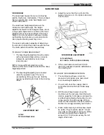
7. Recheck the brush polish marks to see if the
front and rear match, and are even across
the full length of the brush.
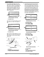
8. The width of the rear brush polish mark can
vary more than the desired 2 to 3 in (50 to
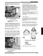
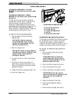
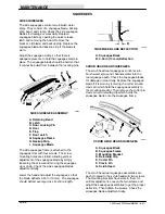
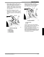
75 mm). There are adjusting knobs located
on the drive side of the scrub head. Turn the
knob clockwise to decrease the width of the
polish mark and counterclockwise to
increase the width of the polish mark. The
polish mark should not exceed 3 in (75 mm).
Use the locking strips to keep the adjusting
knobs in place.
A
B
C
00286
BRUSH ADJUSTMENT KNOBS
A. Locking Strips
B. Front Brush Adjusting Knob
C. Rear Brush Adjusting Knob
9. For maximum brush life, rotate the brushes
from front-to-rear after every 50 hours of
operation.
SCRUB BRUSHES
The scrub brushes are tubular and run the width
of the scrub head sweeping debris into the debris
trough while they scrub the floor. The brushes
should be inspected daily for damage or wear.
Remove any string or wire found tangled on the
scrub brushes, drive or idler hubs.
Rotate the scrub brushes from front-to-rear after
every 50 hours of operation for maximum brush
life and best scrubbing performance.
The scrub brush patterns should be checked
daily. The width of the patterns should be 2 to 3 in
(50 to 75 mm). The scrub brush pattern is
adjusted by turning the adjustment knobs on top
of the scrub head. See
TO ADJUST SCRUB
BRUSH PATTERN
.
TO REPLACE SCRUB BRUSHES
1. Raise scrub head and set scrub head lock.
WARNING: Raised Scrub Head May Fall.
Block Scrub Head Up.
2. Stop engine and set parking brake.
FOR SAFETY: Before Leaving Or
Servicing Machine; Stop On Level
Surface, Set Parking Brake, Turn Off
Machine And Remove Key.
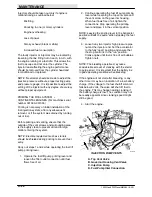
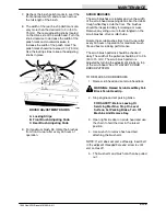
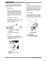
3. Open right side door on scrub head and use
the chain to hold the door in the raised
position.
4. Use wrench to remove hex head bolt
attaching the brush arm.
NOTE: If arm does not come off easily, insert bolt
in the adjacent threaded hole and screw in until
arm comes off.
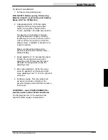
5. The brush arm and brush can then be pulled
out.
Summary of Contents for 1550
Page 16: ...SPECIFICATIONS 1550 Gas LPG Diesel MM283 6 91 1 2 ...
Page 100: ...APPENDIX 1550 Gas LPG Diesel MM283 6 91 4 2 ...
Page 112: ...STANDARD PARTS 1550 Gas LPG Diesel MM283 11 07 6 6 ...
Page 237: ...STANDARD PARTS 6 131 1550 Gas LPG Diesel MM283 3 11 ...
Page 286: ...STANDARD PARTS 1550 Gas LPG Diesel MM283 8 02 6 180 ...
Page 301: ...LPG PARTS 7 15 1550 Gas LPG Diesel MM283 11 07 ...
Page 363: ...DIESEL PARTS 8 53 1550 Gas LPG Diesel MM283 2 05 ...
Page 378: ...DIESEL PARTS 1550 Gas LPG Diesel MM283 2 05 8 68 ...
Page 436: ...BREAKDOWNS 1550 Gas LPG Diesel MM283 8 02 10 38 ...
Page 456: ...CONTINENTAL ENGINE BREAKDOWN GASOLINE LPG 1550 Gas LPG Diesel MM283 2 95 11 20 ...
Page 534: ...PERKINS ENGINE BREAKDOWN DIESEL 1550 Gas LPG Diesel MM283 9 01 15 30 ...
Page 562: ...1011676 CAT ENGINE BREAKDOWN DIESEL 1550 Gas LPG Diesel MM283 2 05 16 28 ...

