MAINTENANCE
3--37
1550 Gas/LPG/Diesel MM283 (9--01)
SCRUB HEAD
SCRUB HEAD
The scrub head houses the two scrub brushes
and the brush drive mechanisms. The scrub head
has two adjustments; scrub head height, and
scrub brush pattern.
The scrub head height adjustment sets the
minimum scrub head height. The height
adjustment should not be changed unless, due to
a major parts replacement or collision, the head
adjustment may have been altered. If the head
height is too low, excessive brush wear, engine
overheating, brush bounce, or excessive brush
drive plug and bearing wear may occur.
The scrub brush pattern adjustment determines
the amount of contact the brush has with the floor.
The brush pattern should be checked daily.
TO ADJUST SCRUB HEAD HEIGHT
1. The head height adjustment must be made
with a full solution tank and tires correctly
inflated; 55 psi (380 kPa) front, 35 psi
(240 kPa) rear.
NOTE: Using a different sized tire on the
machine, other than standard, will affect the head
height adjustment.
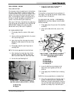
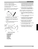
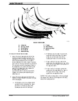
2. The head height adjusting nut is located
under the operator’s seat. The nut is
accessible by lifting up the seat. Hold the
seat up by attaching its chain to the steering
wheel.
B
A
03734
ADJUSTMENT NUT
A. Nut
B. Scrub Head Link
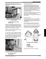
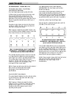
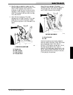
3. Adjust the nut so that the top front of the
head is 13.62 in to 13.75 in (345 to 350 mm)
from the floor.
A
B
B
01822
SCRUB HEAD ADJUSTMENT
A. Scrub Head
B. 13.62 to 13.75 in (345 to 350 mm)
4. If the scrub head is lower than 13.62 in
(345 mm), washers should be added below
the adjusting nut.
TO ADJUST SCRUB BRUSH PATTERN
1. The machine must have correct tire
pressures, full solution tank, and correct
scrub head height adjustment.
2. On a smooth, level floor, apply chalk or
some other material that won’t blow away
easily.
3. With the scrub head raised, move the
machine over the test area. Start the brush
rotation, apply the foot brakes, and lower the
scrubber head, allowing the brushes to spin
in one spot for 15 to 20 seconds. With no
chalk or other material on the floor, allow the
brushes to spin approximately two minutes.
4. Polish marks made by both brushes should
be visible. They should be about 1.5 in (40
mm) wide the full length of the brush. With a
soft brush the polish mark should not
exceed 3 in (75 mm) wide, evenly, the full
length of the brush.
Summary of Contents for 1550
Page 16: ...SPECIFICATIONS 1550 Gas LPG Diesel MM283 6 91 1 2 ...
Page 100: ...APPENDIX 1550 Gas LPG Diesel MM283 6 91 4 2 ...
Page 112: ...STANDARD PARTS 1550 Gas LPG Diesel MM283 11 07 6 6 ...
Page 237: ...STANDARD PARTS 6 131 1550 Gas LPG Diesel MM283 3 11 ...
Page 286: ...STANDARD PARTS 1550 Gas LPG Diesel MM283 8 02 6 180 ...
Page 301: ...LPG PARTS 7 15 1550 Gas LPG Diesel MM283 11 07 ...
Page 363: ...DIESEL PARTS 8 53 1550 Gas LPG Diesel MM283 2 05 ...
Page 378: ...DIESEL PARTS 1550 Gas LPG Diesel MM283 2 05 8 68 ...
Page 436: ...BREAKDOWNS 1550 Gas LPG Diesel MM283 8 02 10 38 ...
Page 456: ...CONTINENTAL ENGINE BREAKDOWN GASOLINE LPG 1550 Gas LPG Diesel MM283 2 95 11 20 ...
Page 534: ...PERKINS ENGINE BREAKDOWN DIESEL 1550 Gas LPG Diesel MM283 9 01 15 30 ...
Page 562: ...1011676 CAT ENGINE BREAKDOWN DIESEL 1550 Gas LPG Diesel MM283 2 05 16 28 ...

