Section 3 ZEPHYR AT A GLANCE
44
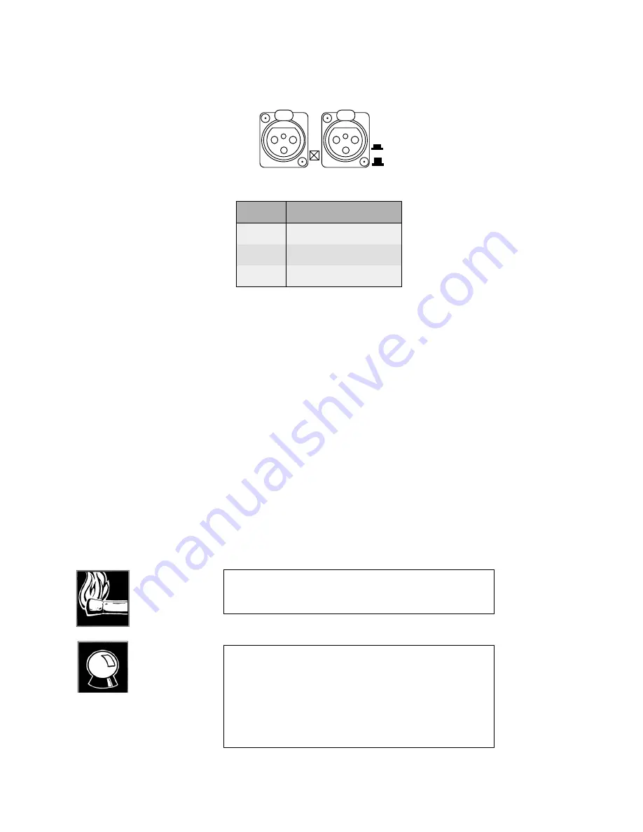
Send (Input) Audio
I N P U T
SEND TO NETWORK
MIC
LINE
A
B
PIN
FUNCTION
1
Ground
2
Audio +
3
Audio -
•
Active balanced.
•
Switch out = LINE: - 15 to +4 dBu nominal level.
•
LINE clip point is +24 dBu.
•
Switch in = MIC: - 68 to - 35 dBu level.
•
Bridging (approximately 100K•) impedance.
The inputs may be sourced from either line or microphone level signals, depending
upon the position of the rear panel switch located near the XLR connectors.
Unbalanced sources may be used by connecting pins 1 & 3 to the source ground while
the signal high is connected to pin 2.
Send gain may be adjusted in the <VOL> volume menu. The send level indicated on the
LCD is the “nominal” operating level. More information about audio levels can be
HOT TIP!
In MONO transmit modes the audio appearing from the “A”
input will be used.
CURIOSITY NOTE!
The Zephyr has the more common pin-outs used for 3 pin XLR
inputs/outputs. You can easily remember the correct signals
when wiring connectors using the phrase “George Washington
Bridge”. Pin 1 = G = Ground, Pin 2 = W = “+” = White (typical
color in mic cable, if there is no white there will be a red
conductor), and Pin 3 = B = “-” = Black (common color in most
audio cables).
Summary of Contents for Zephyr
Page 13: ...Table of Contents 13 SECTION 1 QUICK RESULTS ...
Page 26: ...Section 2 INTRODUCTION 26 This page intentially left blank ...
Page 27: ...Section 2 INTRODUCTION 27 SECTION 2 INTRODUCTION ...
Page 38: ...Section 2 INTRODUCTION 38 This page intentionally left blank ...
Page 39: ...39 SECTION 3 ZEPHYR AT A GLANCE ...
Page 52: ...Section 4 INSTALLATION BASIC OPERATION 52 This page intentionally left blank ...
Page 53: ...Section 4 INSTALLATION BASIC OP 53 SECTION 4 INSTALLATION BASIC OPERATION ...
Page 84: ...Section 4 INSTALLATION BASIC OPERATION 84 ...
Page 85: ...Section 5 ISDN 85 SECTION 5 ISDN ...
Page 105: ...Section 6 NON ISDN NETWORKS 105 SECTION 7 AUDIO CODING ...
Page 118: ...Section 7 AUDIO CODING PRINCIPLES 118 This page intentionally left blank ...
Page 119: ...Section 8 DETAILED MENU REFERENCE 119 SECTION 8 DETAILED MENU REFERENCE ...
Page 157: ...Section 9 REMOTE CONTROL 157 SECTION 9 REMOTE CONTROL ...
Page 176: ...Section 9 REMOTE CONTROL 176 This page intentionally left blank ...
Page 177: ...Section 10 ADVANCED PROBLEM SOLVING 177 SECTION 10 ADVANCED PROBLEM SOLVING ...
Page 196: ...Section 10 ADVANCED PROBLEM SOLVING 196 This page intentionally left blank ...
Page 197: ...Section 11 TECHNICAL INFORMATION 197 SECTION 11 DETAILED TECHNICAL INFORMATION ...
Page 219: ...Section 12 SCHEMATICS 219 SECTION 12 SCHEMATICS ...
Page 221: ...Section 13 MANUFACTURER S DATA SHEETS 221 SECTION 13 MANUFACTURER S DATA SHEETS ...
Page 223: ...Section 14 SPECIFICATIONS WARRANTY 223 SECTION 14 SPECIFICATIONS AND WARRANTY ...
Page 228: ...228 This page intentionally left blank ...
Page 229: ...Section 15 APPENDICES 229 SECTION 15 APPENDICES ...


