background image


S50 Hardware User Guide


1VV0301505  Rev. 3  

Page 44 of 60 

2021-05-05 

Not Subject to NDA 

9.


COMPLIANCES 

The  S50/AI  and  S50/AP  have  been  tested  to  fully  comply  with  the 
appropriate EU, FCC, and IC directives. 

CE testing is intended for end products only. Therefore, CE testing is not mandatory for a 
Bluetooth  module  sold  to  an  OEM  end  product.  However,  Telit  provides  CE  tested 
modules  for  customers  to  ease  CE  compliance  assessment  of  end  products  and  to 
minimize test effort. 

OEM  end product  compliance  assessment  must  be  done for  every end  product by  the 

OEM’s  certification  manager.  It  should  be  noted  that  compliance  assessment  doesn’t 

necessarily mean re-testing in the test lab. Telit test reports are available on request and 
can be used to drastically reduce the test plan and compliance testing costs. 


Note/Tip: All certifications and declarations, except RoHS and ReacH, 
are  only  valid  for  the  S50  running  with  Telit  FW.  If  the 
FLASH  is  erased  and  a  customer  specific  FW  is  loaded  all 
certifications must be re-evaluated or renewed. 


Note/Tip: All measurements and certifications have been done for the 
S50/AI  with internal  ceramic  antenna  and  with a  specific 
external antenna for the S50/AP, which offers the RF signal 
on  a  module  pin.  For  the  S50/AP  the  RED;  FCC  and  IC 
certifications  stay  valid  if  the  OEM  design  follows  exactly  the 
standalone  test  board  trace  design  and  uses  exactly  the  same 
antenna given in chapter 7.5 OEM Layout and Antenna Selection in 
Respect to RED/FCC/IC Certification. 

If this trace design is not the same or this specific antenna is not used 
the following actions should be done. 


RED  Re-assess RED compliance 


FCC  Class II Permissive Change 


IC  Class II Permissive Change 

9.1.


Declaration of Conformity CE 

The  S50/AI  and  the  S50/AP  do  fully  comply  with  the  essential 
requirements of the following EU directives: 


RED 2014/53/EU  

Summary of Contents for BlueMod+S50

Page 1: ...BlueMod S50 HW User Guide 1VV0301505 Rev 3 2021 05 05 Telit Technical Documentation...

Page 2: ...BlueMod S50 Hardware User Guide 1VV0301505 Rev 3 Page 2 of 60 2021 05 05 Not Subject to NDA APPLICABILITY TABLE PRODUCTS BLUEMOD S50 AI CEN BLUEMOD S50 AP CEN...

Page 3: ...ary 10 3 2 Applications 11 3 2 1 General Cable Replacement 11 3 2 2 Industry 11 3 2 3 POS Advertising 11 3 2 4 Healthcare and Medical 11 3 2 5 Sports and Fitness 11 3 2 6 Entertainment 12 3 3 Block Di...

Page 4: ...ODULE PINS 27 5 1 Pin Numbering 27 5 2 Pin Description 28 5 3 Firmware depend Functions 29 5 4 Handling of Unused Signals 29 6 ELECTRICAL CHARACTERISTICS 31 6 1 Absolute Maximum Ratings 31 6 2 Operati...

Page 5: ...2 1 FCC Grant 45 9 2 2 FCC Statement 45 9 2 3 FCC Caution 45 9 2 4 FCC Warning 45 9 2 5 FCC RF exposure Statement 46 9 2 6 FCC Labeling Requirements for the End Product 46 9 3 IC Compliance 46 9 3 1...

Page 6: ...54 12 1 Copyrights and Other Notices 54 12 1 1 Copyrights 54 12 1 2 Computer Software Copyrights 54 12 2 Usage and Disclosure Restrictions 55 12 2 1 License Agreements 55 12 2 2 Copyrighted Materials...

Page 7: ...m integrators about to implement Bluetooth modules in their application 1 3 Contact Information Support For general contact technical support services technical questions and report of documentation e...

Page 8: ...Electro static Discharge Notifies the user to take proper grounding precautions before handling the product Table 1 Symbol Conventions All dates are in ISO 8601 format that is YYYY MM DD 1 5 Related...

Page 9: ...ware versions BlueMod S50 AI with integrated Bluetooth antenna BlueMod S50 AP without integrated Bluetooth antenna and with a 50 rf connection on pin Note Tip The integration of the BlueMod S50 Blueto...

Page 10: ...Hz LGA Surface Mount type BlueMod S50 17 x 10 x 2 6 mm3 Pin compatible to Telit BlueMod family S S42 S42M and SR Flexible Power Management NFC peripheral communication signal interface type A with 106...

Page 11: ...droid as well as implemented in Telit s dual mode module BlueMod SR 3 2 2 Industry BlueMod S50 can be used to monitor and control motors actuators values and entire processes 3 2 3 POS Advertising Blu...

Page 12: ...roller and wireless mouse keyboard applications 3 3 Block Diagram nRF52832 VSUP BlueMod S50 AI RESET I2C UART SPI 1 2 up to 7 3 GND 3 0V 32MHz opt 32kHz Serial Wire Debug onboard antenna 2 GPIO up to...

Page 13: ...ermore it is recommended to place a capacitor in parallel to the CR2032 3V coin cell battery to prolong battery lifetime by compensating the effects of the rising source resistance of the battery to p...

Page 14: ...ontrollable back feeding issues Due to the ultra low power design a few Amps are enough to raise VSUP to an undefined state which may cause a hang up deadlock if power is switched on again Any I O pin...

Page 15: ...al pull up resistor RPU 11k 16k EXT RES may be left open if not used BlueMod S50 E 6 F 6 VSUP GND 3V3 EXT RES B 1 Reset Switch is optional Please Note EXT RES of BlueMod S50 has approx 13k internal pu...

Page 16: ...he UICP protocol refer to 2 Electrical interfacing is at CMOS levels defined by VSUP see chapter 0 Transmission speeds are 9600 921600 bps and 1Mbps asynchronous Character representation 8 Bit no pari...

Page 17: ...y fast a four wire scheme may be successful Connect the serial lines UART RXD UART TXD as well as UART RTS and GND leave UART CTS open The host is required to stop sending data within a short time aft...

Page 18: ...Host RTS CTS RTS IUR_OUT IUR_IN IUR_OUT DTS IUR_IN DTR Figure 7 BlueMod S50 Serial Interface Supporting UICP If I O line availability at the host side is extremely tight 2 I O lines could be saved by...

Page 19: ...en CMOS input oscillation If UICP is deactivated the pull down resistor on UART CTS helps to keep the serial interface active if UART CTS is open If UICP is active and the serial interface is down UAR...

Page 20: ...O pins shall be left unconnected to stay compatible There may be functions assigned to some in future versions of the firmware Refer to 5 3 4 5 I2 C Interface Functionality is defined project specific...

Page 21: ...SO D 1 F 2 SCK SPI_CLK SDI MOSI SDO MISO typical signals Figure 12 BlueMod S50 SPI Interface Example Master Mode 4 7 Serial Wire Debug Interface The Serial Wire Debug SWD interface signals SWDIO SWCLK...

Page 22: ...STMODE UART RXD UART TXD UART RTS UART CTS GND These pins shall be routed to some test pads on an outer layer but can be left open during normal operation when not used Warning Please note the UART is...

Page 23: ...D should be used to tune the resonance of the antenna circuit to 13 56 MHz NFCANT1 BlueMod S50 A 3 NFCANT2 A 4 Ctune1 Ctune2 Cp1 Cp2 Cint2 Cint1 NFC Antenna Figure 13 BlueMod S50 NFC Antenna Tuning 2...

Page 24: ...C1 C2 value depends on CL of crystal and layout Table 5 32 768kHz Crystal Oscillator The module s firmware will detect the presence of a slow clock during the boot process and switch behavior appropri...

Page 25: ...ignal conversion is splitted into 2 phases sample and convert In the sampling phase the capacitor CSAMPLE is charges to the analog source voltage for tACQ by closing the TACQ switch for the acquisitio...

Page 26: ...BlueMod S50 Hardware User Guide 1VV0301505 Rev 3 Page 26 of 60 2021 05 05 Not Subject to NDA TACQ s Max resistance VSOURCE k 10 100 15 200 20 400 40 800 Table 6 TACQ versus R VSOURCE max...

Page 27: ...of 60 2021 05 05 Not Subject to NDA 5 MODULE PINS 5 1 Pin Numbering F1 E1 D1 C1 B1 A1 A2 A3 A4 A5 A6 A7 A8 F2 E2 D2 C2 B2 F3 E3 D3 C3 B3 F4 E4 D4 C4 B4 F5 E5 D5 C5 B5 F6 E6 D6 C6 B6 F7 E7 D7 C7 B7 F8...

Page 28: ...erial Data OUT D2 UART RXD I P0 11 P0 13 Serial Data IN D7 UART RTS O PU L P0 07 Flow Control IUC internally connected to a 470k pull up F3 UART CTS I PD 4 L P0 12 Flow Control IUC B4 IUR OUT O PP 4 L...

Page 29: ...GPIO 10 DIS none GPIO 11 DIS none GPIO 12 DIS none GPIO 13 DIS none GPIO 14 DIS none 1 I Input O Output I O bidir PU pull up PD pull down DIS disconnected PP push pull Table 8 Firmware depend GPIO fu...

Page 30: ...ESTMODE Leave open 1 unused GPIOs Leave open SWDIO SWCLK Leave open Only needed for debug purposes 1 Signals must be accessible for regulatory approving 2 It is strongly recommended to use hardware fl...

Page 31: ...Typ Max VSUP Supply voltage 0 3 3 6 V VPin Voltage on any pin 0 3 VSUP 0 3 3 6 V PRFin RF input level 10 dBm INFC1 2 NFC antenna pin current 80 mA Tstg Storage temperature range 40 125 C Table 10 Abs...

Page 32: ...High Level Output Current drive std 0 5 mA drive hi 1 5 mA RPU RPD pull up down resistor 11 13 16 k Cl Pad Capacitance 3 0 pF 1 maximal number of pins per package with high drive is 3 Table 12 DC Cha...

Page 33: ...y Advertising Off Radio inactive 11 1 A Standby Advertising 3 channels advertising interval 1 28s 22 1 A Connected connection interval 1 28s 1 15 6 A UICP not active or serial interface up Idle Advert...

Page 34: ...z 1 15 dB F F0 1 MHz 1 15 dB F F0 2 MHz 25 17 dB F F0 2 MHz 25 15 dB F F0 3 MHz 51 27 dB F Fimage 30 9 dB max intermodulation level 36 50 dBm Table 15 RF Performance BLE Receiver 1Msps 6 5 2 BLE Trans...

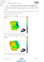
Page 35: ...the recommendations depicted in chapter 7 4 are maintained the following typical antenna radiation patterns can be expected Radiation Pattern will depend on the end products PCB size masses in the an...

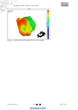
Page 36: ...BlueMod S50 Hardware User Guide 1VV0301505 Rev 3 Page 36 of 60 2021 05 05 Not Subject to NDA Figure 19 Typical Antenna Radiation Pattern at 2480MHz X Y Z...

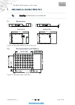
Page 37: ...25 0 25 2 6 0 25 0 25 BlueMod S50 AI 17 0 0 2 0 0 10 0 0 2 0 0 0 8 0 25 0 25 2 6 0 25 0 25 BlueMod S50 AP Figure 20 BlueMod S50 AI an AP Dimensions 7 2 Recommended Land Pattern F1 E1 D1 C1 B1 A1 A2 A...

Page 38: ...eheat Main Heat Peak Tsmax tLmax tpmax Temperature Time Temperature Time Temperature Time C sec C sec C sec 150 100 217 90 260 10 230 50 Average ramp up rate C sec 3 Average ramp down rate C sec 6 Max...

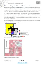
Page 39: ...ment and layout shown in Figure 23 and Figure 24 This is a corner placement meaning the module is placed such that the antenna comes close to the corner of the application PCB red area So the yellow a...

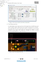
Page 40: ...oosing a trace design suitable for their end product and selecting an antenna according to their needs Only if it is desired to re use the RED FCC and IC certification of the BlueMod S50 AP the follow...

Page 41: ...important to avoid coupling of noise from digital lines to the RF trace and also to avoid RF signal coupling into power supply or analogue lines Therefore the following RF trace design geometry has be...

Page 42: ...ve parts of the BlueMod S50 are to be classified as SELV circuitry OEM s implementing the BlueMod S50 in their products should follow the isolation rules given in regulation EN 62368 1 2014 The PCB ma...

Page 43: ...mple The optional hangup feature to close down the link is provided All other module pins may be left unconnected Host MCU VDD GND 3V3 GPIO o In this example BlueMod S50 AI is connected to an MCU supp...

Page 44: ...clarations except RoHS and ReacH are only valid for the BlueMod S50 running with Telit FW If the FLASH is erased and a customer specific FW is loaded all certifications must be re evaluated or renewed...

Page 45: ...eived including interference that may cause undesired operation 9 2 3 FCC Caution Warning Changes or modifications made to this equipment not expressly approved by Telit may void the FCC authorization...

Page 46: ...er density at 20 cm distance to the human body is well below the limit of 1mW cm2 Note Tip For the BlueMod S50 AI the distance to the human body may be 0cm The same applies for the BlueMod S50 AP if t...

Page 47: ...peration is subject to the following two conditions 1 this device may not cause interference and 2 this device must accept any interference including interference that may cause undesired operation of...

Page 48: ...d 9 3 5 IC Labeling Requirements for the End Product Any end product integrating the BlueMod S50 AI or BlueMod S50 AP must be labeled with at least the following information This device contains trans...

Page 49: ...the Bluetooth SIG rules Bluetooth Declaration Process Document DPD you must complete a Product Listing and Declaration of Compliance DoC referencing the Qualified Design QDID for your product For furt...

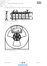
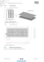
Page 50: ...r as Tape Reel or as tray packing 10 1 Tape Reel Packing The BlueMod S50 modules are packed using carrier tape in this orientation pull off direction from reel 25 empty pockets as leader per packing u...

Page 51: ...0 1 10 9 0 1 0 1 18 3 0 1 0 1 R 0 5 1 75 0 10 0 10 24 0 0 3 0 3 10x4 0 40 0 0 2 0 2 1 5 0 1 0 0 12 0 11 5 0 1 0 1 0 3 3 0 Figure 31 Carrier Tape Dimensions 10 1 2 Reel name p n firmware fw p n trace q...

Page 52: ...52 of 60 2021 05 05 Not Subject to NDA 10 2 Tray Packing 10 2 1 Module Orientation Figure 33 Module Orientation on Tray 10 2 2 Tray Dimensions Figure 34 Tray Dimensions 10 3 Moisture Sensitivity Leve...

Page 53: ...d S50 Hardware User Guide 1VV0301505 Rev 3 Page 53 of 60 2021 05 05 Not Subject to NDA 11 EVALUATION KIT Following evaluation kits are available BLUEEVA S50 AI Please refer to 5 for additional informa...

Page 54: ...ot necessarily mean that Telit intends to announce such Telit products programming or services in your country 12 1 1 Copyrights This instruction manual and the Telit products described herein may inc...

Page 55: ...this document is owned by Telit and its licensors It is furnished by express license agreement only and shall be used exclusively in accordance with the terms of such agreement 12 2 2 Copyrighted Mate...

Page 56: ...OR A PARTICULAR PURPOSE NO THIRD PARTY LICENSORS OF OTHER CODES MUST BE LIABLE FOR ANY DIRECT INDIRECT INCIDENTAL SPECIAL EXEMPLARY OR CONSEQUENTIAL DAMAGES INCLUDING WITHOUT LIMITATION LOST OF PROFIT...

Page 57: ...y the instruction for its use Do not insert or remove the SIM when the product is in power saving mode The system integrator is responsible for the functioning of the final product Therefore the exter...

Page 58: ...ct DTE Data Terminal Equipment ESR Equivalent Series Resistance GPIO General Purpose Input Output I O Input Output MISO Master Input Slave Output MOSI Master Output Slave Input PCB Printed Circuit Boa...

Page 59: ...T HISTORY Revision Date Changes 3 2021 05 05 Updated Table 4 Testmode Boot0 Logic Updated document to new Telit Template standards 2 2018 07 31 Added final power consumption values 1 2018 03 26 FCC an...

Page 60: ......

Reviews: