S50 Hardware User Guide
1VV0301505 Rev. 3
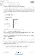
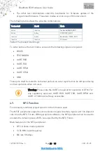
Page 23 of 60
2021-05-05
Not Subject to NDA
•
Wake-on-field low power field detection (SENSE) mode
•
Frame assemble and disassemble for the NFC-A frames
•
Programmable frame timing controller
•
Integrated automatic collision resolution, CRC, and parity functions
4.9.1.
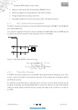
NFCT Antenna Recommendations
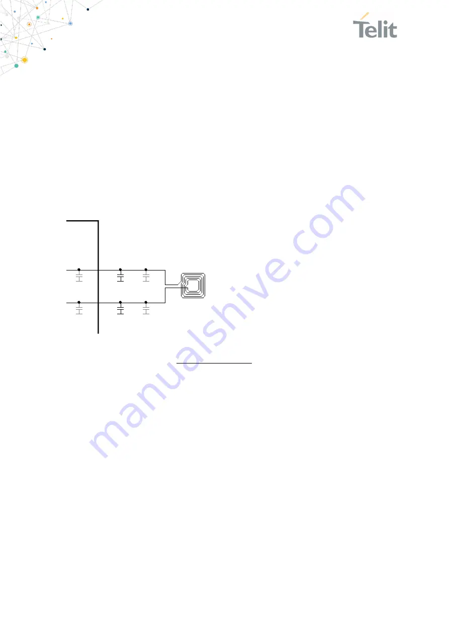
The NFCT antenna coil must be connected differential between NFCANT1 and NFCANT2
pins of S50.
Two external capacitors Ctune1/2 connected between the NFCANTx pins and GND should
be used to tune the resonance of the antenna circuit to 13.56 MHz.
NFCANT1
S50
A-3
NFCANT2
A-4
C
tune1
C
tune2
C
p1
C
p2
C
int2
C
int1
NFC-Antenna
Figure 13: S50 NFC Antenna Tuning
𝐶
𝑡𝑢𝑛𝑒
=
2
(2𝜋 × 13,56𝑀𝐻𝑧)
2
× 𝐿
𝑎𝑛𝑡
− 𝐶
𝑝
− 𝐶
𝑖𝑛𝑡
𝐶
𝑡𝑢𝑛𝑒
= 𝐶
𝑡𝑢𝑛𝑒1
= 𝐶
𝑡𝑢𝑛𝑒2
𝐶
𝑝
= 𝐶
𝑝1
= 𝐶
𝑝2
(𝑎𝑛𝑡𝑒𝑛𝑛𝑎 𝑡𝑟𝑎𝑐𝑘 𝑐𝑎𝑝𝑎𝑐𝑖𝑡𝑎𝑛𝑐𝑒)
𝐶
𝑖𝑛𝑡
= 𝐶
𝑖𝑛𝑡1
= 𝐶
𝑖𝑛𝑡2
= 4𝑝𝐹
4.9.2.
Power Back Feeding
If the NFC antenna is exposed to a strong NFC field, power back feeding may occur. That
means, current may flow in the opposite direction on the supply due to parasitic diodes
and ESD structures.
If a battery is used that does not tolerate return current, a series diode must be placed
between the battery and the S50 to protect the battery. An ultra-low forward
voltage Schottky diode should be chosen to keep the battery life reduction as small as
possible.

