14
en | Maintenance
2020-07 | 01 | F.01U.387.060
Customer Maintenance Manual
Bosch Security Systems, LLC
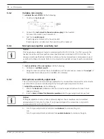
5.3.2
Validate mic circuitry
To
validate the mic PCBA
, do the following:
1.
Construct a
test circuit
.
2.
Connect the
test circuit to the microphone plug
of the headset.
For more information, see Connectors.
3.
Test for an
audio signal
.
If audio signal is detected, the board is valid.
If audio signal is not detected, the board should be replaced.
5.3.3
Microphone/amplifier sensitivity test
Notice!
This headset was designed, tested, and approved to FAA TSO C139a. The TSO requires the
headset meet the minimum performance specifications as defined in RTCA DO-214a. This
document and specifications listed here reference the test procedures and equipment used
as defined in these standards. Refer to the standard for details on how to perform individual
tests.
To
test sensitivity of the microphone
, do the following:
1.
Calibrate an
artificial mouth
.
2.
Using the test circuit from the mic validation and TSO procedures, measure the
output
of
the headset microphone with a true RMS AC voltmeter.
5.3.4
Microphone sensitivity adjustment
The microphone gain has been factory-adjusted to the nominal level required for normal radio
operation. Microphone sensitivity adjusts by turning the gain adjustment control.
To
adjust the microphone
, do the following:
1.
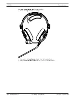
Rotate the
boom mic
clockwise until the microphone gain adjustment access hole is
aligned and open.
2.
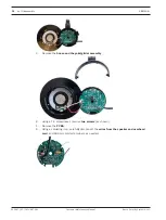
Insert a
2mm x 0.5mm flat-bladed screwdriver
into the gain adjustment access hole.
Notice!
If the gain adjustment access hole is properly aligned, the screwdriver can be inserted
approximately ½-inch into the hole. If not properly aligned, the screwdriver only inserts
approximately 1/8-inch into the hole.
3.
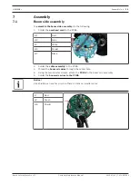
Turn the gain adjustment potentiometer
clockwise
to increase the gain.
OR
Turn the gain adjustment potentiometer
counterclockwise
to decrease the gain.


