


©2022 Televac® - The Fredericks Company | www.televac.com | [email protected] | +1 215 947 2500
mx7b_im rev E Page
16
of
23
8.
Cleaning the MX7B Sensor
8.1
Cleaning Instructions
8.1.1
Remove the cap by unscrewing it (labeled with gray in the diagram).
8.1.2
Pull the anode assembly out of the body (labeled with red in the diagram).
8.1.3
Remove the “O” ring from the body of the sensor, taking care not to scratch the “O” ring seat
(labeled with orange in the diagram).
8.1.4
Wipe off the “O” ring with a lint free wipe.
8.1.5
Visually inspect the “O” ring for cracks or tears, it should also be round and not flattened. If any
physical defects are found, the “O” ring should be replaced.
8.1.6
Blast the vacuum wetted portions of the anode assembly at 30 PSI using 70 to 140 mesh glass
beads (labeled with red and blue in the diagram). Be careful not to damage the glass feedthrough
at the base of the assembly (labeled with green in the diagram). If a rainbow effect is noticed on
the glass feedthrough, a crack may exist and the anode assembly should be replaced. See below
for relevant part numbers.
8.1.7
Blast the vacuum wetted portions of the body with glass beads (labeled with blue in the
diagram), concentrating on the pole piece and “O” ring areas, but making sure to clean all
surfaces wetted to vacuum. If the threaded end of the tube needs to be cleaned, it can be bead
blasted as well.
8.1.8
After cleaning, use compressed dry air to remove any residual glass beads or dust from the
sensor.
8.1.9
Ensure that there are no loose metal particles around the pole pieces.
8.1.10
Grease the “O” ring with Apiezon L or M Grease (a vacuum approved grease). The “O” ring
should be shiny, be sure not to apply excess grease.
8.1.11
Install the “O” ring in the body.
8.1.12
Install the anode assembly in the body; observe the keyway location.
8.1.13
Replace the cap and hand tighten it.
8.1.14
Reinstall the sensor on the vacuum chamber.
8.1.15
Allow several hours for the sensor to degas when your system is pumped down to high vacuum.
8.1.16
If properly cleaned and assembled, the sensor is ready for use without re-calibration unless NIST
traceable calibration is required.
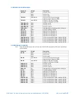
Description
Part Number
MX7B anode assembly
2-7900-707


