User Manual
CXE85X
59300464
Rev.005
9.12.2013
1(44)
CXX Series
Teleste Corporation
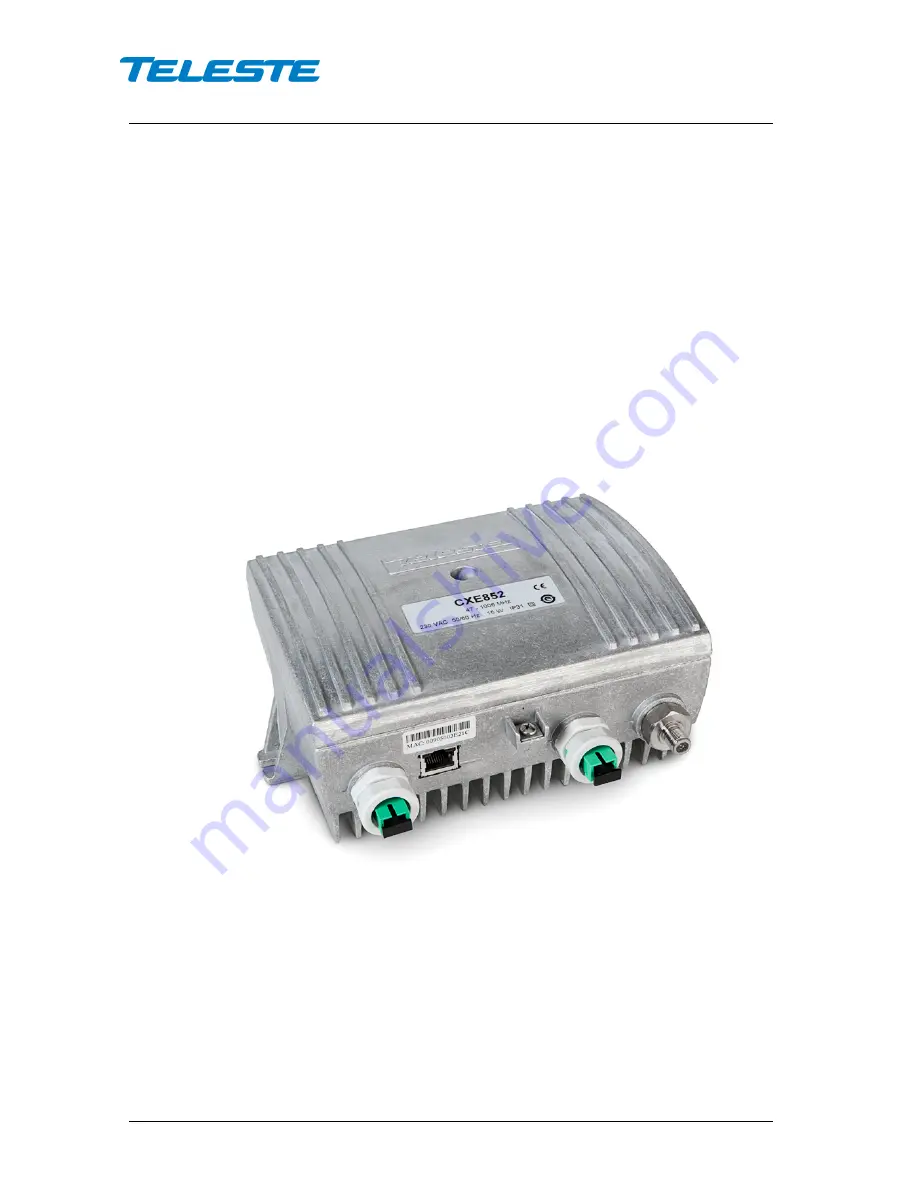
CXE851 / CXE852
Single / Dual optical receiver
with Ethernet management
Page 1: ...User Manual CXE85X 59300464 Rev 005 9 12 2013 1 44 CXX Series User Manual Teleste Corporation CXE851 CXE852 Single Dual optical receiver with Ethernet management...
Page 2: ...agement interfaces 14 Viewer pages SNMP interface 17 Status viewer page 18 Settings viewer page 19 Communication viewer page 21 NTP viewer page 23 Alarm log viewer page 24 Monitoring viewer page 25 Pr...
Page 3: ...l controls that improve reliability Installation can be carried out using basic tools without any software Local or remote configuration using PC software is also possible allowing fine tuning the pro...
Page 4: ...nstalled either into a street cabinet or to a sheltered outdoor environment Note The fibre adapter and the Ethernet port are not waterproof The CXE85x should be installed in a vertical position so tha...
Page 5: ...arate grounding However the amplifier housing has to be grounded from the grounding point The supply voltage fuse is located on the upper right corner of the amplifier beneath the shroud of the power...
Page 6: ...onnector Cleaning fibre connectors For correct optical operation ensure that all optical connectors are cleaned immediately before mating using a suitable optical connector cleaning kit If a cleaning...
Page 7: ...E852 3 Optical power DC voltage test point 1 4 Optical power DC voltage test point 2 CXE852 5 Mid stage attenuator 6 Mid stage attenuator range jumper 7 Slope selection jumper 8 OLC mode jumper 9 Outp...
Page 8: ...tor range Fig 3 4 pos 6 Slope selection Fig 3 4 pos 7 16 31 dB Flat 0 15 dB Middle sloped High sloped OLC mode jumper Fig 3 4 pos 8 External control jumper Fig 3 4 pos 11 OLC ON External control ON OL...
Page 9: ...o restore RF controls to hardware control to reset communication settings back to factory values or to reset all settings back to factory values Button pressed Status LED Action when released 1 s dark...
Page 10: ...ad is unavoidable the use of transient suppression components parallel to the load is required This is critical as a single transient pulse may destroy the output Note If the control signal output fun...
Page 11: ...he fibre using an optical power meter The CXE85x optical input power range is from 7 dBm to 2 dBm 2 Optical Level Control OLC circuitry provides gain control that compensates for changes in input leve...
Page 12: ...r software releases this range is 20 0 dB for 1 st generation devices and 31 0 dB for 2 nd generation devices In OMI based mode the CXE85x calculates the correct gain based on the user specified trans...
Page 13: ...utoIP feature is enabled by default and has essentially the same functionality than in e g Windows PC First the DHCP client tries to connect to a DHCP server to obtain an IP address netmask and gatewa...
Page 14: ...subnet The reset button can be used to restore factory default communication settings if communication to the unit is lost due to e g unknown IP address Management interfaces SNMP communication CXE85...
Page 15: ...n Windows You can do this by opening Windows Command window by typing cmd into the Start menu search In Commander windows type Telnet If you get a Telnet prompt you have Telnet enabled If you get an e...
Page 16: ...ical input power low Optical input power level is below low limit Optical Major Minor Temperature high Internal temperature is above high limit Status Major Minor Temperature low Internal temperature...
Page 17: ...85x viewer pages and the functionality of the unit CXE85x viewer pages in CATVisor Commander and EMS SNMP interface Status Settings Communication NTP Alarm log Monitoring Properties Some viewer pages...
Page 18: ...sured optical input levels are displayed in the Optical receiver frame The background colour of the Input power data field changes to indicate alarms The Input 2 power and Input in use data fields are...
Page 19: ...80 120 dB V values given by the user RF adjustments In Hardware RF adjustment mode these values are read from the hardware in software modes the hardware settings are overridden with these values The...
Page 20: ...alarm limits and sets the alarms to 3 and 6 dB from the current measured value Clicking Use factory limits enables only low minor alarm limit and sets it to 15 dBm Optical input selection CXE852 only...
Page 21: ...s Delay The time to wait before sending an alarm trap once an alarm is detected Interval The minimum time between successive traps Lifetime The time trap stays in the transmit queue if it cannot be se...
Page 22: ...disable trap sending to this address IP address IP address of remote SNMP trap receiver Port Port number of remote SNMP trap receiver listening to incoming SNMP traps Default port is 162 Community SNM...
Page 23: ...referring to NTP server Current time Displays CXE85x s current time Use the Synchronize now button if you want to synchronize the device s date and time with those of NTP server Set time If NTP server...
Page 24: ...ue red for major alarm yellow for minor alarm The total number of entries in the alarm log list is shown in the Number of entries field The index number of the last entry is displayed in the accompany...
Page 25: ...he frame with following information in the list Analog parameter Name of the monitored parameter Alarm Alarm status of the parameter No HIHI HI LO LOLO Value Current measured value HIHI High major ala...
Page 26: ...ored discrete parameter of the unit is displayed in the lower half of the frame with following information in the list Discrete parameter Name of the monitored parameter Alarm Alarm status of the para...
Page 27: ...delay timers The time delay feature can be used to eliminate false alarm triggering due to momentary disturbances An alarm is only active when Detection is enabled and the monitored parameter has bee...
Page 28: ...t field All these fields can contain up to 63 characters Geographical coordinates of the unit can be entered into respective latitude and longitude fields Station The station type hardware version ser...
Page 29: ...ar to the CATVisor viewer More dedicated info is presented in viewer page chapter Only different and extra page is Maintenance for software update Home WebUI page Figure 15 CXE852 Home page The Home p...
Page 30: ...eld allows storing up to 100 character message into CXE85x non volatile memory It can be used for example as a reminder for the next service technician Monitoring WebUI page Figure 16 Monitoring page...
Page 31: ...HI HI LO and LOLO It s possible to disable enable each threshold by uncheck check the checkbox associated to the threshold Discrete Each monitored discrete parameter of the unit is displayed in the lo...
Page 32: ...the alarm history for latest 16 events All entries are date and time stamped with the most current entry at the bottom The existing values are overwritten when the maximum number of entries rows has b...
Page 33: ...With DHCP mode the IP address is assigned automatically provided that a DHCP server is installed on the network If CXE85x cannot get an IP address within limited tries it will assign the factory defau...
Page 34: ...nding behaviour can be fine tuned with delay interval and lifetime parameters Enable traps Enables disables sending of SNMP traps By default this option is enabled Delay The time to wait before sendin...
Page 35: ...LESTE COMMON MIB Teleste MIBs are available at Teleste Club Trap receivers IP Address IP address of remote SNMP trap receiver Port Port number of remote SNMP trap receiver listening to incoming SNMP t...
Page 36: ...TP server from which the CXE85x obtains its date and time settings Server enable Enable NTP by selecting the check box Use the Synchronize now button if you want to synchronize the device s date and t...
Page 37: ...tact field All these fields can contain up to 63 characters Geographical coordinates of the unit can be entered into respective latitude and longitude fields Device The model hardware version serial n...
Page 38: ...l of the CXE85x s settings The reset can also be done via the front panel reset button Note that this action may result in loss of communication and the viewer needs to be closed and reopened with the...
Page 39: ...ew software versions for CXE85x optical receivers may be found at Teleste Club The new versions may contain bug fixes enhancements and completely new features For details on each software release see...
Page 40: ...LO 5 CXE851 N A rflevel 4 dBm Lo 4 temperature 43 C Nominal 1 properties Prints units identification data For details take a look for Viewer page Properties Example description TELESTE CXE852 OPTICAL...
Page 41: ...al2 hihi 20 hi 10 lo 70 lolo 80 deadband 5 CXE851 N A rflevel hihi 250 hi 200 lo 0 lolo 200 deadband 20 temperature hihi 80 hi 75 lo 10 lolo 20 deadband 2 all Same as info properties rf comm monitorin...
Page 42: ...on off Trap receiver 1 IP address and enable disable trapreceiver2 IPADDR on off Trap receiver 2 IP address and enable disable Monitoring parameters For details take a look for Viewer page Monitoring...
Page 43: ...y special incidental consequential or indirect damages howsoever caused The contents of this document are provided as is Except as required by applicable law no warranties of any kind either express o...
Page 44: ...62 499 144 00 17 http www pitri tv E mail info pitri tv 12 _______________________________________...