78
Service
SeaBat Sonar UI - User Manual
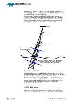
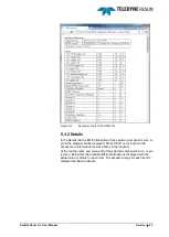
5.2 Diagram
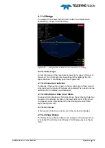
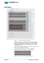
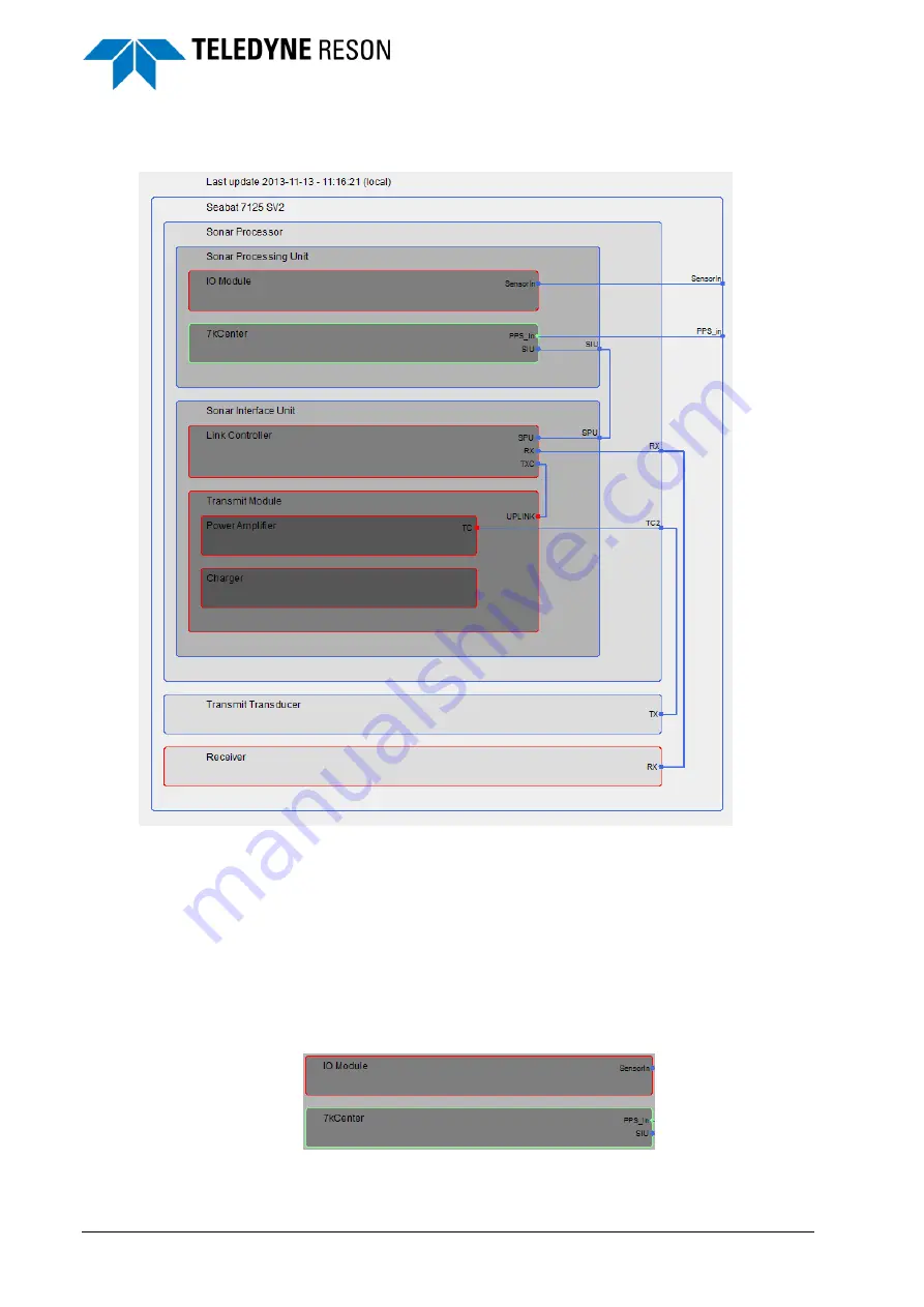
Figure 5-1
Diagram in the Service of a Sonar SV2
When the Service mode is selected in the Sonar UI toolbar a diagram is
displayed. In the diagram the operator can see directly if the complete
sonar system is working fine. All components, wires, and pins should be
in blue or green. BITE information is available for the green (and red)
components and pins.
Click on the item in the diagram to display the available information on the
right side on the Details tab (see page 81).
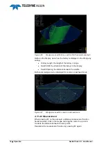
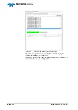
A green component or pin will turn red, if an error is detected.
A green component will turn orange, if a warning is detected.
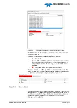
Figure 5-2
Module in error (red), 7KCenter correct (green)

