SeaBat Sonar UI - User Manual
Operation
63
steering and the angle of the detected pipe in PDS2000 is more than the
Steering difference
.
When more pipes or pipe parts are detected the Sonar UI will take an
average of the pipe (parts) positions to calculate a steering angle. The
pipe with the best quality of detections will have a bigger weight in the
average calculation. With this situation it is possible that the steering is
not always on the main pipe which has to be tracked.
When horizontal steering is selected the Sonar UI will change the horizon
steering in the RESON Sonar 7k sonar when the Sonar UI calculates that
it is needed.
The Flex mode has to be
selected in the RESON
Sonar 7k, before the flex
steering can work.
When flex steering is selected the Sonar UI will change the angle of the
center beam of the flex mode in the RESON Sonar 7k sonar when the
Sonar UI calculates that it is needed. The width of the flex mode and the
settings of the flex mode will not be changed.
4.10.6 Five Points Environment
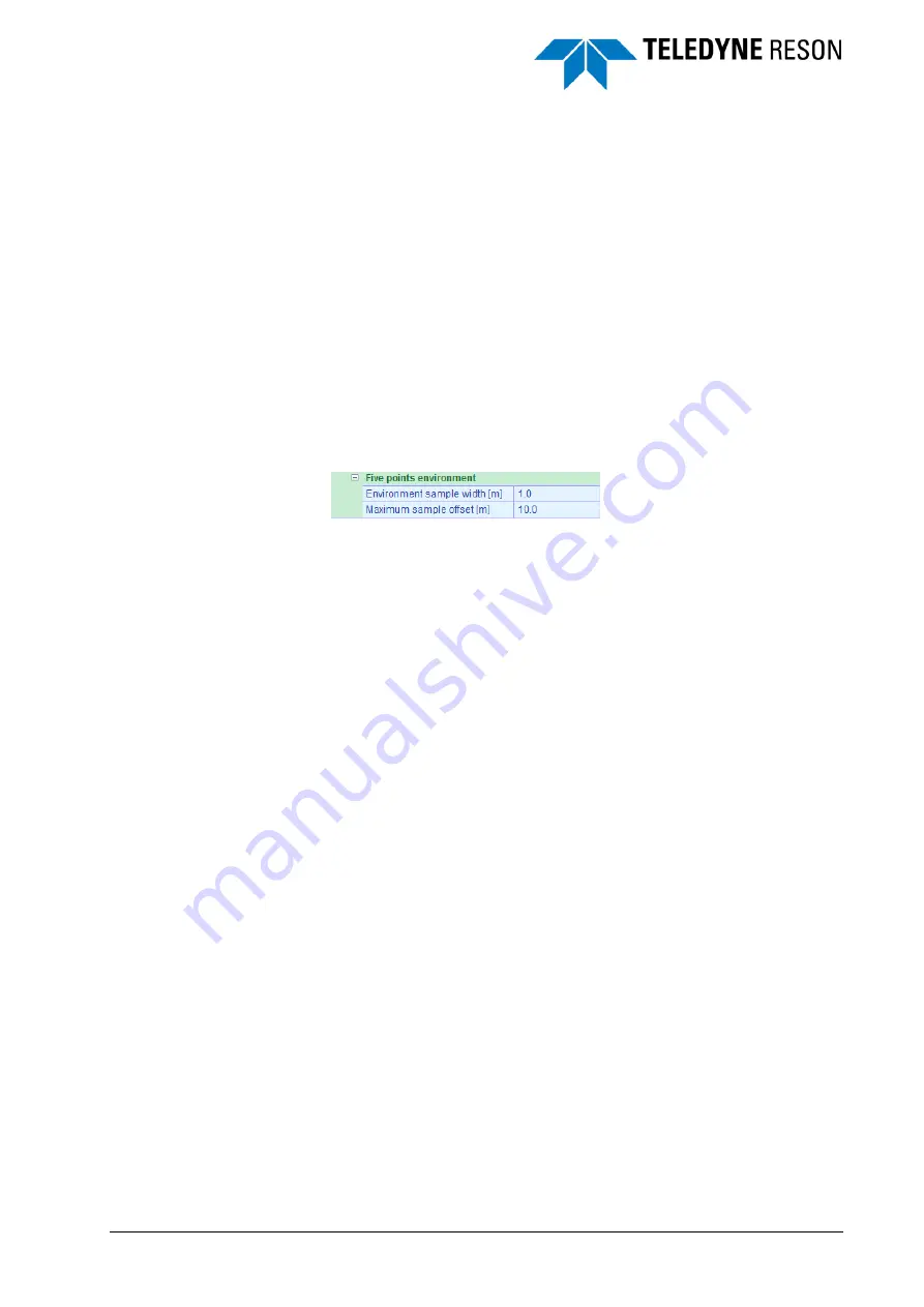
Figure 4-79
Five points environment settings
When the pipe is detected 5 point on and around the pipe will be
computed and outputted to generate a basic profile of the seafloor with
the pipe.
The five points are the top of pipe, the seafloor on both sides of the pipe
(as close as possible to the pipe) and the seafloor on both sides further
away from the pipe (maximum sample offset). The five point information is
output on each segment length. See section 4.10.3.1.
4.10.6.1 Environment sample width
This is a window over the multibeam data in which an average is
computed for the seafloor detections.
4.10.6.2 Maximum sample offset
This is the distance from the top of the pipe to the seafloor detection
away from the pipe.
4.10.7 Pipe Detection Considerations
Follow the sequence of the pane:
1. Enable in the display pane the correct pipe layer settings.
2. Set the pipe in sway parameters to have good detections. Set pipe
gating to improve the detections.
3. Set the pipe parts creation parameters to create pipe parts. The pipe
parts are created from the detections as set in step 1.
4. Set the parameters for the pipe route creation. The pipe route is
created from the pipe parts as set in step 2.
5. Set the pipe segment length to define the number of output points.
For each set segment length one output point. (May be different in
corners or end of pipe routes)

