background image

THCD-401 Instruction Manual


Page 45 of 47 


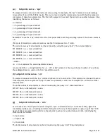
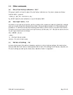
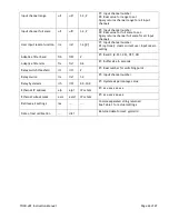
Appendix B - Factory Defaults 

Setting  

Default Value   Additional Information 

Repeat Rate (for output readings) 

Repeat off 

Ethernet IP Address 

192.168.1.180 


Ethernet Subnet Mask 

255.255.255.0 


Input Channel Label (for all channels) 

“ChX ” 

 X = input channel number (1 to 4) 

Input Channel Show Flag (for all channels) 


Input Channel Units String (for all channels)  “”  

No units strings set 

Input Channel Range (for all channels) 

10.000 

Sets display precision to 3 decimal 

places 

Input Channel Full Scale (for all channels) 

10.0 


Input Channel User Rezero (for all channels)  0.0 

No rezero set 

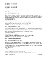
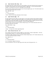
Setpoint Source (for all setpoints) 

Internal source 

Setpoint Initial Value (for all setpoints) 

0.0 


Setpoint Initial Mode (for all setpoints) 

Close mode 

Date of Last Factory Calibration 

10101 


Adaptive Filter Band 

0.2% 


Adaptive Filter Buffer Size 

2 seconds 

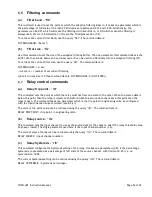
Relay Trip Point 

10.0 


Relay Source Channel 

Input channel 1 

Relay Hysteresis 

2.0% 


Summary of Contents for THCD-401

Page 1: ...INSTRUCTION MANUAL THCD 401 I S O 9 0 0 1 C E R T I F I E D www teledyne hi com ...

Page 2: ...which if not avoided could result in death or serious injury Do not proceed beyond a WARNING notice until the indicated conditions are fully understood CAUTION indicates a hazardous situation which if not avoided could result in minor or moderate injury Do not proceed beyond a CAUTION notice until the indicated conditions are fully understood and met NOTICE calls attention to a procedure or practi...

Page 3: ...FACE SOCKET PINOUT MINIATURE 15 PIN D TYPE 11 USB CONNECTOR USB TYPE C 11 WARNINGS 12 4 FRONT PANEL OPERATION 13 INTRODUCTION 13 COMMON SWITCH FUNCTIONS 13 a Menu screens 13 b Editable screens 13 c Edit mode 13 HMI BREAKDOWN 14 a Main Screen 14 b Main Menu Screen 15 c Inputs Screen 16 d Setpoint Screen 17 e Ethernet Screen 18 f Filtering Screen 19 g Relay screen 20 h Factory Defaults Confirm Scree...

Page 4: ...al value siv 33 g Setpoint initial mode sim 33 COMMS COMMANDS 34 a Ethernet IP address eip 34 b Ethernet subnet mask esm 34 CHANNEL SETUP COMMANDS 34 a Input channel display label dil 34 b Input channel units string uiu 35 c Input channel range uir 35 d Input channel full scale uif 35 FILTERING COMMANDS 36 a Filter band flb 36 b Filter size fls 36 RELAY CONTROL COMMANDS 36 a Relay trip point rlt 3...

Page 5: ...b Setpoint Source 39 USER REZERO 39 ADAPTIVE FILTERING 39 a Operational band 40 b Filter size 40 8 SERVICE AND CALIBRATION 41 SERVICE 41 CALIBRATION 41 ADJUSTMENT 41 CLEANING 41 END OF LIFE 41 WARRANTY POLICY 41 RETURN POLICY 42 9 APPENDICIES 43 APPENDIX A THCD 401 COMMAND SET SUMMARY 43 APPENDIX B FACTORY DEFAULTS 45 APPENDIX C SETTINGS IN RAS COMMAND STRING 46 ...

Page 6: ...n relevant units Any engineering units can be accommodated with a free text input The display also allows for an easy to use menu structure for configuration Interfaces to the THCD 401 include Ethernet RS232 via USB or it can be used with just analog signals NOTICE The instruments described in this manual may be available with multiple pin outs Ensure that all electrical connections are correct NO...

Page 7: ... 12PCF XXX AM Custom length cable circular IP67 to THCD Pinout H 65 576 AF 4 AM 4 Ft Cable Pinout H 65 149 AF 8 AM 8 Ft Cable Pinout H 65 148 AF 25 AM 25 Ft Cable Pinout H 65 160 AF 50 AM 50 Ft Cable Pinout H 65 193 AF 100 AM 100 Ft Cable Pinout H 65 576 Special AF XXX AM Custom Length Cable Pinout H 65 791 AF 8 AMU 8 Ft Cable Black Connector H pinout THCD to U pinout MFC 65 791 99 AF XX AMU Custo...

Page 8: ...arm up Time to Full Accuracy 20 minutes assumes unit already stabilized at ambient and excludes transducer warm up time Measurement and Output Power Supply Out 15 VDC 300 mA max channel 24 VDC 350 mA max channel Total transducer load not to exceed 40W DC Input Signal 10 Volt 10 8 Volt guaranteed or 4 20 mA 3 21 mA guaranteed factory option 16 bit ADC Impedance 1 MΩ Voltage input Error 0 02 of read...

Page 9: ...9999 6 characters decimal point counts as character Transducer connectors 4 15 pin D type female on THCD 401 Serial USB C USB 2 0 over USB C connector Ethernet TCP IP Configurable static IP address and subnet mask Single host stack 100 Base T Mechanical Housing Dimensions 3 23 H x 6 65 W x 8 14 D 82mm x 169mm x 206mm Weight 1 85 kg Panel cut out 2U x 19 Rack ...

Page 10: ...ions The instrument is designed to be rack mounted Note that the instrument must always be situated in such a way as to enable adequate air circulation about the unit If a transducer was supplied with the THCD 401 a suitable cable may have been included NOTICE The controller should be installed in a clean and careful manner Take care not to drop the product and avoid impacts to prevent damage Tran...

Page 11: ...xt Setpoint 2 10 0v Signal Ground 11 TTL Input Disable Menu 12 TTL Input Disable Zero 13 Relay Com 14 Relay NO 15 Relay NC Not Yet implemented USB Connector USB Type C The connector supports USB C 2 0 cables without the SuperSpeed pairs Therefore connecting a fully featured USB C 3 1 cable will not provide SuperSpeed functionality although the cable will still work as per the USB 2 0 specification...

Page 12: ...NG Instrument must always be grounded earthed Failure to heed this warning could result in serious personal injury and or damage to the equipment WARNING Instrument must not be used when faulty wet or near water Failure to heed this warning could result in serious personal injury and or damage to the equipment WARNING The THCD 401 is intended for use in non condensing environments only Condensate ...

Page 13: ...ain screen The Enter switch actions the chosen menu selection to an editable or information screen see HMI breakdown for more details b Editable screens On any screen that has editable fields the scroll wheel will move the selection between the possible editable fields Func goes back to the parent screen which is usually the menu that was used to get to the screen in question Enter activates edit ...

Page 14: ...abel When a channel is selected its associated label is highlighted as shown above on channel 4 This selection is cleared automatically when a valid function is selected e g setpoint mode change or after 5 seconds have passed if no function is selected If a setpoint value is being changed the channel selected splits into two lines the bottom showing the input data and the top showing the setpoint ...

Page 15: ...n Menu screen provides access to the configuration sections of the THCD 401 Switch Functions Func Go back to Main screen No function No function Wheel Move menu selection up and down Ch1 to Ch4 No function Open Auto Close No function Enter Go to selected menu item page ...

Page 16: ...s and change the channels input range and full scale voltage see the Principles section 7 2 for more information on this The number of decimal places selected on the range field dictates the number of decimal places shown for the input data for the channel on the Main screen To reduce the number of decimal places change the number under the edit cursor to a decimal point and the system will auto f...

Page 17: ...hing else From this screen the initial settings that can be configured are the setpoint value anything between 0 and full scale and setpoint mode AUTO OPEN CLOSE The source of a setpoint can also be changed cycling between INT SLV1 SLV2 SLV3 SLV4 For more information on setpoints see the Principles section 7 4 Switch Functions Func Go back to Main Menu screen in normal operation Undo changes in ed...

Page 18: ...er can be cycled to during edit mode the THCD 401 will cap at 255 Switch Functions Func Go back to Main Menu screen in normal operation Undo changes in edit mode Move edit cursor left in edit mode Move edit cursor right in edit mode Wheel Move edit field selection in normal operation Change char under cursor in edit mode Ch1 to Ch4 No function Open Auto Close No function Enter Go to edit mode for ...

Page 19: ... allows settings between 0 and 6 seconds of filtering For more information on the adaptive filter see the Principles section 7 6 Switch Functions Func Go back to Main Menu screen in normal operation Undo changes in edit mode Move edit cursor left in edit mode Move edit cursor right in edit mode Wheel Move edit field selection in normal operation Change char under cursor in edit mode Ch1 to Ch4 No ...

Page 20: ...een as well and is represented as a percentage of full scale of the source channel with limits of 0 0 i e no hysteresis to 10 0 Switch Functions Func Go back to Main Menu screen in normal operation Undo changes in edit mode Move edit cursor left in edit mode Move edit cursor right in edit mode Wheel Move edit field selection in normal operation Change char under cursor in edit mode Ch1 to Ch4 No f...

Page 21: ...tra user interaction check before performing the default If actioned all settings are returned to their factory defaults see Table 2 in Appendix B Once completed a message appears on screen to tell the user to restart the device this is necessary to apply the defaults Switch Functions Func Go back to Main Menu screen Close Confirm factory default function All other switches No function ...

Page 22: ...rectly entered When a pin is incorrectly entered a message will display as shown below Switch Functions Func Go back to Main Menu screen in normal operation Undo changes in edit mode Move edit cursor left in edit mode Move edit cursor right in edit mode Wheel Move edit field selection in normal operation Change char under cursor in edit mode Ch1 to Ch4 No function Open Auto Close No function Enter...

Page 23: ... screen provides access to the factory settings and the menu lockout configuration screen Switch Functions Func Go back to Main screen No function No function Wheel Move menu selection up and down Ch1 to Ch4 No function Open Auto Close No function Enter Go to selected menu item page ...

Page 24: ...essed or clear the pin so that no pin is required to access the THCD 401 main menu Switch Functions Func Go back to Main Menu screen in normal operation Undo changes in edit mode Move edit cursor left in edit mode Move edit cursor right in edit mode Wheel Move edit field selection in normal operation Change char under cursor in edit mode Ch1 to Ch4 No function Open Auto Close Clears the menu locko...

Page 25: ...aspects of the device Main screen The main screen is the first page the user will see upon opening the webserver Along the top the tabs are always visible and allows the user to navigate between pages The sidebar is also always visible allowing the user to start and stop streaming and control streaming settings it is also possible to rezero all channels and control setpoints on all channels Note f...

Page 26: ...low is the channel configuration for just one channel When the user navigates to the channel configuration page there are 4 of these sections in a column so that user can change the settings for each channel Units string allows for 7 characters so that the user can note what units are being measured Range is the Engineering units range of the device The number of decimal places set for the range d...

Page 27: ...f a Communication section The communication section allows the user to change the device IP Address and Subnet mask To apply a settings change from this page the device must be reset the device will start this process automatically and on the webserver a message will popup telling the user to wait 10 seconds then go to new address Note clicking Ok will take the user to the new address ...

Page 28: ...is filtered over a time greater than 5 will turn the filtering band to on automatically For more information on how the adaptive filter works see the Principles section 7 6 c Relay Page The relays page allows the user to control when the relay will trigger The Source is the channel on which the relay trip point is checked against The Hysteresis is a window around the trip point at which the relays...

Page 29: ...r The user can store up to 11 points The Links at the top of the page allow the user to switch between each channel s linearization data Once all required points are entered Apply should be clicked Because the device will need to be reset to build the new linearization tables the device will check with the user to ensure this is what they wish to do If the User clicks Yes then the webpage will sho...

Page 30: ...ated by commas if more than one The first letter to be entered on the command line before any command or query is the address identifier The is a legacy character left in to provide some level of backwards compatibility and familiarity with Chell s remote comms protocol from earlier display models It can no longer be configured and is now fixed to the character a On TCP IP this address doesn t rea...

Page 31: ...at only data for channels that are marked as being shown is output see the dis command Error Reference source not found later If the input voltage for a channel is more than 15 over the full scale voltage set for the channel the reading below will be replaced with the over range error RANGE The readings output format is in CSV format with the channel data comma separated on one line followed by a ...

Page 32: ...ded that when 100ms repeated output is used the data will be taken every 100ms and buffered up to be sent out every 500ms in blocks of 5 readings This has proven to be a more robust output method For consistency the output from serial comms also works in the same way c Setpoint value spv This command is used to set the value of a particular setpoint The command takes two parameters the first is th...

Page 33: ...ame as the second parameter above source identifier string identifier for x INT or SLVn where n is the input channel number You will see these designations are used on the front panel HMI as well f Setpoint initial value siv The setpoint value set with the spv command above is not non volatile This command can be used to set an initial setpoint value on system startup It takes two parameters which...

Page 34: ...sk used as part of the TCP IP communication As with the IP address the parameter should be entered as a standard 4 octet mask e g 255 255 255 0 Each octet value is again capped if a value greater than 255 is entered Again the THCD will respond and display the following before restarting the system UNIT SHOULD AUTO RESTART IF NOT RESTART TO APPLY CHANGES The current subnet mask can be retrieved usi...

Page 35: ... the second is the actual value for the range The number of decimal places passed in the range value dictates the number of decimal places shown for the main data output up to a max of 4 decimal places any more will get chopped off The current range of all input channels is retrieved using the query uir The data returned is one line for each input channel and is as follows CH x INPUT RANGE range w...

Page 36: ...Relay trip point rlt This command sets the point at which the relay switches from one state to the other When the source data is below this point then the relay is closed so therefore when the source data rises above this point then the relay is open The command takes one parameter which is the trip point in engineering units as configured with the Input Channel range command see 6 5 c The current...

Page 37: ...ut channel number 1 4 The optional second parameter is 0 and this clears any value already generated by a previous rezero for a specific input channel To find the current user rezero values for all input channels use the query irz The data returned is one line for each input channel and is as follows CH x REZERO rezero where x the input channel number rezero the current rezero value c Retrieve all...

Page 38: ... attached to the THCD will have a full scale voltage which is the maximum voltage the device should output under normal operating conditions Typical values are 10V 5V and 1V The full scale is used with the range to determine what the user sees on the screen for any input voltage The THCD will show the over range error RANGE for any channel whose voltage input is more than 15 over the full scale vo...

Page 39: ...ches or via the remote comms Slave source in this case the setpoint uses a percentage of an externally produced value The percentage is set via the switches and the external value comes from one of the other input channels Setpoints are volatile in that when power is removed from the THCD 401 the current setting of each setpoint value and mode is NOT remembered However there are some initial power...

Page 40: ...pe of adaptive filtering can cause readings to be displayed abnormally particularly if the buffer size is one of the larger available settings where the displayed readings seem to jump about as the filter is disabled and then re enabled when the data excursions fall into the pre set band This is because outside of the band the display will show the real unfiltered readings whilst constantly taking...

Page 41: ...ll ensure optimum performance throughout the life of the product Adjustment WARNING The presence of lethal voltages within the instrument means that the user is strictly forbidden from removing the covers There are no user adjustments in the instrument Cleaning A dirty instrument may be wiped clean with a damp cloth then wiped dry immediately WARNING Under no circumstances should the instrument be...

Page 42: ... Information section of the Hastings Instruments website http www teledyne hi com inforeq htm WARNING Contaminated parts can be detrimental to health and environment Ensure instruments are free of hazardous contamination prior to shipment Company contact information TELEDYNE HASTINGS INSTRUMENTS 804 NEWCOMBE AVENUE HAMPTON VIRGINIA 23669 U S A ATTENTION REPAIR DEPARTMENT TELEPHONE 757 723 6531 1 8...

Page 43: ...s mode of all setpoints Setpoint source sps sps 1 4 0 4 P1 Setpoint number P2 0 Internal source 1 4 Ratio source 1 4 Query returns source of all setpoints Setpoint initial value siv siv 1 4 P1 Setpoint number P2 Real value to set Query returns initial value of all setpoints Setpoint initial mode sim sim 1 4 0 2 P1 Setpoint number P2 0 Auto mode 1 Open mode 2 Closed mode Query returns initial mode ...

Page 44: ...ptional clears current user input rezero setting Adaptive filter band flb flb P1 Band 0 01 1 00 OFF ON Adaptive filter size fls fls 0 6 P1 Buffer size in seconds Relay switch threshold rlt rlt P1 Real number for switching point Relay source rls rls 1 4 P1 Input channel number Relay hysteresis rlh rlh 0 0 10 0 P1 Hysteresis percentage value Ethernet IP address eip eip IP octets P1 xxx xxx xxx xxx E...

Page 45: ...g for all channels No units strings set Input Channel Range for all channels 10 000 Sets display precision to 3 decimal places Input Channel Full Scale for all channels 10 0 Input Channel User Rezero for all channels 0 0 No rezero set Setpoint Source for all setpoints 0 Internal source Setpoint Initial Value for all setpoints 0 0 Setpoint Initial Mode for all setpoints 2 Close mode Date of Last Fa...

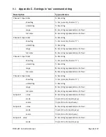
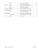
Page 46: ...t label 5 char string show flag 1 char currently fixed at Y units string 7 char string range 8 char string representation of a float full scale 8 char string representation of a float Channel 4 input label 5 char string show flag 1 char currently fixed at Y units string 7 char string range 8 char string representation of a float full scale 8 char string representation of a float Setpoint 1 value 8...

Page 47: ... 2 as for spm query source 1 byte 0 4 as for sps query Last factory calibration date 6 char string format as for dlc query Adaptive filter band 4 char string representation of a float size 1 byte 0 6 as for fls query Relay trip point 8 char string representation of a float hysteresis value 4 char string representation of a float source 1 byte 0 3 ...

Reviews: