


THCD-401 Instruction Manual
Page 39 of 47
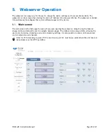
Setpoint Control
As mentioned previously, there are 4 analog voltage outputs for setpoint control. These allow a mass flow
controller to be operated. Each setpoint command output has a voltage full scale that matches its associated
input channel configuration.
Example
If a channel is setup for a 100 slpm 5V full scale device, and the setpoint value is 10.0 (assuming setpoint is in
Auto mode and not a slave source), then the output voltage of the setpoint would be 0.5V.
The setpoints do have some configuration parameters that can be used to alter the function of the setpoint
control, and they are detailed as follows:
(a)
Setpoint Mode
Each setpoint can be configured in one of three modes – Auto, Open and Close.
•
In Auto mode the setpoint output is dependent on the setpoint source and value settings (see below).
•
In Open mode the setpoint outputs a voltage greater than the full scale of the device. For a setpoint
command full scale of 5V or less, the output in this mode is nominally 7V. For any other setpoint
command full scale (e.g. 10V), the output in this mode is nominally 12V.
•
In Close mode the setpoint outputs a voltage less than the minimum output voltage of most devices,
the setpoint output voltage is nominally –0.25V.
(b)
Setpoint Source
The setpoint source dictates where the setpoint value comes from, assuming the mode is set to Auto (see
above). This can be one of two possibilities – Internal or Slave.
•
Internal source – the setpoint uses the value set internally via the ‘
▲
’ & ‘
▼
’ switches or via the
remote comms.
•
Slave source – in this case the setpoint uses a percentage of an externally produced value. The
percentage is set via the ‘
▲
’ & ‘
▼
’ switches and the external value comes from one of the other input
channels.
Setpoints are volatile, in that when power is removed from the THCD-401, the current setting of each setpoint
value and mode is NOT remembered. However, there are some initial power-up settings for the value and
mode of each setpoint channel that can be set via the front panel HMI, webserver or remote comms (see
appropriate sections above, for more information).
User Rezero
Over time it is possible that an input may ‘drift’ slightly due to various conditions (temperature changes, etc.).
As such it may be necessary for the channel to be rezeroed by the user.
The user rezero function is provided for this task. It simply takes the current reading and uses that as an
additional offset for the channel in question, subtracting the value from all subsequent readings. Ensure any
process value to be zeroed, is in fact truly zero before performing this function. This would mean isolating flow
devices or fully pumping a pressure device.
Note that the user rezero via comms or webserver also provides the facility for clearing any user rezero value
that may have already been set. This should be used before any input calibration is performed to ensure that
the calculated calibration points are not distorted by the user zero offset.
Adaptive Filtering
The THCD-401 includes an adaptive averaging filter on the display and comms readings output to aid in
‘smoothing out’ unwanted ‘noise’ on the displayed readings. The filter is not channel specific – if enabled it
filters all readings for all displayed channels.


