Teledyne 202 Series Instruction Manual Download Page 22

200/202 Series Flowmeters and Controllers Instruction Manual


EAR99 Technology Subject to Restrictions Contained on the Cover Page


Page 22 of 27 

CAUSE:

 Plugged orifice. 

ACTION:

 Verify the presence of a 10-50 psig pressure across the instrument. If present, shut off gas 

supply and power supply. Remove orifice per Section 3.7. Examine orifice. If plugged, clean or replace 
as applicable. Reassemble valve. 


SYMPTOM:

 Flow meter reads other than 0.00 VDC with no flow, or there is a small flow when flow 

meter reads 0.00 VDC. 

CAUSE:

 ZERO potentiometer is out of adjustment. 

ACTION:

 Shut off all flow. Adjust ZERO potentiometer until output reads 0.00 VDC. 


SYMPTOM:

 Flow meter out of calibration and nonlinear. 

CAUSE:

 Leaks in gas inlet or outlet fittings. 

ACTION:

 Check all fittings for leaks by placing soap solution on all fittings between gas supply and final 

destination of gas. Check flow meter for leaks. Replace “O” rings

 if required or recalibrate as necessary. 


Adjustments 

The following sections detail adjustments that can be made to a Hastings flow instrument’s calibration.  The 

process of making these adjustments is only recommended if appropriate calibration equipment is available, 
such as the appropriate leak-tight fittings and a formidable flow reference. 

3.3.1. 

Calibration Procedure (controller) 

NOTE: Steps 5 and 6, adjusting the SPAN pot and 
performing a calibration run, will require the use of a 
calibration reference. 


1)


Connect power to the instrument, put in AUTO 
state, and allow 10% flow for 30 minutes as a 
warm-up. 


2)


After the warm-up period, set the flow to zero and 
wait for 2 minutes.  Check to make sure there is 
zero flow. 


3)


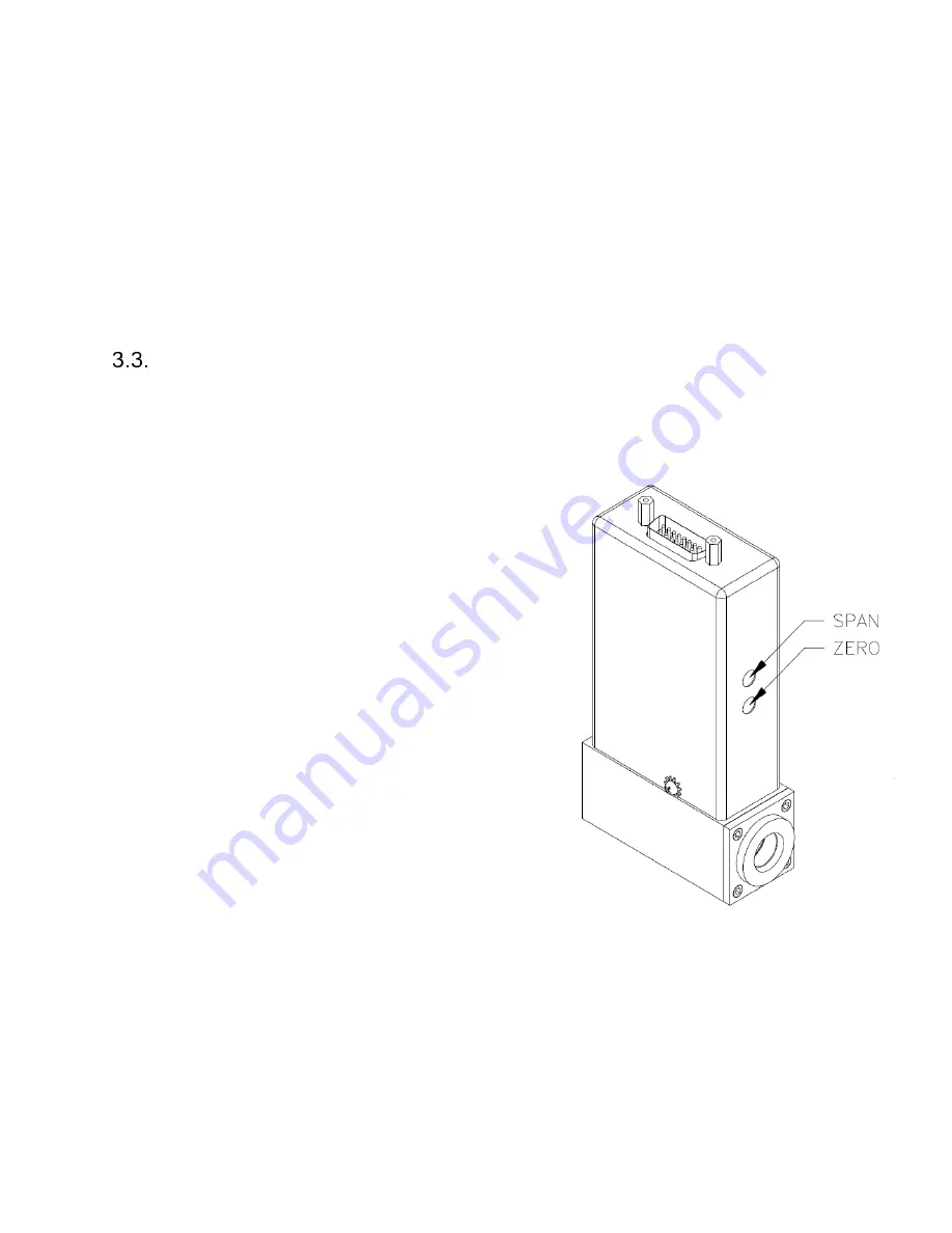
Adjust the ZERO potentiometer (bottom hole on 
inlet side) so that the flow instrument outputs 
0.000 VDC (6,5 on 15V, 2,8 on 24V). 


4)


Override the valve closed or give a 0% flow 
command.  Turn on gas supply to inlet of 
instrument. Adjust the orifice underneath the 
controller to obtain zero flow. 


5)


Set the flow to 100% (don’t forget to put the valve 

state back into AUTO if you closed it in step 4) and 
Ensure that full range flow can still be obtained at 
minimum inlet pressure. 


6)


NOTE 1:

 Controllers regulate flow to the analog command given.  If a user commands 5 volts, the 

controller will move the valve to indicate 5 volts of flow regardless of how the span pot is set.  If 
users keep turning the span pot, the controller will continue to regulate to 5 volts as long as the 
valve can physically pass the flow needed to get there. 

NOTE 2:

 Users need a flow reference in series with the controller to tell exactly what flow rate is 

passing at the controller

s full scale.  Set the command to 100%. Adjust the SPAN potentiometer (top 

hole on inlet side, usually under a sticker) until the flow controller full scale (5.000 VDC) matches the 
desired flow rate indicated by the flow reference. 


7)


Record flow controller and flow reference outputs for flow rates of 20%, 40%, 60%, 80% and 100%.  
Take the data and make sure the output is within ±1% of full scale at each point (accuracy spec). 

Summary of Contents for 202 Series

Page 1: ...ION MANUAL www teledyne hi com I S O 9 0 0 1 C E R T I F I E D Use and Disclosure of Data Information contained herein is classified as EAR99 under the U S Export Administration Regulations Export reexport or diversion contrary to U S law is prohibited ...

Page 2: ... Number 140 102009A October 2009 Revision L Document Number 140 082010 August 2010 Revision M Document Number 140 072011 July 2011 Revision N Document Number 140 072013 July 2013 Revision P Document Number 140 032021 March 2021 Visit www teledyne hi com for WEEE disposal guidance Description of Symbols and Messages used in this manual WARNING indicates a hazardous situation which if not avoided co...

Page 3: ... 4 3 Upstream Differential Pressure 12 2 4 4 Other Mounting Fitting Options Notes 12 2 4 5 Laminar Flow Element LFE Configuration 13 ELECTRICAL CONNECTIONS 14 2 5 1 Bipolar 15 VDC Power Supply to Bipolar Connections 14 2 5 2 Unipolar 24 VDC Power Supply to Unipolar Connections 15 2 5 3 General Connection Notes 15 OPERATION 16 2 6 1 Operating Conditions 16 2 6 2 Zero Check 16 2 6 3 High Pressure Hi...

Page 4: ...ROL 20 3 MAINTENANCE 21 AUTHORIZED MAINTENANCE 21 TROUBLESHOOTING 21 ADJUSTMENTS 22 3 3 1 Calibration Procedure controller 22 3 3 2 Miscellaneous Adjustments 23 ENDCAP REMOVAL 23 PRINTED CIRCUIT BOARD REPLACEMENT 23 SENSOR REPLACEMENT 23 ORIFICE CHANGES 23 3 7 1 HFC 202 Orifice 24 4 WARRANTY AND REPAIR 25 WARRANTY REPAIR POLICY 25 RETURN POLICY 25 5 DRAWINGS 26 ...

Page 5: ...m the use of moderate overpressures 500 psi 3 45MPa or overflows Instruments are normally calibrated with the appropriate standard calibration gas nitrogen then a correction factor is used to adjust the output for the intended gas NOTICE The instruments described in this manual may be available with multiple pinouts Ensure that all electrical connections are correct NOTICE The instruments describe...

Page 6: ... and span points MODULAR SENSOR WITH LOCKING CONNECTOR The HFM 200 HFC 202 Series incorporates a removable replaceable sensor module with a reliable sensor to board connection Field repairs to units can be achieved with a minimum of production line downtime with confidence in the sensor to PCB connection SETTLING TIME Filtering in the meter circuitry and more modern valve circuitry have improved t...

Page 7: ...6 VDC 20 mA 0 88 watts Power 15V meter 4 20 mA 14 16 VDC 55 mA 14 16 VDC 20 mA 1 2 watts Power 24V meter 0 5 VDC 11 36 VDC 1 08 watts Power 24V meter 4 20 mA 11 36 VDC 1 80 watts NOTICE Use of an underpowered or under voltage supply could result in equipment damage Output Flow Signal 0 5 00 VDC linear or 4 20 mA Wetted Material2 316 SS Viton 82 18 Au Ni Braze Trace Silver Solder Connector 15 pin s...

Page 8: ...1 mA 14 16 VDC 175 mA 3 14 watts Power 15V controller 4 20 mA 14 16 VDC 40 mA 14 16 VDC 175 mA 3 44 watts Power 24V controller 0 5 VDC 12 36 VDC 3 64 watts Power 24V controller 4 20 mA 13 36 VDC 3 96 watts NOTICE Use of an underpowered or under voltage supply could result in equipment damage Output Flow Signal CMD Input 0 5 00 VDC linear or 4 20 mA Wetted Material2 316 302 SS Ni Viton Kalrez 82 18...

Page 9: ...E 9 24 Volt The current loop is sourced internally from the 15 VDC supply and must be returned to the signal supply common after pin 5 15 VDC or pin 8 24 VDC passing through the monitoring circuitry to complete the loop The load must be between 0 and 600 Ohm The 4 20 mA I O option can accept a current input for flow controllers The 0 5 VDC command signal on pin 14 pin 3 for 24 Volts can be replace...

Page 10: ...f switch not be blocked Throughout this manual when reference is made to a power supply it is assumed the customer is using a Hastings power supply Designs and models offered as Hastings Power supplies change as new technology becomes available For knowledge of the most up to date Hastings power supplies please consult either Hastings sales staff or our website at http www teledyne hi com WARNING ...

Page 11: ...equirements See specifications in sections 1 2 and 1 3 The HFM 200 HFC 202 Series supply voltages should be reasonably regulated as power supply ripple may propagate to the output Surge suppressors are recommended to prevent power spikes reaching the instrument The Hastings power supplies in section 1 5 1 satisfy these requirements Hastings power supplies are limited to no more than 150VA max and ...

Page 12: ...diameter of the sensor tube 0 0125 0 31 mm so the instrument requires adequate filtering of the gas supply to prevent blockage or clogging of the tube 2 4 3 Upstream Differential Pressure The pressure regulator and the plumbing upstream must be of sufficient size to minimize changes in the upstream pressure In general high capacity regulators and large internal diameter plumbing help to make the s...

Page 13: ... after the sensor outlet tap To properly apply the rule of thumb we also need to know the distance between the LFE edges and the sensor taps LFE ID Edge to Sensor Tap LFE length 3 inches 1 5 inches 8 inches 3 inches 2 5 inches 10 inches Example Suppose a 4 inch LFE is selected The length of 4 inch inner diameter tubing or pipe upstream of the sensor inlet tap will be a minimum of 20 inches The min...

Page 14: ...strument and void the warranty The figure below shows the schematic layout for connecting the instrument to an appropriate 15 Volt power supply A pinout is also given to show the signals available to the user and the signals given and used by the power supply Not all signals from the PCB are used by Hastings supplies The power supply used must be meet the power requirements delineated in the speci...

Page 15: ...f the DE 9 24 Volt is the command input This should be a 0 5 VDC or 4 20 mA signal and must be free of spikes or other electrical noise as these will generate false flow commands that the controller would attempt to adjust for Pin 15 of the DA 15 15 Volt and pin 1 of the DE 9 24 Volt is a regulated 5 VDC output 0 005 V reference which is occasionally used as a full scale command If a valve overrid...

Page 16: ...t already energized Allow for a 1 hour warm up Stop all flow through the instrument and wait 2 minutes Caution Do not assume that all metering valves completely shut off the flow Even a slight leakage will cause an indication on the meter and an apparent zero shift For the standard 0 5 VDC output adjust the zero potentiometer located on the inlet side of the flowmeter until the meter indicates zer...

Page 17: ...ow rate of 100 SLM Controller B is a 5 V controller with a full scale flow rate of 10 SLM What gain factor on the output of controller A will result in controller B flowing 5 of controller A Use the formulas above 𝐺𝑎𝑖𝑛 𝐹𝑎𝑐𝑡𝑜𝑟 𝑜𝑓 𝐴 0 05 100 5 10 5 0 5 Cut the output of controller A in half and route the signal to the setpoint of controller B to flow 5 of controller A Operation with External Devices...

Page 18: ...2 WARNING Care must be taken to avoid any high voltages that may be present when dealing with power supplies To successfully operate a flow controller a 0 5 VDC command signal proportional to the intended flow 0 Volts zero flow 5 Volts 100 of rated flow must be applied to pin 14 of the DA 15 15 Volt Pin 3 of the DE 9 24 Volt connector A 0 5 VDC signal proportional to the flow rate through the inst...

Page 19: ...ft side of the PCB between the span potentiometer R7 and the large D connector J1 In the normal operating mode the jumper covers the left two pins To select an external sensor input move the jumper to the right two pins This swaps the flow input to the controller circuit from the flow meter output to pin 13 of the DA 15 connector 2 7 3 2 24 Volt Units For the 24 Volt units J8 is a six pin jumper b...

Page 20: ... 100 and observe the flow through the controller If the overshoot is tolerable make no further changes Else remove the jumper and to prevent losing the unused jumper place it over only one pin of J15 one of the pins of J8 for 24 V boards Range Changing The range of the flow controller can be changed in the field if recalibration facilities are available The flow controller may require a different ...

Page 21: ...low stops NOTICE adjusting the orifice too quickly or two far can damage the valve seat and cause leak paths that will not allow the controller to operate properly Please adjust the orifice gently and with caution SYMPTOM Output of unit is proportional to flow but extremely small and not correctable by span pot CAUSE Sensor is not being heated ACTION Unplug the sensor connector J4 for 15 V boards ...

Page 22: ...f a calibration reference 1 Connect power to the instrument put in AUTO state and allow 10 flow for 30 minutes as a warm up 2 After the warm up period set the flow to zero and wait for 2 minutes Check to make sure there is zero flow 3 Adjust the ZERO potentiometer bottom hole on inlet side so that the flow instrument outputs 0 000 VDC 6 5 on 15V 2 8 on 24V 4 Override the valve closed or give a 0 f...

Page 23: ... two jackscrews next to the D connector and the two screws on the sides of the cover Lift off the cover and unplug the four wire sensor plug and the two wire valve plug noting their orientation prior to removal Remove the screw that holds the PC board to the sensor Troubleshoot or replace as applicable Installation is the reverse of the above procedure Recalibrate if any components were changed or...

Page 24: ...ght out See Figure in section 3 7 Prior to reinstallation of the orifice inspect the two O rings mounted on it for damage Replace if cut or gouged Lubricate the O rings slightly with a silicone based grease and the threads with anti galling compound Push the orifice into its hole and screw it in until it is flush with the instrument base Apply pressure to the inlet side of the instrument Enable th...

Page 25: ...ty or non warranty repair must have been issued a Return Material Authorization RMA form RMA Forms may be obtained from the Information section of the Hastings Instruments website http www teledyne hi com inforeq htm WARNING Contaminated parts can be detrimental to health and environment Ensure instruments are free of hazardous contamination prior to shipment Company contact information TELEDYNE H...

Page 26: ...200 202 Series Flowmeters and Controllers Instruction Manual EAR99 Technology Subject to Restrictions Contained on the Cover Page Page 26 of 27 5 Drawings ...

Page 27: ...200 202 Series Flowmeters and Controllers Instruction Manual EAR99 Technology Subject to Restrictions Contained on the Cover Page Page 27 of 27 ...

Reviews: