


Setup Menu
Teledyne API – Model T300/T300M CO Analyzer
118
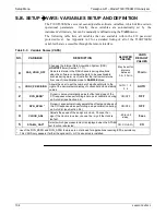
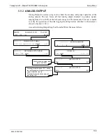
5.9.3.6.
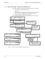
MANUAL CALIBRATION OF THE ANALOG OUTPUTS CONFIGURED FOR VOLTAGE
RANGES
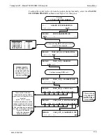
For highest accuracy, the voltages of the analog outputs can be manually calibrated.
Note
The menu for manually adjusting the analog output signal level will only
appear if the AUTO-CAL feature is turned off for the channel being
adjusted (see Section 5.9.3.3).
Calibration is performed with a voltmeter connected across the output terminals and by
changing the actual output signal level using the front panel buttons in 100, 10 or 1
count increments. See Figure 3-9 for pin assignments and diagram of the analog output
connector.
V
+DC Gnd
Recording
Device
V IN +
V IN -
ANALYZER
V OUT +
V OUT -
Volt
Meter
Figure 5-4:
Setup for Checking / Calibrating DCV Analog Output Signal Levels
Table 5-7: Voltage Tolerances for the TEST CHANNEL Calibration
FULL SCALE
ZERO TOLERANCE
SPAN VOLTAGE
SPAN
TOLERANCE
MINIMUM ADJUSTMENT
(1 count)
0.1 VDC
±0.0005V
90 mV
±0.001V
0.02 mV
1 VDC
±0.001V
900 mV
±0.001V
0.24 mV
5 VDC
±0.002V
4500 mV
±0.003V
1.22 mV
10 VDC
±0.004V
4500 mV
±0.006V
2.44 mV
06864D DCN7562
Summary of Contents for T300
Page 2: ......
Page 182: ...06864D DCN7562 ...
Page 227: ...225 This page intentionally left blank 06864D DCN7562 ...
Page 228: ...06864D DCN7562 ...


