Bulkhead Style Optical Panels
Telect LCX Series
Installation Guide
Page 1: ...Bulkhead Style Optical Panels Telect LCX Series Installation Guide ...
Page 2: ...PLICATIONS 15 2 1 Interconnecting IFC to Network Elements 15 2 2 Interconnecting Network Elements 15 2 3 Cross connecting Network Elements 16 2 4 Cross connecting Combinations 16 2 5 Interconnecting Cross connecting with Special Function Modules 17 CHAPTER 3 PANEL INSTALLATION 18 3 1 Installation Considerations 18 3 1 1 Location Space 18 3 1 2 Tools Equipment 18 3 1 3 Inspection 18 3 2 Panel Insta...
Page 3: ...g IFC Fiber 28 4 3 1 2 Installing Routing Network Element Fiber 29 4 3 1 3 Splicing 30 4 3 2 Patching 31 4 3 3 Patching in the LCX H 31 CHAPTER 5 SERVICE 32 5 1 Owner Maintenance 32 5 2 Technical Support 32 5 3 In Warranty Service 32 5 4 Out of Warranty Service 32 5 5 Repacking the Shipment 32 5 6 High Insertion Loss and the Importance of Cleaning Connectors Adapters 33 5 6 1 How to Clean Connecto...
Page 4: ...ts 16 Figure 30 Interconnecting Cross Connecting Along with WDM Splitter Modules 17 Figure 31 Removing Knockouts Installing Plastic Grommets 19 Figure 32 Installing a Standard Split Arc 19 Figure 33 Installing a Standard Isolation Hook Kit 19 Figure 34 Installing an Optional Arc Kit 19 Figure 35 Mounting LCX Panel to Rack 20 Figure 36 Installing Adapter Pack Special Function Modules 20 Figure 37 I...
Page 5: ...ups of fiber cables 1RU models have densities up to 24 fiber terminations Instead of front or rear doors 1RU panels have a removable sliding drawer that can be extended at the front or rear of the chassis to maximize access to fiber connections Pivoting arcs at corner entries and exits provide cable management Entry and exit positions are compatible with entries and exits of other Telect LCX panel...
Page 6: ...iber Splice Trays A 144 splice 4RU LCX panel LCX S141 that houses six splice trays is available but not pictured 24 splice 2RU LCX panel 1 splice tray 48 splice 3RU LCX panel 2 splice trays 72 splice 4RU LCX panel 3 splice trays 96 splice 4RU LCX panel 4 splice trays 2RU 3RU and 4RU fiber splice trays use storage spools to route and store stranded fiber The following figures show termination capac...
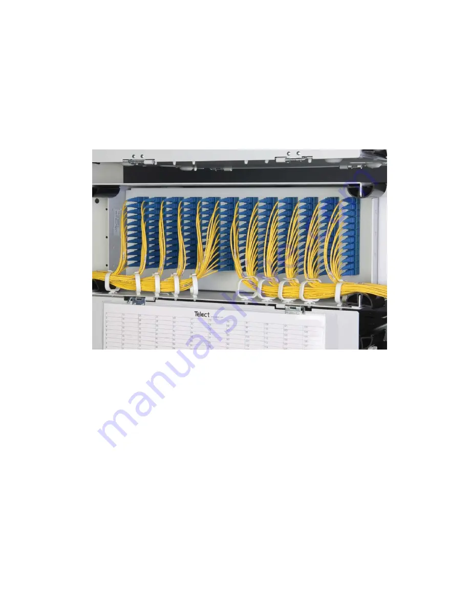
Page 7: ...RU and 4RU splice tray Figure 7 2RU LCX splice panel 24 termination capacity Figure 8 3RU LCX splice panel 48 termination capacity Figure 9 4RU LCX splice panel 72 to 96 termination capacity Each of two splice holders ho lds 112 splices Tie Down Locations for Incoming Outgoing Cable Spoo ls 2 Splice Cover Use either lacing or cable ties to secure cable subunit flexible tubing and or sheathing Figu...
Page 8: ...h plates with six or eight adapters LC SC is available in patch plates with 12 adapters LC UPC and LC APC are available in patch plates with 24 adapters MTP MPO feed through patch plates are available with six and eight adapters All adapters are available in multimode versions and include dust covers Like the chassis most patch plates are available in white or black Fig 17 Figure 13 1RU LCX patch ...
Page 9: ...Modules Empty LCX fiber patch panels can be configured on site with adapter packs and special function modules Telect offers a full line of standard size Wavelength Division Multiplexing WDM modules and splitter modules that can be used in place of adapter packs 1 2 1 MTP Breakout Modules Telect offers both MTP and MPO cassettes that are LGX compatible Standard Adapter Plates Part Number Patch pla...
Page 10: ... 1 509 926 6000 telect com 1 3 Drawings 1 00 25 4 1 25 31 7 15 06 382 4 23 04 585 3 22 35 567 8 19 04 483 7 18 36 466 3 0 12 2 9 1 73 44 0 1 64 41 6 3 55 90 2 1 50 38 1 0 30 7 6 0 06 1 4 11 00 279 4 REAR VIEW ROTATED NOTE Dimensions are in in mm TOP VIEW FRONT VIEW Figure 21 1RU LCX chassis ...
Page 11: ...EW ROTATED NOTE Dimensions are in in mm 10 74 272 9 7 38 187 4 0 12 3 1 0 24 6 2 Ø1 50 Ø38 1 Ø0 26 Ø6 5 0 99 25 3 0 24 6 2 0 12 2 9 TOP VIEW FRONT VIEW 0 18 4 7 0 19 4 8 0 19 4 7 1 76 44 6 2 01 51 0 17 03 432 5 23 00 584 2 22 31 566 7 19 00 482 6 18 28 464 3 3 21 81 6 1 50 38 1 0 10 2 5 3 26 82 8 3 45 87 6 Figure 22 2RU LCX chassis ...
Page 12: ...0 09 2 4 0 19 4 7 REAR VIEW ROTATED NOTE Dimensions are in in mm 10 75 273 0 3 21 81 6 1 50 38 1 7 38 187 5 0 12 2 9 0 24 6 2 Ø1 50 Ø38 1 Ø0 26 Ø6 5 0 99 25 2 0 24 6 2 0 12 2 9 19 00 482 6 23 00 584 2 22 31 566 7 18 28 464 3 2 01 51 0 1 76 44 6 TOP VIEW FRONT VIEW 17 03 432 5 0 18 4 7 0 19 4 8 0 19 4 7 Figure 23 3RU LCX chassis ...
Page 13: ...Ø38 1 Ø0 26 Ø6 5 0 09 2 4 0 19 4 7 6 72 170 6 0 17 4 3 1 29 32 9 REAR VIEW ROTATED NOTE Dimensions are in in mm 10 72 272 4 3 21 81 6 7 36 186 9 0 12 2 9 0 24 6 2 0 24 6 2 0 12 2 9 3 00 76 1 1 76 44 6 TOP VIEW FRONT VIEW 17 03 432 5 0 19 4 8 0 19 4 7 23 00 584 3 22 31 566 8 19 01 482 8 18 32 465 3 Figure 24 4RU LCX chassis ...
Page 14: ...ghts reserved 06 08 17 1 509 926 6000 telect com R6 85 R174 0 R6 85 R174 0 R5 05 R128 3 R5 05 R128 3 R3 39 R86 2 R3 39 R86 1 4 73 120 2 5 69 144 6 1RU Top View 2RU Right Side View 3RU Right Side View 4RU Right Side View FRONT REAR Figure 25 Pullout swing out clearances ...
Page 15: ...cting Network Elements In Figure 27 fiber from one set of network elements is interconnected to a second set To Network Elements LCX Fiber Splice Panel Splice Vault IFC OSP Subunit Tube 900µm 2 3 mm Sheathed Cable Figure 26 Interconnecting splicing facility cable to network elements To From NE1s From To NE2s Multifiber Sheathed Cable LCX Fiber Patch Panel Use rings to help guide and organize stran...
Page 16: ...owever it is easier before panels are racked Avoid removing the knockouts on the top of the top most and bottom of the bottom most LCX panels The knockout plugs also provide fire abatement The hardware for connecting the patch splice together is not included when purchased separately LCX Fiber Patch Panel Network Element 1 I O Patch Cords Front Rear Front Rear NE2 Pigtails NE1 Pigtails Figure 28 C...
Page 17: ...ed to interconnect cross connect the split de multiplexed signals with the network elements In such case Splitting 48 signals three ways requires a 4RU LCX patch panel with 144 adapters De multiplexing 48 signals into two wavelengths requires a 4RU LCX patch panel with 96 adapters Three 3RU LCX Configurable Patch Panels with eight 1 to 3 dual splitters can be used to terminate spliced strands from...
Page 18: ...local codes or ordinances 3 1 1 Location Space LCX fiber panels adapt to standard 19 inch 23 inch or ETSI racks with WECO EIA or ETSI spacing and nominal 3 in extensions beyond the front rack flange Plan the input output upward downward cable feed layout of each panel and its position in the rack before beginning LCX panel installation If you plan to pass fiber strands cable and or tubing through ...
Page 19: ...f the chassis at the entry exit corners Refer to Figure 32 NOTE Two of the provided arcs are longer than the rest These should go on the bottom rear of the LCX chassis Installing an isolation hook kit purchased separately Follow these steps and refer to Figure 33 i Remove the split arc at the top and bottom of the applicable corner entry exit ii Use the two Phillips head machine screws screws with...
Page 20: ...include a ground lug and star washer Use one ground lug with 14 AWG stranded wire per chassis 5 Install adapter packs and or special function modules in configurable LCX fiber patch panels Figure 36 shows a six adapter pack being installed in a 4RU LCX fiber configurable patch panel 6 Push in quick connect plungers at both ends of faceplate to lock pack or module in bulkhead 7 Place a plastic cabl...
Page 21: ...ssis 3 If applicable install adapter packs and or special function modules in configurable LCX fiber patch panels Figure 41 shows a special function module being installed in a 1RU LCX fiber configurable patch panel 4 Push in quick connect plungers at either end of faceplate to lock pack or module in bulkhead NOTE Each shelf of an LCX fiber patch splice combination panel must be grounded separatel...
Page 22: ... 2 Remove the two screws on the fixed swing Fig 43 3 Remove the bulkhead assembly and rotate it Fig 44 4 Remove the hanger and install it on the opposite side Fig 45 5 Reinstall four screws and close the bulkhead Fig 46 Figure 42 Open bulkhead and remove screws Figure 43 Remove screws on the fixed swing Figure 44 Remove assembly and rotate Figure 45 Remove hanger and install opposite Figure 46 Rei...
Page 23: ...originating from the network elements are tied down near the front of the splice tray The unprotected strands or ribbon from the tied down tubes and cables are wound several times around the two spools on the tray One of the spools is for the strands or ribbon from the IFC and the other for the network element leads The bottom of the 2RU 3RU and 4RU LCX fiber splice panels are used for storing coi...
Page 24: ...ement leads exit enter the splice panel at either the same side of the panel IFC at the rear and network fiber at the front or at the two rear corners 1 Route IFC to a rear corner entrance of the LCX fiber splice panel IFC can be routed from the bottom up or top down at either rear corner of the splice panel 2 Measure an additional 83 in 2110 mm and then trim excess IFC 3 Before clamping IFC to pa...
Page 25: ...ch panel entrance Piggy backing also provides cable clearance to lower LCX Splice Panels Th e clam ps can also be secured to LCX Patch Panels u Hook and loop strap inserted through tie down to hold subunits to floor of pane l Cable Clam p A tt a c h c la m p p late t o lo w er tw o ho le s in s id ew a ll f o r bo tt o m up cab le f eed s Clamp Half Bushing Clamp Half Subunit Clamp Plate IFC 144 S...
Page 26: ...is gathered in IFC use a cable clamp at a rear corner just as you would for IFC from a splice vault b If using discrete fiber cables at a front corner entrance use a cable management system such as illustrated below 2 Measure an additional 83 in 2110 mm and then trim excess cable 3 Strip away leading 24 in 610 mm of cable sheathing to expose either stranded or ribbon fiber 4 Select pairs groups of...
Page 27: ...earby adjacent spool 6 Make splices place in holder and then re attach splice cover 7 Fill out designation cards located in holders on the inside of front and rear doors 8 Place tray in panel followed by coil tubing and cables lay them flat on floor of panel Each of two splice holders ho lds 112 splices Tie Down Locations for Incoming Outgoing Cable Spoo ls 2 Splice Cover Use either lacing or cabl...
Page 28: ... on an appropriate interbay storage frame 4 3 Fiber Installation 1RU 4 3 1 Splicing The paragraphs that follow contain installation and routing procedures required for splicing IFC to network elements in a 1RU LCX splice panel 4 3 1 1 Installing Routing IFC Fiber An optional cable clamp 027 1000 1001 is required for installing IFC to an LCX fiber splice panel see Accessories Section 6 1 Route IFC ...
Page 29: ...the LCX fiber splice panel If network element leads are gathered in IFC use a cable clamp at a rear corner just as you would for IFC from a splice vault If using discrete fiber cables at a front corner entrance use a cable management system as illustrated in Figure 56 2 Measure an additional 70 inches 1778 mm and then trim excess cable Cable Clam p 24 Fiber IFC Network Cable Leave sufficient slack...
Page 30: ...e selected holder slot make the splice and then place in holder 6 Re attach splice cover when finished splicing tray 7 Fill out tray label and affix to front of tray 8 Place tray in panel Coil tubes to fit around the central set of six arcs in the tray Do not coil the last eight inches 200 mm of tubing around the arcs These uncoiled lengths of tubing will serve as a service loop allowing splice tr...
Page 31: ...e ties or other restraints to tie pigtails jumpers and or cords to floor of the panel 4 Fill out tray label and affix to front of tray 5 If applicable store excess pigtails jumpers or cords on an appropriate interbay storage frame 4 3 3 Patching in the LCX H Fiber cable can be routed in different patterns in the rear depending on amount of slack storage 900 micron or fiber jumper cables can be anc...
Page 32: ...0 Telect will repair or replace defective products within the limits of the warranty See Repacking for Shipment in this section NOTE Call a Customer Service Representative for a Return Material Authorization RMA before returning any equipment 5 4 Out of Warranty Service The procedure for out of warranty service is the same as for in warranty service however Telect charges a processing fee You must...
Page 33: ...e impurities quickly and thoroughly yet evaporate quickly after wiping dry Always allow the ferrules to air dry thoroughly before reconnecting You may use canned air to clean away debris initially but don t use an aerosol after cleaning polished surfaces Most aerosols contain contaminants If a commercial solution isn t available you may use reagent grade ethyl alcohol nominally USP 99 available at...
Page 34: ... 3A10 055 0000 3A80 MTP MPO 055 0000 MTA06 055 0000 MTA08 SC MM 055 0000 6A20 055 0000 6A82 055 0000 6A22 LC MM 055 0000 5A12 055 0000 5A13 055 0000 2A412 Standard Adapter Plates Part Number Patch plate 6 port FC UPC 055 0000 2010 Patch plate 6 port FC APC 055 0000 2070 Patch plate 8 port FC UPC 055 0000 2080 Patch plate 8 port FC APC 055 0000 2090 Patch plate 6 port ST UPC 055 0000 3010 Patch pla...
Page 35: ...ry Exit Cable Management Arc kit2 KIT CMARC Hook Kit 4RU Front White Black KIT CMHOOK KIT CMHOOK BLK 4RU Rear White Black KIT CMRHOOK KIT CMRHOOK BLK 3RU Front White Black KIT CMHOOK3RU KIT CMHOOK3RU BLK 3RU Rear White Black KIT CMRHOOK3RU KIT CMRHOOK3RU BLK Optical Patch Cords See www telect com Splitter WDM Modules Multifiber Indoor Cable MIC 1 Kit contains hardware for OSP armored cable from 0 ...