Telect GMT Series User Manual Download Page 1

© Telect, Inc.,  All Rights Reserved, 130339-7 A0

1.509.926.6000  ::  telect.com

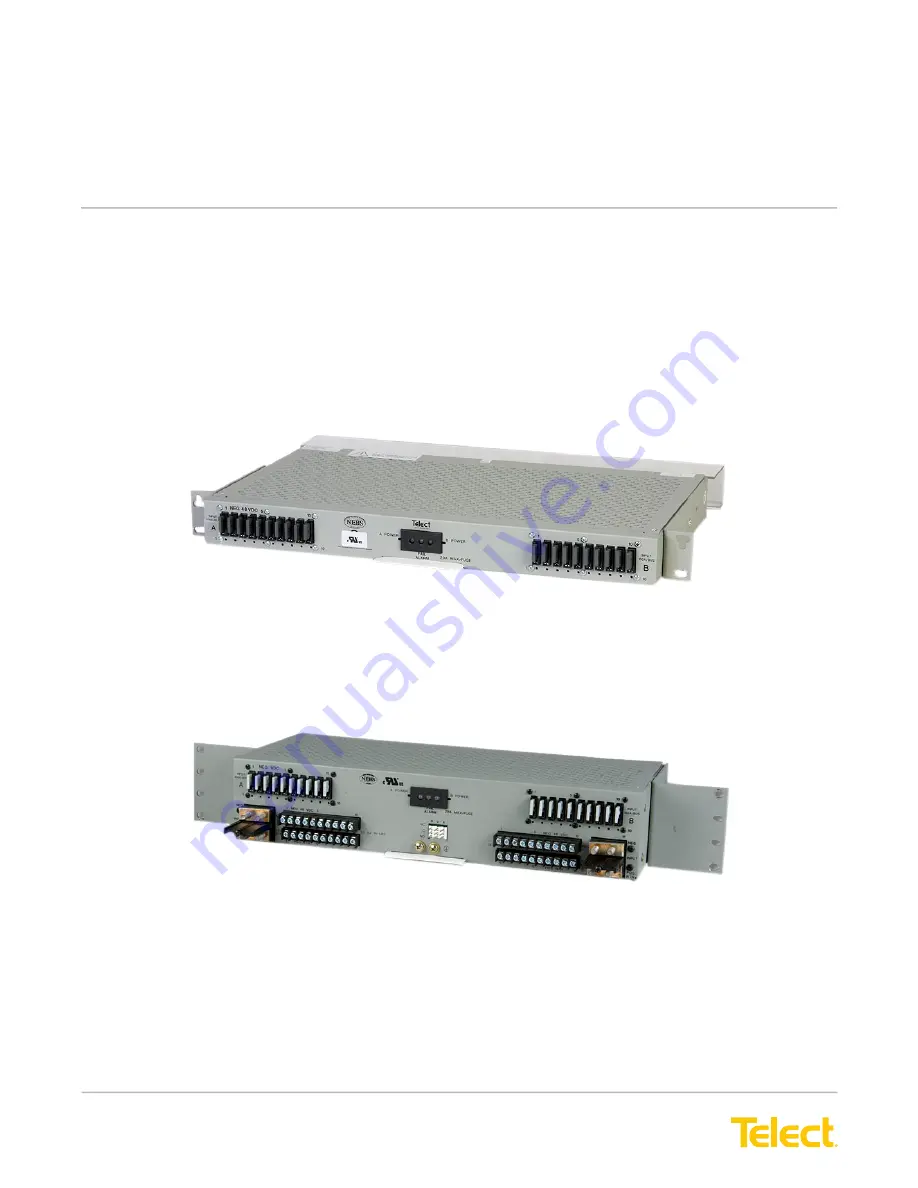
High-Power 20A GMT Series Fuse Panels

Power

  ::  20HPGMTXX 

User Manual

Applys to

 : 20HPGMT05R  ::  20HPGMT05FR  ::  20HPGMT05BNR  ::  20HPGMT05BNR-24  ::  20HPGMT12R-75  ::   


     20HPGMT03R  ::  20HPGMT02R 

Summary of Contents for GMT Series

Page 1: ...Rights Reserved 130339 7 A0 1 509 926 6000 telect com High Power 20A GMT Series Fuse Panels Power 20HPGMTXX User Manual Applys to 20HPGMT05R 20HPGMT05FR 20HPGMT05BNR 20HPGMT05BNR 24 20HPGMT12R 75 20HPGMT03R 20HPGMT02R ...

Page 2: ...tenance 13 1 3 2 In Warranty Service 14 1 3 3 Out Of Warranty Service 14 1 3 4 Repacking for Shipment 14 1 4 Parts Accessories 14 1 5 Diagrams 16 1 5 1 Block Diagram 16 1 5 2 1RU Dimensions 17 1 5 3 2RU Dimensions 18 1 6 Certificate of Conformity 19 List of Figures Figure 1 20HPGMT05BNR 1RU Panel Front and Rear View 1 Figure 2 20HPGMT12R 75 2RU Panel 1 Figure 3 Model 20HPGMT05R Front View 2 Figure...

Page 3: ...ion Alarm circuit board replaceable with panel in service hot swap Minimal rack space one 1 75 EIA or 2 WECO rack unit 1RU for rear access connections 2RU for total front access of dual circuit 10 10 configuration 19 or 23 rack mounting with mounting brackets provided Dual Circuit 20 20 Panel 20HPGMT02R requires a 23 in rack Transparent terminal cover meets electrical and equipment safety standard...

Page 4: ...nels use discrete not modular GMT fuse holders to limit heat buildup when using 15A and 20A GMT fuses Figure 3 Model 20HPGMT05R Front View 1 1 1 Specifications Environment Specifications Temperature range 5 C to 55 C 23 F to 131 F Humidity 5 to 85 and noncondensing Altitude range 197 ft to 13 100 ft 60 m to 4000 m Acoustic noise 0 dBA above ambient Fit Finish Specifications Material Custom color f...

Page 5: ... 1 0 N m max Alarm terminals Wire Wrap 0 045 in square wirewrap pins on 0 156 in centers Use 18 to 22 AWG copper Ground terminals Screws 2 10 Phillips panhead Lugs Single or dual hole compression lug 5 8 in center to center Dual hole lug is recommended Cable Up to 6 AWG copper for single hole lug Conductor size depends on input interruption device Torque 21 in lb 2 5 N m max Screws with cross rece...

Page 6: ...se capacity 20 30 or 40 total both circuits Maximum input interruption device rating 125A for all models except those with noise filters 90A for models with noise filters 20HPGMT05NR 20HPGMT05BNR 24 Maximum output interruption device rating 20A GMT fuse Interrupt rating 450A Short circuit withstand current 450A Alarm contact relay 2A Alarm board power rating 48 Vdc 1W Panel heat dissipation per 10...

Page 7: ...t the fuse positions are oriented so the identification flags face down to provide easy location of a blown fuse when the panel is at the top position of a relay rack or bay GMT splash covers are optional for maximum safety when fuses blow Another unique feature of the GMT panels is a small hole below each fuse position to accommodate color coded optional designation pins Designation pins are usef...

Page 8: ... Along with the standard alarms Models 20HPGMT05BNR and 20HPGMT05BNR 24 include major minor bay alarms Bay alarms are controlled externally to turn on the panel s Form C relay contacts in circuit with external bay devices or connections Whenever a bay alarm occurs the A POWER LED for a major alarm or B POWER LED for a minor alarm will blink until external control is turned off Model 20HPGMT05FR in...

Page 9: ...cuits for A and B are common since both circuits must operate from either the A or B power source The fail safe feature reduces the A and B inputs to 75A maximum for each bus total 150A per panel The fail safe feature also includes the enhanced failure alarms described previously NOTE For the fail safe load sharing to function properly the capacity of each of the user supplied external feeder fuse...

Page 10: ...To prevent problems with the over current protection and supply wiring take care not to overload the circuits Pay attention to equipment nameplate ratings Reliable earthing Maintain reliable earthing of rack mounted equipment Pay attention to supply connections as well as direct connections to the branch circuit i e use of power strips Disconnect device Incorporate an easy to reach disconnect devi...

Page 11: ...however that you perform the testing outlined in the following installation procedure to ensure that no damage has occurred during shipping and handling Both Sides A and B input circuits need to be tested Except for Dual Circuit 20 20 GMT Panels brackets are provided for either flush or extended EIA or WECO mounting in a 19 in or 23 in rack Mount the Dual Circuit 20 20 GMT Panels to a 23 in EIA or...

Page 12: ...lean terminals and stud s 7 Telect recommends that you lightly coat anti oxidant on the lug grounding screw s and surrounding contacting surface 8 Connect the lug to the rear panel using the 10 screw s provided as shown in Figure 9 9 Make sure the input power is off 10 For input wiring a Crimp dual hole compression lugs for 1 4 in studs on 5 8 in 15 9 mm centers onto suitable copper wires 6 to 1 0...

Page 13: ... with enhanced failure alarms included with fail safe feature test at A PWR B PWR and F ALM pins When testing the A PWR and F ALM pins Expect continuity 0Ω between Terminals C and NC Expect an open circuit 00Ω between Terminals C and NO Conversely when testing the B PWR pins Expect an open circuit 00Ω between Terminals C and NC Expect continuity 0Ω between Terminals C and NO 16 Repeat Steps 13 to ...

Page 14: ...entify the circuits If applicable install color coded designation pins to match the fuses 24 Check voltage and polarity at input of loads 25 After you have installed all designated GMT fuses check that the FAIL ALARM LED is still green Again test the alarm relay contacts at R V A F ALM pins on the rear of the panel As before Expect continuity 0Ω between Terminals C and NC Expect an open circuit 00...

Page 15: ...e alarm circuit board may be removed and replaced from the front of the fuse panel You do not need to remove power or otherwise take the fuse panel or the equipment it is feeding out of service to perform alarm board replacement Contact Telect for a replacement alarm board See 1 4 Parts Accessories on page 14 When replacing an alarm board ensure that the keyed connector at the rear wall of the pan...

Page 16: ...equipment The processing fee guarantees a repair estimate and is credited against actual material and labor costs Call Telect Quality at 1 509 926 6000 for more information 1 3 4 Repacking for Shipment 1 Tag the equipment showing owner s name address and telephone number together with a detailed description of the problem 2 Use the original shipping container if possible If you do not have it pack...

Page 17: ...18 12A Yellow Green YEL GRN 102287 102435 19 15A Red Blue RED BLU 102288 102435 20 20A White Green WHT GRN 127240RC 102435 22 Dummy Fuses 132748 GMT Safety Covers 116915 Medium duty GMT fuse puller 06113 03 Table 4 Dual Hole Compression Lug Part Numbers vs Input or Ground Wire Size For 1 4 in Studs on 5 8 in Centers 1 0 AWG 2 AWG 4 AWG 6 AWGa 8 AWG 10 AWG T B 54206 T B Die Code 29 54205 T B Die Co...

Page 18: ...es Fuse Panels Power Models 20HPGMT Table 5 Single Hole Ring Lug Part Numbers vs Output Wire Size For 6 Panhead Screws 22 18 AWG 22 16 AWG 16 14 AWG 12 10 AWG AMP 51863 51863 320619 329697 Panduit PN18 6R M PN14 6RN M 1 5 Diagrams 1 5 1 Block Diagram Figure 12 Power Battery Return and Fuse Circuit ...

Page 19: ...ns are in in mm Max lug width is 0 54 in 13 7 mm 10 32 Panhead Screws are Included 3 0000 Panel m ay be flush mounted or extended by up to 3 in 76 m m in 0 5 in 12 7 mm increments TOP VIEW 0 62 15 8 0 33 8 5 0 30 7 5 0 62 15 9 Max lug width is 0 67 in 17 0 mm 2 27 57 7 0 75 18 9 0 12 3 0 9 63 244 5 1 00 25 4 17 00 431 8 1 25 31 7 1 75 44 5 Transparent Cover 6 32 Panhead Screws 1 4 20 Studs KEPS Nu...

Page 20: ...2 6 17 00 431 8 7 50 190 5 0 12 3 0 NOTE Dim ensions are in in mm www telect com 0 27 6 8 0 62 15 9 M ax lug width is 0 54 in 13 7 mm 0 26 6 6 0 33 8 5 0 62 15 8 M ax lug width is 0 67 in 17 0 mm 6 32 Panhead Screws 10 32 Panhead Screws Bottom Half of Front 1 4 20 Studs KEPS Nuts 1 5 3 2RU Dimensions Telect assumes no liability for the application or use of these products Neither does Telect conve...

Page 21: ... the protection requirements set out in article 4 of EMC Directive 89 336 EEC as per EN 55022 94 with A1 95 A2 97 class A EN 61000 3 2 95 EN 61000 3 3 95 EN 300 386 V1 2 1 00 03 and ETS 300 132 2 and in accordance with the Agreement on Mutual Recognition between the United States of America and the European Community Sectoral Annex for EMC this U S Conformity Assessment Body hereby certifies attes...

Page 22: ... Telect Inc All Rights Reserved 130339 7 A0 1 509 926 6000 telect com 20 High Power 20A GMT Series Fuse Panels Power Models 20HPGMT This page intentionally left blank ...

Reviews: