background image

VS1 Installation, Configuration & Operating Guide

105

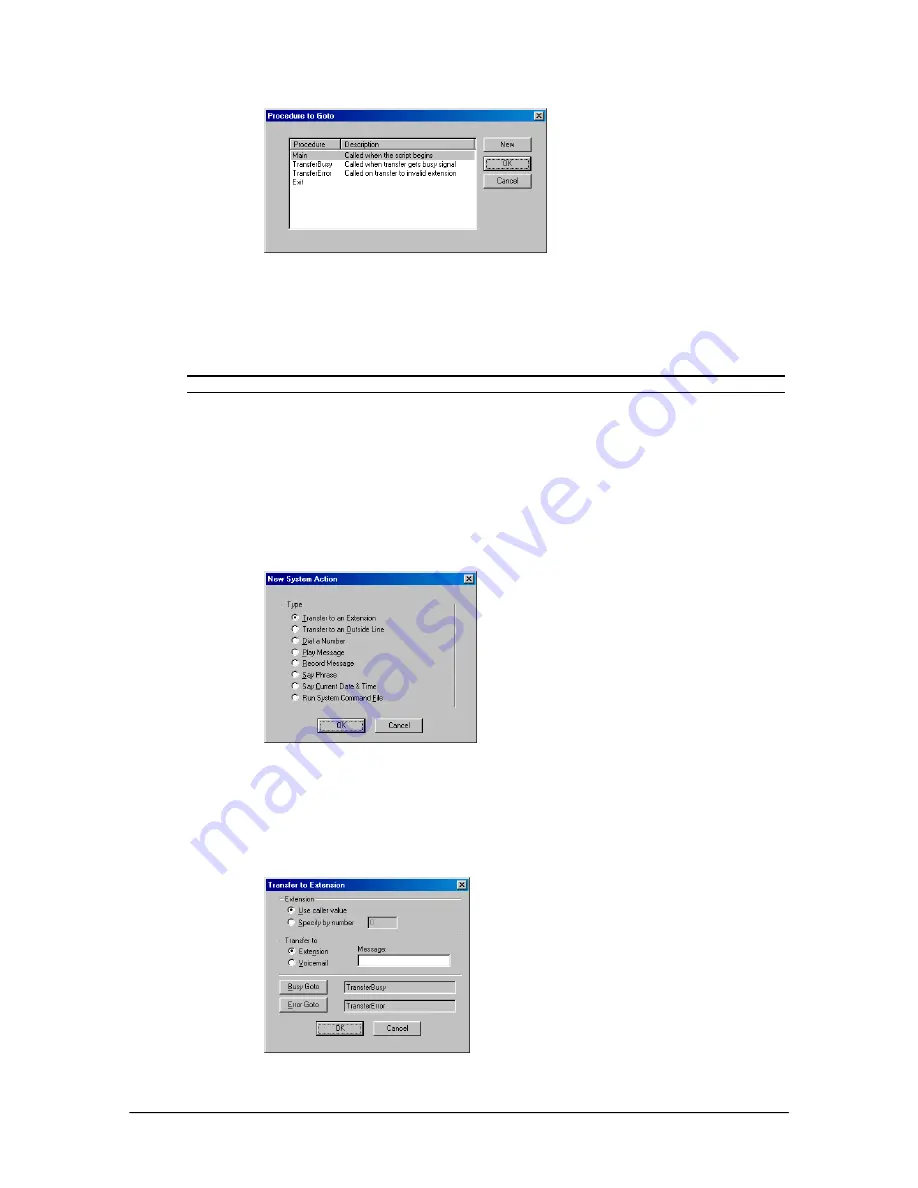
Procedure to Goto
dialog box

2.


Double-click the desired Procedure. 


The Procedure appears beside the 

Goto Procedure

 button. 

Note

 Selecting 

the 

Exit

 Procedure disconnects the call. 

Assigning a System Action

After creating a Caller Response, you are returned to the 

Specify System Actions for Caller

Responses

 window. To assign a system action:

1.


Select 

System Actions

 and click 

New

.


The 

New System Action 

dialog box appears displaying the options shown below:

New System Action
dialog box

System Action – Transfer to an Extension

Clicking 

Transfer to Extension

 in the 

New System

 dialog box brings up the 

Transfer to

Extension 

dialog box.

Transfer to
Extension dialog box

Summary of Contents for VS1

Page 1: ...m Installation Configuration Operating Guide Intended for use in VS1 Systems running TVS Software 2 10 June 2003 Man Rev 3 Telecor Inc 1114 Westport Cr Mississauga Ontario Canada L5T 1G1 Tel 905 564 0801 Fax 905 564 0806 ...

Page 2: ...ding Environmental Specifications See the Hardware section for specific product specifications FCC Information This equipment complies with Part 68 of the FCC rules On the bottom of this equipment there is a label that contains among other information the FCC Registration Number and Ringer Equivalence Number REN for this equipment The telephone company may require this information prior to connect...

Page 3: ...étiquette d Industrie Canada identifie le matériel homologué Cette étiquette certifie que le matériel est conforme aux normes de protection d exploitation et de sécurité des réseaux de télécommunications comme le prescrivent les documents concernant les exigences techniques relatives au matériel terminal Le Ministère n assure toutefois pas que le matériel fonctionnera à la satisfaction de l utilis...

Page 4: ... electrician Do not defeat the safety purpose of the polarized plug 9 Do not allow anything to rest on the power cord Do not locate this product where the cord will be abused by persons walking on it 10 Do not use an extension cord with this product s AC power cord Equipment not associated with the telephone system should not be plugged into the same AC outlet 11 Never push objects of any kind int...

Page 5: ...ions 12 10Base T Network Interface Card 13 Hardware Specifications 13 T1 Interface Card 14 Hardware Specifications 14 TVS VGA Video Card 15 Hardware Specifications 15 SC200 Switch Card 16 Hardware Specifications 16 Computer Telephony Interface Module CTIM 17 Hardware Specifications 17 PC Option Module PCOM 18 Hardware Specifications 18 ACD Status Board 19 ACD Status Board Manufacturer 19 HARDWARE ...

Page 6: ...rk Interface Card Checklist 41 Installing a T1 Interface Card 42 Ordering T1 Service 42 Installing the T1 Interface Card 43 Cable Installation 44 Installing the CTIM 45 CTIM Checklist 45 Installing the PC Option Module PCOM 46 PCOM Checklist 46 CREATING AN EMERGENCY BOOT FLOPPY 47 TEL SITE 49 OVERVIEW OF TEL SITE 51 Tel Site Windows 52 The Connection Window 52 The Configuration Window 53 The Explo...

Page 7: ...em Access RSA Password 78 Uploading Files to a Site 78 Reloading Configuration Changes 79 System Reset Required 80 VS1 EDITOR 81 OVERVIEW OF VS1 EDITOR 83 ACTIVATION KEYS 84 Receiving Activation Keys 84 Installing Activation Keys 85 ADAPTER SETUP 86 AUTOMATIC CALL DISTRIBUTION 87 Creating an ACD 88 ACD Account Codes 88 Configuring an ACD 90 Over _____calls per _____agents 91 Queued call age is ___...

Page 8: ...efault Command Scripts 117 Running a Command Script from the TVS Command Prompt 118 Running a Command Script from a Phone 118 Running a Command Script from an Auto Attendant 118 System Commands 120 CONFERENCE ROOMS 125 DID DNIS ROUTING 126 Configuring a Port for T1 Service 126 Assigning the Port as a CO Line 126 Configuring the Port for DID or DNIS 127 Setting up a DID or DNIS Routing Table 128 FO...

Page 9: ...4 Selecting a Call 174 Connecting to a Call 174 Placing a Call On Hold 174 Taking a Call Off Hold 174 Disconnecting a Call 174 Transferring a Call to an Extension Unannounced 174 Transferring a Call to an Extension Announced 175 Transferring a Call to an Extension s Voice Mail 175 Making an Outside Call 175 Making an Inside Call 175 Overview of Connect 176 Product Features 177 Requirements 177 Inc...

Page 10: ...ting 191 Setting Up Your Name in the Dial By Name Directory 191 Sending a Message to an Individual or a Work Group 191 Sending a Message to an Individual 191 Sending a Message to a Range of Extensions 192 Sending a Message to a Work Group 192 Forwarding a Voice Mail Message to an Individual or a Work Group 192 Forwarding a Voice Mail Message to an Individual 192 Forwarding a Voice Mail Message to ...

Page 11: ... 218 RECORDING VOICE FILES 220 Recording Using the Voice Message Recorder 220 Recording Using the PEU 205 or DCU 220 Playing a Voice File Using the Command Prompt 221 PRE RECORDED MESSAGE LIST 222 Phrase List 223 SCHEDULED DISK OPTIMIZATION 224 STATION MESSAGE DETAIL RECORDING SMDR 225 Designating SMDR Output Files 226 Backing up SMDR Output Files 226 Command Script Sample to Copy SMDR Files on Tu...

Page 12: ...RFACE CARD CONFIGURATION 242 T1 Interface Card Parameter Setup Using Tel Site 242 T1 Interface Card Setup Using VS1 Editor 247 Adapter Setup 247 Configuring a T1 Port as a CO Line 248 Configuring a T1 Port for DID or DNIS 248 Setting Up a DID or DNIS Routing Table 249 T1 Interface Card Diagnostics 251 T1 Status Screen 252 T1 Interface Card Checklist 255 GLOSSARY OF TERMS 256 INDEX 266 ...

Page 13: ...re available in the form of Computer Telephony Integration CTI applications or desk phones The system is managed with the Tel Site system management application and configured with the VS1 Editor configuration application The diagram below shows the main components of the Telecor VS1 phone system The components of a Telecor VS1 phone system Telecor Voice Server Model 200 CTI Client Applications At...

Page 14: ...tation Message Detail Recording SMDR information Also includes a glossary of terms Section 6 provides a comprehensive Index Conventions in this Guide This guide is designed to help you install and configure the Telecor VS1 phone system quickly and efficiently There are some words and symbol conventions used throughout the guide to help you along the way If you are not at the system site off site o...

Page 15: ...ine syntax or file names argument Indicates an argument for which you must supply a value x An argument or a constant within braces is required Do not type the braces when entering the value x An argument or a constant within square brackets is optional Do not type the brackets when entering the value x y z Constants or arguments separated by a vertical bars requires a choice The Telecor Voice Ser...

Page 16: ...Hardware ...

Page 17: ... PV PEU 205 Port Expansion Unit Model 200 PV PEU 200 Dry Contact Unit Model 100 PV DCU 100 Cut Over Box PV HWC P10 32 Port Host Adapter Card PV HA2 032 64 Port Host Adapter Card PV HA2 064 Caller ID Option Module PV HWC C10 10Base T Network Interface Card PV HWC E10 T1 Interface Card PV HWC T10 TVS VGA Video Card 041 000 0013 SC200 Switch Card 701 000 0044 Computer Telephony Interface Module CTIM ...

Page 18: ...nabling you to make fast reliable programming changes The modem card is identified by its two RJ 11 adapters Only one modem can be installed in the TVS The TVS comes with a 32 port Host Adapter Card already installed You can install a maximum of four Host Adapter Cards in the TVS For information on installing additional Host Adapter Cards see Installing a Host Adapter Card page 35 Telecor Voice Se...

Page 19: ...2 4 COM 1 5 COM 3 Internal RSA modem 6 Floppy Drive 7 LPT 2 8 Real time Clock Calendar 9 SC200 Switch Card 10 Available 11 Available Default setting for Network Interface Card 12 Reserved for PS 2 mouse port on current system board 13 Numeric Coprocessor 14 IDE Controller 15 SC200 Switch Card Floppy Disk drive On Off button Power LED indicator HDD LED Indicator Reset button TVS front and back view...

Page 20: ...33 64 310 317 HA200 Host Adapter ports 65 96 or T1 Interface Card 1 318 31F HA200 Host Adapter ports 97 128 or T1 Interface Card 0 320 327 HA200 Host Adapter ports 129 160 328 32F HA200 Host Adapter ports 161 192 340 35F Network Interface Card 379 37B LPT 1 3E8 3EF COM 3 3F8 3FF COM 1 All port addresses are listed in hexadecimal format ...

Page 21: ...figured as CO ports If a power failure occurs the ports cut over to ports 5 through 8 respectively if ports 5 through 8 are configured as extensions The PV PEU 250 can be used as any PEU in a system It does not contain external device contacts External devices are connected to TVS via the Dry Contact Unit Model 100 PV DCU 100 Note If your current TVS software version is prior to 2 9 only the first...

Page 22: ...Hardware Specifications Dimensions WxHxD 16 5 x 3 x 13 5 Weight 27 lbs Power Requirements 120 VAC Temperature 4 38 C operational Humidity 5 95 non condensing Standards Compliance FCC Part 15 FCC Part 68 UL1950 Power Consumption max 120VA ...

Page 23: ...n Units The PV DCU 100 provides connections for two speakers zones two music inputs and two dry contact relay outputs It is connected to the switch card in the TVS PV DCU 100 Hardware Specifications Dimensions WxHxD 16 5 x 1 75 x 2 75 Weight 1 lb 6 oz Power Requirements No power required Temperature 4 38 C operational Humidity 5 95 non condensing Standards Compliance FCC Part 15 FCC Part 68 UL1950...

Page 24: ...stems Note If your VS1 system uses the Port Expansion Unit Model 250 you do not need a separate cut over box Cut over functionality is built into the PEU Model 250 Note When installing a new system Telecor recommends that the Cut Over Box cable connections are made after the system has been installed the software configured and all stations have been tested and verified This aids in determining wh...

Page 25: ... offers a 64 port model The 64 port Host Adapter Card supports four PEUs giving you 16 ports per PEU for a total of 64 ports Installing three 64 port Host Adapter Cards expands the number of ports to 192 64 Port Host Adapter Card Hardware Specifications Dimensions 13 5 x 4 Weight 32 Port Host Adapter Card 9 oz 64 Port Host Adapter Card 10 3 oz Power Requirement 5 Vdc from ISA Bus Adapter Specifica...

Page 26: ...t Expansion Unit Model 200 PV PEU 200 or Port Expansion Unit Model 205 PV PEU 205 The Caller ID module is not used with the Port Expansion Unit Model 250 PV PEU 250 The Model 250 contains integrated Caller ID circuitry on all 16 ports The Caller ID Option Module Hardware Specifications Dimensions 7 25 x 2 5 Weight 3 oz Power Requirements 5 Vdc and 5 Vdc supplied by the PEU Standards Compliance FCC...

Page 27: ...be installed in the Telecor Voice Server TVS if you want to log on to a Novell network or an NT 4 0 server running File and Print Services for Netware FPNW 10Base T Network Interface Card Hardware Specifications Dimensions 6 25 x 2 75 Weight 3 5 oz Power Requirement 5 Vdc from ISA Bus Adapter Specifications RJ 45 connector Architecture 16 Bit Industry Standard Architecture ISA bus Standards Compli...

Page 28: ...art A maximum of two T1 Interface Cards can be installed in the TVS The following table shows the number of T1 channels and Analog CO lines that can be configured for each T1 card installed in the TVS Number of T1 Cards T1 channels Maximum of PEUs Maximum Analog CO lines Maximum Total Ports 0 0 12 96 192 1 24 10 72 184 2 48 8 48 176 T1 Interface Card Hardware Specifications Dimensions 13 5 x 4 Wei...

Page 29: ... you do not plan to connect a monitor to the system the video card is required for operation and must remain installed VGA Video Card Hardware Specifications Dimensions 6 25 x 3 75 Weight 3 2 oz Power Requirement 5 Vdc from ISA Bus Adapter Specifications DB15 connector Architecture 16 Bit Industry Standard Architecture ISA Standards Compliance FCC Part 15 ...

Page 30: ... has a connection for an external fan with a fan fault monitor In addition it provides for monitoring of the case temperature The switch card is also responsible for processing system resets SC200 Switch Card Hardware Specifications Dimensions 13 5 x 4 Weight 9 oz 258 grams Power Requirement 5 Vdc and 12 Vdc from ISA Bus if external fan is connected Adapter Specifications DB15 connector Architectu...

Page 31: ...for the Telecor Attendant and Connect applications The CTIM is an external device with a headset jack intended for use only with the VS1 phone system CTIM Hardware Specifications Dimensions 2 6 x 2 6 x 1 1 Weight 2 8 oz Power Requirements Powered by PEU Temperature 10 50 C operational Humidity 5 95 non condensing operational Adapter Specifications DB 9 Serial Port RJ 11 Line RJ 22 Headset ...

Page 32: ...cor Connect users can use their computer screen for call processing and keep the phone on their desk Keeping a phone on the desk also allows calls to be received when the computer is turned off PC Option Module PCOM cable not pictured Hardware Specifications Dimensions 3 25 x 2 5 Weight 3 oz Power Requirements Powered by PEU Temperature 10 50 C operational Humidity 5 95 non condensing operational ...

Page 33: ...e Telecor Voice Server TVS or the Port Expansion Unit PEU The ACD Status Board is connected to the VS1 business telephone system through the ACD Status Phone The ACD Status Phone is functionally identical to the Display Phone Model 200 DP200 except that the display is customized to monitor ACD status The ACD Status Board serves as an external monitoring display of the ACD Status Phone The ACD Stat...

Page 34: ...than one PEU verify that each port is correctly identified before changing switch settings To configure the PEU 250 1 Use the pushbutton switches next to each port jack to set the port as a CO Line or Extension CO Line button in Extension button out Note If your current software version is prior to 2 9 only the first eight ports on the PEU Model 250 are configurable as CO lines Note In order for C...

Page 35: ...cks on the front of each PEU Label the first PEU with ports 1 16 and the second PEU with ports 17 32 and so on It is recommended that the PEU 205 serve as the first PEU on the system 2 Remove the top panel on the PEU WARNING Do not remove the smaller top panel which covers the power supply The power supply area contains hazardous voltages and has no adjustable settings 3 Locate the station CO jump...

Page 36: ...s to the right side for CO ports and set the digital blue jumpers based on having Internal Caller ID or External Caller ID Jumper Settings 5 Repeat Steps 3 and 4 to set the jumpers for Ports 2 8 6 When finished replace the panel on the PEU 7 Repeat Steps 1 6 for additional PEUs Port 1 jumper settings Analog black Digital blue Remote Power red Jumpers inside the PEU ...

Page 37: ...er Boxes Connections are then made with RJ11 patchcords from the Cut Over Box to the CO Ports on the PEU 250 or PEU 205 see Connecting the Cut Over Box page 33 If your installation does not include Cut Over Boxes then simply connect the CO lines to the designated CO ports on the PEU 250 or PEU 205 Station field wiring and Telco Demarc lines are terminated onto TM 16X3 or TM 8X3 terminal blocks see...

Page 38: ...50 or PEU 205 see Connecting the Cut Over Box page 33 If your installation does not include Cut Over Boxes then simply connect the CO Lines to the designated CO ports on the PEU 250 or PEU 205 Station field wiring and Telco Demarc lines are terminated onto TM 16X3 or TM 8X3 terminal blocks see Terminal Blocks page 25 Telecor recommends that the terminal blocks be arranged in an orderly manner on a...

Page 39: ...Blue Pair Signal Pair 1 Analog Voice Pair 2 Digital Pair 3 Remote Power Terminal Blocks The Prewired 66 Blocks with Modular Telephone Jacks should be used for interconnection between the RJ11 jacks of the PEUs and the station field wiring and Telco Demarc lines Each CO or station line from the terminal block is connected to the corresponding CO or station port on the PEU with an RJ11 patchcord Two...

Page 40: ...n the PEU 2 Plug the Power cord into the TVS and then connect it to a power strip The Power LED on the PEU 250 is lit green to indicate that the power is on The Status LED on the PEU 250 is lit green to indicate that the PEU is connected to the TVS 3 Plug in a keyboard and VGA monitor This is required to create an emergency boot floppy page 47 Connecting the TVS to the PEU 250 Plug in the Power Co...

Page 41: ...d of the 26 pin data cable in the Host Adapter port on the TVS plug the other end of the 26 pin data cable in the Host Adapter port on the PEU 3 Plug the Power cord into the TVS and then connect it to a powerstrip 4 Plug in a keyboard and VGA monitor This is required to create an emergency boot floppy page 47 Program the T1 Interface Card using the T1 Edit program in Tel Site Connecting the TVS to...

Page 42: ...e 35 To daisy chain a second PEU off the first PEU complete the following steps 1 Connect PEU 1 to the Host Adapter port on the TVS as described on page 26 2 Plug a 26 pin data cable in the To Additional PEU port of PEU 1 3 Plug the other end of the 26 pin data cable in the Host Adapter port on PEU 2 Daisy chaining a second PEU from the first PEU If you want to add a third PEU install an additiona...

Page 43: ...to the Telecor VS1 phone system to make a test announcement and then adjust the volume level on the paging equipment as necessary Connecting Music Inputs on a PEU 205 The music inputs are for audio sources such as radios music services tape players or CD players They are used for music on hold and promotions on hold Each CO port can be configured for a specific music source CO ports can also be co...

Page 44: ... is normally open and completely isolated from the VS1 phone system and from ground The maximum open circuit voltage for either contact is 24 volts AC or DC The maximum current switched by either contact is 0 5 amps Installing the Dry Contact Unit Model 100 To connect the TVS to the DCU complete the following steps 1 Plug one end of the 15 pin cable in the Cable A jack on the TVS 2 3 Plug the othe...

Page 45: ...CU The music inputs are for audio sources such as radios music services tape players or CD players They are used for music on hold and promotions on hold Each CO port can be configured for a specific music source CO ports are also configurable to play digital recordings stored on the TVS hard drive The music inputs on the DCU accept 600 ohm low impedance signals To connect a device to the music in...

Page 46: ...stallation Checklist Configure each PEU by setting the jumper settings for each port Mount the PEU to the wall or in the 7 x 19 rack Use the cables to connect the TVS to the first PEU and then mount the TVS Connect additional PEUs by installing additional Host Adapter Cards and then daisy chaining them from the first PEU Connect external contacts ...

Page 47: ...t CO port on the PEU and then plug it into Port 1 To Phone Company on the Cut Over Box 2 Use a second RJ 11 Cable to connect the first CO port on the PEU to Port 2 To CO Port on the Cut Over Box 3 Disconnect the RJ 11 cable from the first Station port on the PEU and then plug it in to Port 4 To Phone on the Cut Over Box 4 Use a third RJ 11 cable to connect the first Station port on the PEU to Port...

Page 48: ... power outage occurs the Cut Over Box automatically switches the connected CO lines to their dedicated extensions Cut Over Box Checklist Mount the Cut Over Box in the rack or to the wall Disconnect the RJ 11 cable from the first CO port on the PEU and then connect it to Port 1 on the Cut Over Box Connect the first CO port on the PEU to Port 2 on the Cut Over Box Disconnect the RJ 11 cable from the...

Page 49: ...nce during installation Note Each Host Adapter Card has a unique Serial Number The TVS uses the Serial Number of the first Host Adapter Card ports 1 32 as the System ID Number The System ID Number is used to authenticate Activation Keys for that particular TVS Replacing the Host Adapter Card configured for ports 1 32 requires new Activation Keys for that TVS 32 Port Host Adapter Card 64 Port Host ...

Page 50: ...e front facing forward 3 Locate an available ISA slot and then remove its slot cover from the back of the TVS case 4 Insert the Host Adapter Card into the selected ISA slot and then secure it with the screw from the slot cover 5 Connect the new Host Adapter Card to the PCM Bus connector cable already attached to the first Host Adapter Card and the Switch Card PCM Bus ribbon connection 6 Replace th...

Page 51: ... the system and then remove the TVS cover Locate an available ISA slot and then remove its slot cover Install the Host Adapter Card in the TVS Connect the Host Adapter Card to the PCM Bus cable in the TVS Replace the TVS cover and reconnect the Host Adapter cable Plug in and turn on the system and then reconnect CO lines to the PEU Connect additional PEUs to the TVS ...

Page 52: ...connect the CO lines from the PEU and then turn off the system Unplug the PEU and remove its cover 2 Find the two male standoffs in the PEU They are located on either side of the 50 pin connector Male Standoffs in the PEU Note Some PEUs have female standoffs instead of male standoffs To install the Caller ID Option Module on a PEU with female standoffs place the holes on the Module over the female...

Page 53: ...hat Caller ID service has been activated To verify the Caller ID Option Module 1 Using the Terminal window in the Tel Site system management application type ls at the TVS Command prompt This displays a list of all ports and their status 2 Press the SPACEBAR to open the Polling window in the Line Status window The first column represents a device polled and responding correctly the second column r...

Page 54: ... cover and then connect the RJ 45 cable from the Network to the Connector on the 10Base T Network Interface Card 5 Plug in the system and then turn the power on Reconnect the CO lines to the PEU Configuring the 10Base T Network Interface Card The TVS automatically detects the presence of the 10Base T Network Interface Card Complete the following steps to connect to the network Note If your system ...

Page 55: ... in the Reference section to redirect SMDR files through a network 10Base T Network Interface Card Checklist Disconnect the CO lines from the PEU turn off the system and then remove the TVS cover Locate an available 16 bit ISA slot and then remove its slot cover Install the 10Base T Network Interface Card in the TVS Replace the TVS cover and then connect the RJ 45 cable from the Network to the Con...

Page 56: ... have a Host Adapter Card installed and a PEU is configured for Ports 96 128 or Ports 65 96 change the PEU port assignments before configuring the T1 Interface Card T1 Interface Card Ordering T1 Service Before installing a T1 Interface Card determine what type of service is required on site and then order T1 service from the local phone company When placing an order provide the FCC ID number from ...

Page 57: ...ith D4 If ESF framing mode is available request B8ZS Bit Eight Zero Suppression line coding If ESF is not available AMI Alternative Mark Inversion line coding is usually used Installing the T1 Interface Card To install the T1 Interface Card complete the following steps 1 Verify that the switches on the T1 Interface Card are set to the correct positions Switches on the first T1 Interface Card shoul...

Page 58: ... Card make the cable connection from the Telco Demarc T1 repeater point to the RJ48C jack on the end of the T1 Interface Card Telecor provides a cable with connectors If a longer cable is required it must be constructed from Category 5 twisted pair wiring connected to pairs 1 and 2 with an RJ48C connector at each end T1 cable wiring diagram See T1 Interface Card Configuration in the Reference sect...

Page 59: ...onductor RJ 11 patch cord from the wall jack to the RJ 11 jack labeled Line on the CTIM 5 Connect a headset to the RJ 22 jack labeled Headset on the CTIM 6 Set the Ear Mic and Sidetone volume control jumper settings on the CTIM for the headset or handset you use The table below shows the volume settings for Ear and Mic 7 Set the Sidetone to Hi or Lo according to user preference The Sidetone is set...

Page 60: ...turn off the computer Locate an available 9 pin or 25 pin serial port on the back of the computer 2 If there is not an available serial port on the computer you need to install one 3 Connect the 9 pin DB9 female connector of the PCOM cable adapter to the 9 pin DB9 male connector of the computer 4 Connect the phone line from the station jack to one of the RJ 11 jacks on the PCOM 5 Connect the phone...

Page 61: ...ton the server The server restarts 3 When the VS1 Options menu appears press 2 to select the VS1 Configuration option 4 On the VS1 Configuration menu press 4 to select the Create an Emergency Boot Floppy option 5 Insert the high density write enabled disk into Drive A of the TVS and then press ENTER The TVS formats the disk then copies the necessary files to it In addition to copying the files nee...

Page 62: ...Tel Site ...

Page 63: ...ction methods available for connecting to a site Finally it provides basic Tel Site operating instructions which cover the following 1 Connecting to a site 2 Downloading any changed files from a site 3 Accessing the VS1 Editor to change site configurations 4 Uploading files to a site 5 Reloading Configuration changes The Tel Site application is available for download from the VS1 Dealer Page of th...

Page 64: ...hen the application is first started After setting up a customer site profile see Setting up a New Site page 56 the Connection window is where you can connect or disconnect from a site In the Connect to customer site group box there is a Connect and Disconnect command button Once connected information about the Telecor Voice Server at the site is displayed This includes site information such as th...

Page 65: ...r Once configured the changes are uploaded to the customer TVS and put into effect The Configuration window is also used to configure a T1 Interface Card by clicking T1 Edit See T1 Interface Card Parameter Setup Using Tel Site in the Reference section for more information Note Typically the Connection window is used to connect to a customer site but the Configuration window can be opened prior to ...

Page 66: ...window shows the amount of free disk space available on the TVS The Explorer window design is similar to the Windows Explorer and many of the features are the same However you cannot place or delete files in the Recycle Bin In addition the Tel Site application considers certain folders and files on the customer TVS as critical to operation These critical files and folders cannot be deleted WARNING...

Page 67: ...on information from a remote site For example you can capture a T1 setup and create a text file for later reference if the file does not exist it is created automatically The toolbar has four buttons used for the Terminal window Terminal Window Capture Window Timed Capture and Clear Capture buttons The latter three buttons appear dimmed or unavailable until the Terminal window is activated Termina...

Page 68: ... Name text box enter a name or description for the customer site 5 Click Next 6 Leave the Phone Number text box blank This box will be filled in later when you connect to the TVS for the first time 7 Leave the RSA password text box blank If the TVS is later assigned a Remote System Access password then you will be instructed to fill this box in See Remote System Access Password on page 78 for more...

Page 69: ...he site This name serves both as the site name and the folder name such as XYZ Corp in the illustration If you choose to keep customer sites on a drive that does not support long file names you will need to use a short name for the customer site You can later change the site name to something more descriptive if you like Tel Site does not require that the customer site name and the folder name rem...

Page 70: ...for the on site connection is a modem to modem connection through two Telecor Port Expansion Unit PEU extension ports TVS Configuration If connecting to the TVS for the first time the TVS Configuration steps do not need to be followed as this configuration is enabled by default Refer to these steps only if required to revert back to an on site connection The on site configuration tells the modem w...

Page 71: ...cted to the TVS modem is configured as a Modem Fax port with the extension 599 the extension number 599 is reserved for a Modem Fax port By default extension port 16 is configured in this manner Modem Fax Port Configuration 8 Click the Save button in the toolbar 9 If steps 4 or 7 had to be changed from the default settings use your current connection method to upload the new settings to the custom...

Page 72: ... which is configured by default as a Modem Fax port with the extension number 599 Another telephone cord is run from the Tel Site laptop or PC to an unused extension port on the PEU Alternatively the telephone cord from the Tel Site computer does not need to be directly connected to the PEU It can be plugged into the data port of a Telecor DP200 Display Phone or into a wall jack of a station exten...

Page 73: ... not directly to the modem in the TVS Connection window 2 From the File menu click Site Selection The Site Selection window appears 3 Select the site from the Site Name column 4 Click Edit Site The Connection dialog box appears 5 If an RSA password is required to enable the Tel Site modem to communicate with the TVS enter it in the RSA password text box See Remote System Access RSA Password on pag...

Page 74: ...tem Configuration 2 pane of the VS1 Editor program set the modem to answer on the first ring In each configuration make sure that PEU Port 16 is configured as a Modem Fax port with the extension 599 Using your current connection method upload the new configuration settings only if changed from default to the customer TVS and reload the changes Connect a standard telephone cord between the line jac...

Page 75: ...through Tel Site click the Configuration window button in the toolbar 2 Click the VS1 Editor button The VS1 Editor configuration program opens 3 In the Tree Control display click System Configuration 2 4 In the Init String text box check that the end of the modem initialization string reads S0 1 S0 1 sets the modem to answer on the first ring By default this setting is already in place 5 Click the...

Page 76: ...S and reload the changes See Tel Site Basic Operation on page 76 Hardware Setup Prior to making the necessary hardware changes ensure the TVS is configured to support the TVS Modem as an Extension connection see page 63 The diagram below shows the hardware setup for a modem as an extension connection A standard telephone cord is run from the line jack of the TVS modem to PEU port 16 configured as ...

Page 77: ...phone number to dial If the Tel Site call is to be answered by an Auto Attendant enter five or six commas after the phone number and then the extension number 599 Each comma is used as a 1 second delay in the dialing process to give the Auto Attendant time to answer before it receives the digits 599 The number of commas used may vary depending on how long it takes for the Auto Attendant to answer ...

Page 78: ...9 Using your current connection method upload the new configuration settings only if changed from default to the customer TVS and reload the changes Connect a standard telephone cord between the line jack of the TVS modem and PEU Port 16 which is configured by default as a Modem Fax port In the Connection dialog box of the Site Selection window enter an RSA password if required Enter a phone numbe...

Page 79: ...open through Tel Site click the Configuration window button in the toolbar 2 Click the VS1 Editor button The VS1 Editor configuration program opens 3 In the Tree Control display click System Configuration 2 4 In the Init String text box check that the end of the modem initialization string reads S0 1 S0 1 sets the modem to answer on the first ring By default this setting is already in place Modem ...

Page 80: ...enu click Site Selection The Site Selection window appears 2 Select the site from the Site Name column 3 Click Edit Site The Connection dialog box appears 4 If an RSA password is required to enable the Tel Site modem to communicate with the TVS enter it in the RSA password text box See Remote System Access RSA Password on page 78 for more information 5 In the Phone number text box enter the phone ...

Page 81: ...n changes Dedicated CO Line to TVS Modem Connection Checklist In the System Configuration 2 pane of the VS1 Editor program set the modem to answer on the first ring Using your current connection method upload the new configuration setting only if changed from default to the customer TVS and reload the changes Connect the CO line from the telephone company demarc to the line jack of the TVS modem I...

Page 82: ...ne system from an external phone not connected to the system For example you are off site and want to access an outside line from the office You perform the normal DISA steps of pressing then your extension and then your DISA account DISA for the Tel Site application uses the same procedures as normal DISA activity The only difference is that Tel Site performs the steps automatically to connect TV...

Page 83: ... DAY configuration 3 Select the CO port that is shared with the TVS modem 4 Under Rings set the CO port to ring the first target for two rings 5 Under Target Ports set the target by typing null The null device doesn t ring a physical extension It gives Tel Site time to send the DISA sequence to the TVS 6 Set the number of rings for the remaining targets according to your configuration 7 Select the...

Page 84: ...figuration 3 In the Port Configurations pane select the Extension port of a user you want to give a DISA password 4 In the DISA Password text box enter a five digit number ranging from 00000 99999 By default the DISA Password is set to 1 which means no password has been assigned and no DISA features are available for that extension 5 Make sure you replicate the changes made to this port in all con...

Page 85: ... TVS modem to a CO port on the PEU Note It is important that you share one of the least used CO lines Usually a CO line in the middle of the inbound hunt group and outbound line pool is best TVS Modem Shares a CO Line off site access Tel Site Setup Tel Site must be set up so that it can dial the phone number of the CO Line plugged into the line jack of the TVS modem It then must automatically dial...

Page 86: ...be changed If the default setting does not work connect a phone to the phone jack on the modem and listen in parallel while the modem tries to connect Count the number of seconds between the time of the last digit dialed and after the first ring back and then enter that number in the Initial dialup delay text box Note 2 If your modem speaker is set loud enough for you to hear the ring backs you ca...

Page 87: ...e new configuration to the customer TVS and reload the changes Connect the CO line from the telephone company demarc to the line jack of the TVS modem Connect a standard telephone cord from the phone jack of the TVS modem to a DISA enabled CO port on the PEU In the Connection dialog box of the Site Selection window enter an RSA password if required Enter the phone number of the DISA enabled CO lin...

Page 88: ... site 5 Reloading those changes to put them in effect Connecting to a Site The Connection window for Tel Site appears when the application is first started Before you can connect to a site using Tel Site you must first make hardware wiring and system configuration changes See Connection Methods page 58 1 From the File menu click Site Selection The Site Selection window appears 2 Select the site fr...

Page 89: ...from customer site drop down list box If no files have changed the drop down list box is empty 3 Click Download Now to download the files to your local computer For example the screen below shows file Day cfg has changed since the last remote activity Warning Clicking the Download Now button when there are no files present causes Tel Site to download all the configuration files from the site This ...

Page 90: ...olbar 4 Upload the password to the customer TVS and reload the changes see page 79 System Configuration 1 pane Uploading Files to a Site After making changes using VS1 Editor the drop down list box for Upload Now in the Configuration window shows the configuration files that have changed For example Day cfg 1 Click Upload Now to upload the files to the TVS at the customer site Warning Clicking Upl...

Page 91: ...llowing steps 1 Click Reload Changes The Reload Changes dialog box appears 2 In the Reload options group box you can choose between a Standard reload which is recommended for all changes or a T1 reload which is used for changes to T1 settings 3 The Shutdown options group box is where the TVS is instructed to either reset to put configuration changes into effect or not to reset because the configur...

Page 92: ...ttendants except extension numbers Auto Select in Extension Port Configuration AutoPage in Extension Port Configuration Conference Rooms Function Keys Forced Account Codes1 Guest Mailboxes Handsfree in Extension Port Configuration Loop Tapes Page Zones Port Types System Configuration 1 2 Work Groups 1 A System Reset for Forced Account Codes is only required if changing the number of digits or chan...

Page 93: ...VS1 Editor ...

Page 94: ...lity to make common changes to the VS1 system without risk of modifying or damaging important configuration data see VS1 Editor Limited Feature Version page 168 The VS1 Editor application is a Windows based program that operates on Microsoft Windows 98 Windows 2000 and Windows XP operating systems The left pane consists of the Tree Control which by default displays items in a logical order Logical...

Page 95: ...ion Receiving Activation Keys Each software option has its own Activation Key Request card that arrives in the box shipped to you from your distributor There are four steps you must follow in order to receive your software Activation Keys from Telecor 1 Review the Activation Key Request card number for each option purchased The Activation Key Request card number is a 13 digit number similar in pat...

Page 96: ...boxes 3 Click the Save button in the toolbar Note Each Host Adapter Card has a unique Serial Number The TVS uses the Serial Number of the first Host Adapter Card ports 1 32 as the System ID Number The System ID Number is used to authenticate Activation Keys for that particular TVS If the Host Adapter Card is configured for ports 1 32 is replaced you must call Technical Support for new Activation K...

Page 97: ...ge configurations Upload those configurations using Tel Site Complete the following steps 1 Select Adapter Settings in the Tree Control display The Adapter Settings pane appears 2 For Ports 1 32 select if one or two PEUs are used Repeat this step for additional ports 3 If one T1 Card is installed select Ports 97 128 If a second T1 Card is installed select Ports 65 96 4 Click the Save button in the...

Page 98: ...VS1 System A maximum of 95 agents can be logged on to the 10 ACDs and a maximum of 30 callers can be in the ACD queue at any given time The definition of a logged on agent is a station option that is logged on to one or more ACDs For example if an agent is logged on to three ACDs from a DP200 display phone that agent is considered only as one agent logged on to the system Call Distribution Within ...

Page 99: ... First Out The oldest waiting call is answered first regardless of the ACD queue that it is in Note The difference between Round Robin Mode and FIFO Mode is that in Round Robin Mode it is possible for the oldest call in the queue not to be answered first depending on what ACD it is in Whereas in FIFO Mode the oldest call is answered first regardless of the ACD it is in 4 Set up Account Codes for t...

Page 100: ...ple if Agent A has a priority level of 1 and Agent B has a priority level of 2 calls are routed to Agent A first If all available agents have the same priority level the incoming calls are routed to each agent in order round robin distribution ACD Accounts window 4 Click OK to return to the ACD pane Agent Account Codes can be assigned to more than one ACD enabling that agent to receive calls from ...

Page 101: ...y ACD 1 is set up to announce the warnings In addition a Page Zone must be defined for the warning announcement to play over See the page reference beside each warning for instructions on implementing the warning in other ACDs and defining a Page Zone for the announcement Over _____calls per _____agents There are too many calls for the number of agents Please add another agent page 91 Queued call ...

Page 102: ...CMD would read call pager 11 4 See Command Scripts on page 116 for more information If the warning is to be implemented in another ACD then a new Command Script needs to be created recognizing the ACD For example if ACD 5 is to announce the warning then a Command Script titled ACD5W1 CMD needs to be created with the following system command call pager 11 4 if 4 is the Page Zone to be used Queued c...

Page 103: ...ystem command call pager 13 plays voice file 13 which is in the above quotes To add a Page Zone to the system command select the ACD1W3 CMD Command Script in the Command Scripts pane and enter the Page Zone number after call pager 13 For example to have the warning announce over Page Zone 4 the system command in ACD1W3 CMD would read call pager 13 4 See Command Scripts on page 116 for more informa...

Page 104: ...rmal hours of operation Night Weekend Holidays or any other configuration The VS1 system has 20 built in Auto Attendants three of which are preconfigured and working Auto Attendants The 17 remaining built in Auto Attendants can be configured to meet customer requirements There are also 10 sample Auto Attendants that are provided as examples for learning and practicing purposes You can configure th...

Page 105: ...ler to that extension s Voice Mail System Action It accepts a one digit response of 0 Caller Response and routes the caller to the operator at Extension 0 System Action Preconfigured Auto Attendants The VS1 phone system comes with three ready to use Auto Attendants which are utilized by the VS1 phone system As with any other Auto Attendant script you can edit and recompile these scripts to modify ...

Page 106: ...Reference section for a list of those messages In addition see Phrase List in the Reference section to view a listing of pre recorded words and phrases to aid in creating standard messages Reviewing the Default Auto Attendant Before you begin configuring an Auto Attendant it is recommended you review the default ready to use Auto Attendant This will help you when writing an Auto Attendant script T...

Page 107: ...ne appears From the Select Auto Attendant drop down box select an empty Auto Attendant The first three Auto Attendants are Preconfigured Auto Attendants which you can edit and modify The drop down box also includes 10 sample Auto Attendants that appear as you scroll down You can configure these samples but they cannot be used to answer calls The blue circle adjacent to an Auto Attendant indicates ...

Page 108: ...g options Play Message Plays a recorded voice message Say Phrase Plays a series of pre defined words assembled to produce a short message Say Current Date Time Plays the current date and time Run System Command File Runs a System Command New Caller Greeting window Caller Greeting Play Message Clicking Play Message in the New Caller Greeting dialog box brings up the Play Message dialog box Complete...

Page 109: ...ce Messages notepad dialog box 5 Select a Completion Option Caller Must Hear the Entire Message This option is used when a Voice Message is being played and the caller is not allowed to interrupt the message with DTMF tones If the caller does enter a tone it is ignored by the system and the Voice Message continues playing until it is complete Allow Touch Tone to Cancel Message Allow Touch Tone to ...

Page 110: ... is not allowed to interrupt it with DTMF tones If the caller does enter a tone it is ignored by the system and the Phrase continues playing until it is complete Allow Touch Tone to Cancel Allow Touch Tone to Cancel is the most common option selected With this option the caller may interrupt the playing of the Phrase with a DTMF tone The Auto Attendant immediately takes action on the tone s entere...

Page 111: ...ive voice files Message Phrase Date Time within a Caller Greeting do not choose this option for any of the voice files except the last one in the series If you set up all the files in the series to use this option the Auto Attendant recognizes the DTMF tone s only for the purpose of skipping to the next voice file in the series not for the purpose of taking action on the caller s response Chain an...

Page 112: ...nse 1 In the Phone System Caller Interaction list box select Get Caller Response and click New The Get Caller s Response dialog box appears 2 In the Input Mode group box select Direct User Input 3 In the Number of Digits text box enter the maximum amount of digits the caller can enter 4 In the Timeout seconds text box enter a number representing seconds that determines how long the system waits be...

Page 113: ...st box select Caller Response Handlers and click New The Specify System Actions for Caller Responses dialog box appears Specify System Actions for Caller Responses dialog box 2 Double click Caller Responses or select it and click New The New Caller Action dialog box appears with the following options Touch Tone 0 9 Select this option to have the caller press a single keypad number Multi digit Numb...

Page 114: ... the Caller to another Procedure page 104 or Assign a System Action page 105 Specify Touch Tone dialog box Caller Response Multi digit Number Clicking Multi digit Number in the New Caller Action dialog box brings up the Specify Multi digit Number dialog box 1 In the Number text box enter a series of numbers that the caller is required to press maximum 10 digits 2 Click OK 3 Two options are availab...

Page 115: ...Specify Number Range dialog box Caller Response Caller Response Timeout If the caller does not respond within the time allocated in the Get Caller Response two options are available Send the Caller to another Procedure see below or Assign a System Action page 105 Timeout selected for Caller Response Sending the Caller to Another Procedure After creating a Caller Response you are returned to the Sp...

Page 116: ...After creating a Caller Response you are returned to the Specify System Actions for Caller Responses window To assign a system action 1 Select System Actions and click New The New System Action dialog box appears displaying the options shown below New System Action dialog box System Action Transfer to an Extension Clicking Transfer to Extension in the New System dialog box brings up the Transfer t...

Page 117: ...re selected for Error Goto This procedures routes callers back to the Caller Greeting in the event of system errors These procedures are preconfigured and are included in every Auto Attendant 5 Click OK to return to the Specify System Actions for Caller Responses dialog box 6 A Goto Procedure value is required even though it may not be used Click Goto Procedure The Procedure to Goto window appears...

Page 118: ...ial a Number Clicking Dial a Number in the New System dialog box brings up the Dial a Number dialog box Dial a Number dialog box 1 In the Dial String text box enter a string of digits to be dialed Valid characters include a comma for a pause and F for external flash 2 A Goto Procedure value is required even though it may not be used Click Goto Procedure The Procedure to Goto dialog box appears Dou...

Page 119: ...e Message continues playing until it is complete Allow Touch Tone to Cancel Message Allow Touch Tone to Cancel Message is the most common option selected With this option the caller may interrupt the playing of the Voice Message with a DTMF tone The Auto Attendant then skips the Voice Message and moves onto the next System Action or the Goto Procedure Note If you are playing a series of consecutiv...

Page 120: ...ee Pre recorded Message List in Reference section for a list of reserved messages 3 Click the Message button The Voice Message Notepad window is displayed Use this window to describe the voice file you typed in the Specify by number text box A message is assigned a number and brief description The actual message is stored by the Voice Message Recorder Auto Attendant Message files for all Auto Atte...

Page 121: ... or the Goto Procedure Note If you are playing a series of consecutive voice files Message Phrase Date Time within one System Action do not choose this option for any of the voice files except the last one in the series If you set up all the files in the series to use this option the Auto Attendant recognizes the DTMF tone s only for the purpose of skipping to the next voice file in the series not...

Page 122: ... do not choose this option for any of the voice files except the last one in the series If you set up all the files in the series to use this option the Auto Attendant recognizes the DTMF tone s only for the purpose of skipping to the next voice file in the series not for the purpose of taking action on the caller s response Chain another Message Phrase or Date Time This option is used typically f...

Page 123: ...em Action This Default System Action returns the caller back to the Main Procedure if an invalid Caller Response is entered In addition the Main Procedure and Voice Mail Procedure of AA 1 Default AA and AA 3 Voice Mail Interrupt AA plays message 928 which states I m sorry that is not a valid option Default System Action of Main Procedure of AA 1 Importing an Auto Attendant Procedure You can import...

Page 124: ...t Procedure dialog box displays the Procedures for the Auto Attendant Import Procedure dialog box displaying Auto Attendant Procedures 4 Double click the Procedure to be imported The Procedure is imported into the Auto Attendant Viewing the Auto Attendant Script The Auto Attendant script can be viewed in its entirety by clicking the Overview button Overview of Auto Attendant Script ...

Page 125: ...Note You must contact your local phone company to activate Caller ID or Caller ID Routing will not work If you are using Port Expansion Unit Models 205 and 200 the Caller ID Option Module must be installed CID Routing pane Complete the following steps 1 Select CID Routing in the Tree Control display The CID Routing pane appears 2 Click ADD 3 In the CID Routing Entry group box enter the following i...

Page 126: ...ing and display the specified description 4 Click the Save button in the toolbar The CID Routing entry is added to the list box above 5 Repeat steps 2 4 for other CID Routing entries To edit a Caller ID Routing Entry select it from the list box and make the required edits To delete a Caller ID Routing Entry select it from the list box and click Del A dialog box appears asking you to confirm your d...

Page 127: ...nd Script 3 In the New Command Script dialog box type a name in the Command Script Name text box and click OK New Command Script dialog box Note If you are running Command Scripts from the TVS Command prompt the Command Script can be named using numbers and or letters However if you also plan on running Command Scripts from system phones or an Auto Attendant you must name the Command Script using ...

Page 128: ...ts the RSA modem NIGHT Loads the NIGHT configuration SMDRMON Backs up SMDR data to summary mon detail mon and acd mon files and then deletes the summary dlm detail dlm and acd dlm files SMDRTUE Backs up SMDR data to summary tue detail tue and acd tue files and then deletes the summary dlm detail dlm and acd dlm files SMDRWED Backs up SMDR data summary wed detail wed and acd wed files and then dele...

Page 129: ...ite Following the steps below ensures that authorized personnel have the option of calling in to the VS1 phone system and dialing the Command Script Number when the Auto Attendant answers 1 Click Auto Attendants in the Tree Control display The Auto Attendant pane appears 2 From the Select Auto Attendant drop down box select the Auto Attendant to run the Command Script 3 Select the Main procedure a...

Page 130: ... the two digit Command Script number Click OK Run a System File dialog box 11 Select Goto Procedure and then click Main Click OK to save Note The above steps use the Multi digit Number Caller Response to run the Command Script This is the preferred method However the other three methods of Caller Response Touch Tone Number Range and Caller Response Timeout can be also be used if need be See Caller...

Page 131: ...ut output Sets the 16 party conference room volume Contact Telecor Technical Support for further information conf lock 0 1 Controls the ability to lock a 16 party conference room Locking is accomplished by any party pressing Pressing unlocks the conference room A locked conference room results in a busy signal when its extension is dialed Default 1 locking unlocking enabled Typing conf lock return...

Page 132: ...Group function When GRPID is ON Answer Group picks up calls within the same group only When GRPID is OFF Answer Group picks up calls system wide Typing GRPID by itself displays the current setting Default ON 1 help Displays a list of some of the available commands ls acd all co ext Displays a line status of ports The ls acd command displays a summary of configured ACD groups ls co and ls ext displ...

Page 133: ...volume level for COs connected to a voice channel i e Auto Attendants Voice Mail This value is in addition to any change made in the dsp vol co n out command Valid range 12 to 12 dB default 0 dB set cidformat 0 1 Sets the format of Caller ID in the SMDR files Setting this value to 0 causes the area code to be enclosed within parentheses while a setting of 1 includes only the raw digits Default 1 s...

Page 134: ...s the specified audio source show acd acd number Displays the status of the ACD number specified Valid range 1 10 show conn Displays a list of existing connections on the VS1 phone system show events Displays a list of Scheduled Events The next event scheduled to run is preceded by a show ports file Displays a list of all devices configured on the system Each line includes the port number physical...

Page 135: ...ile name Reserved for Telecor Technical Support use Do not change this setting vec dtmf 0 1 Reserved for Telecor Technical Support use Do not change this setting vm extension Allows editing of the Voice Mail passcode and Pager Notification settings for the specified extension vmaint purge extension daysold forward to Deletes all Voice Mail messages older then the number of days specified for the e...

Page 136: ... conference When a party enters an ongoing conference a notification tone is played to alert attendees that someone new has joined the conference Conference Rooms can also be locked after a conference has been established so no other party can join Any conference participant can lock a Conference Room by pressing 1 on their phone or unlock a conference room by pressing 1 The VS1 System has two com...

Page 137: ...Service Provider The numbers received from the phone company can be a maximum of 15 digits for DID DNIS and ANI The VS1 system supports DID or DNIS and ANI with specific digit sequences sent by the Service Provider Only when using both DID or DNIS and ANI do incoming signals need to be separated in order to be recognized by the VS1 system For example the digit sequences for the calling number 913 ...

Page 138: ...ption Enter a description for the T1 line Extension Enter an extension Enter 1 if no extension is assigned Number Enter the digit 1 ten times which function as placeholders Note A CO port configured for T1 service cannot be set up for both DNIS and DID 3 Set up a default first ring target This is important because if a call cannot be routed using the DID Routing table it is routed based on the tar...

Page 139: ... Start Num This box must contain 7 digits Enter the DID start number of your block of numbers preceded by the necessary amount of placeholders Telecor recommends using 1 for the placeholder since it is then obvious that they are not part of the routing number End Num This box must contain 7 digits Enter the DID end number of your block of numbers preceded by the necessary amount of placeholders Te...

Page 140: ...t in related blocks DNIS numbers can only be routed in the Fixed Target Mode Relative Target Mode means that each number in the block is targeted to a specific extension For example if the Start Num is 1114001 and the Target Extension is 101 the number 4001 routes to extension 101 4002 routes to extension 102 4010 routes to Extension 110 and so on To assign one number to a specific extension type ...

Page 141: ...e options are available 2 1 Clicking No Forced Account Codes will prevent phone users from having to enter codes even if their stations are enabled with Forced Account Codes in Port Configurations 2 2 Clicking Unverified Forced Account Codes will force the phone user to enter the same number of digits specified in Number of Digits field regardless of which digits when dialing out Click the Number ...

Page 142: ... pane The 12 Function Keys are programmed by default as follows F1 Page All F7 Forward To F2 Conference F8 Forward Cancel F3 Pickup Group F9 Personal Speed Dial F4 Pickup Extension F10 Transfer F5 Blind Hold F11 Do Not Disturb Toggle ON OFF F6 Blind Transfer to Voice Mail F12 Park To change a function of a Function Key complete the following steps 1 Select Function Keys in the Tree Control display...

Page 143: ...description was selected the Value changes Note If a DP200 user has customized a Feature Button see the DP200 Quick Reference Guide to perform a different function than what the default is set to changing Function Keys with the VS1 Editor has no effect ...

Page 144: ...ning Guest Mail Boxes are set to 1 indicating that these are inactive The default Guest Mail Boxes can be modified if required 2 Select an inactive Mail Box in the list box 3 In the Guest Mail Box Entry group box enter the following in the corresponding text boxes Desc Enter a description of the Guest Mail Box This description appears on display phones or CTI station options Ext Enter an unreserve...

Page 145: ...current low cost carrier for a given area code Least Cost Routing pane To create an entry for Least Cost Routing complete the following steps 1 Select Least Cost Routing in the Tree Control display The Least Cost Routing pane appears 2 Click ADD 3 In the Least Cost Routing Entry box enter the following in the corresponding boxes Dial String Type the digit string you want the system to match The Di...

Page 146: ...gh 9 and then the wildcard x Make the most economical or preferred entries first and in descending order as the list moves from Top Down It is the installer s responsibility to determine carrier rate values The LCR checking process is shown in the following example 1 The station user dials a phone number A check of the extension s toll restrictions is performed If not toll restricted then 2 If LCR...

Page 147: ...system sets up the calls to go on CO line 4 first then 3 2 1 Generally incoming calls start at the top of the CO ports and move down Reverse numerical order helps reduce call crashing or connecting to a call without it ringing a station first Line Pool pane To add CO Lines to a Line Pool complete the following steps 1 Click Line Pools in the Tree Control display The Line Pools pane appears 2 The L...

Page 148: ...iguration Operating Guide 137 5 Click the Save button in the toolbar Line Pools are put into action in each individual Extension port type configuration See Setting up an Extension Port Type on page 149 for more information ...

Page 149: ...ilable in increments of four up to a maximum of 12 Ensure that there are always less Loop Tapes than Voice Channels on the System Loop Tapes pane To create a Loop Tape complete the following steps 1 Select Loop Tapes in the Tree Control Display The Loop Tape pane appears 2 Select a Loop Tape Number in the Loop Tape list box By default Loop Tape 1 is set to play file va946 pcm This file was created...

Page 150: ...plete the following steps assuming that voice file va500 pcm is playing for Loop Tape 1 1 Record a new voice file with the file number va501 pcm See Recording Voice Files in the Reference section 2 At the TVS Command Prompt type set loop1 va va501 pcm and then press ENTER At this point you must wait for the original Loop Tape 500 to stop running If that Loop Tape is one minute long then you must w...

Page 151: ...s 1 2 is extension 443 and consists of both overhead paging systems connected to the zone outputs of a PEU 205 or DCU All is extension 444 and consists of all DP200 speakerphones and the two overhead paging systems connected to the zone outputs of a PEU 205 or DCU 3 To modify an existing Page Zone select it from the list box To add a new Page Zone click the empty space in the list box 4 In the Ext...

Page 152: ...VS1 Installation Configuration Operating Guide 141 5 Click the Save button in the toolbar 6 Repeat steps 3 and 4 for other Page Zone entries ...

Page 153: ...s or any other system features The Day Configuration determines which port type runs during business hours for each port However you are not limited to only one Configuration The VS1 System supports as many Configurations as you can create limited only by hard disk space Configurations can be created for Night Weekends Break and so on Note A Day Configuration must be created for each new site With...

Page 154: ...tions Note In the Port Type window Call and 3 Line Feature Phone are reserved for backwards compatibility Note To save time multiple ports can be selected at once and assigned the same type Holding down the SHIFT key allows consecutive ports to be selected Holding down the CTRL key allows non consecutive ports to be selected Copying a Complete Configuration To save time when configuring a system i...

Page 155: ...signed configuration Click Yes Replicating Individual Port Settings To save time when configuring individual ports all selections from a configured port can be replicated to a port of the same type in the same configuration or other configurations leaving you with only minimal changes to the new port Complete the following steps 1 Select a configured port 2 Click Replicate The Replicate Target dia...

Page 156: ...ation Operating Guide 145 Replicate Target dialog box 3 Select the appropriate option and click Next The Select Station Fields or Select CO Fields dialog box appears Select Station Fields dialog box Select CO Fields dialog box ...

Page 157: ...urations 5 Select the target ports if Fields to other ports was chosen or the configuration if Fields to other configurations was chosen that are to receive the replicated information 6 Click Finish Note For replicating Fields to other configurations if the port type of the destination does not match the port type of source a warning appears stating that replication failed Replication failure if d...

Page 158: ...e hunt group Then dial that CO port extension to get dial tone and configure the PSTN Call Forwarding Number This text box is generally used to enter the telephone number for the CO port That number is used for two purposes by the Attendant station users to pop Greetings windows based on the number called and for DID Routing Target Rings and Target Ports are used in conjunction with each other whe...

Page 159: ...ed with a CO port When selected and the system hears a D DTMF tone it automatically disconnects the call Caller ID When selected this option enables the system to add additional ring pauses before it starts ringing the Target Ports The additional ring pauses allow the Target Ports time to wait for the Caller ID Ring Over Pager If a call rings the CO port an audible ring is heard over a paging syst...

Page 160: ...s a user to pick up a ringing extension in a group A group consists of multiple extension ports with identical numbers entered in the Call Pick Up Group text box This box is set to 1 by default but the number can be from 0 to 9 Entering 1 means this station option does not use groups If the site environment has more than one department housed in the same area a group can be assigned to each depart...

Page 161: ...llowing any other station port VM ext for an extension s Voice Mail with ext representing actual extension AA1 to AA20 for Auto Attendants 1 to 20 and ACD1 to ACD10 for Automatic Call Distribution 1 to 10 0 is also a valid RO Port which sends a call back to the station that transferred the call Note Extension numbers including Guest Mail Boxes and Work Groups are not valid Rollover Ports RO Time S...

Page 162: ... lifted or the speakerphone button is pressed Note The Line A option must be selected for Telecor Connect using PCOM port types for the phone to function when the computer is turned off Properties Auto Hold only for DP200 phones Automatically places a call on hold when a DP200 display phone user presses another line appearance button to answer a call If Auto Hold is disabled the first line appeara...

Page 163: ...e Response IVR or other third party equipment connected to an Extension port on the VS1 phone system Third party equipment needs to be configured to disconnect upon hearing a D DTMF tone The Disconnect Signal setting works with the Gateway setting in a CO port When Gateway is selected and the system hears a D DTMF tone it automatically disconnects the call Message Lamp only for standard phone and ...

Page 164: ...ord dialog box appears Program Password dialog box 3 In the New Password text box type the Program Password Program Passwords can be alphanumeric and have from 1 15 characters 4 In the Confirm Password text box type the Program Password again 5 Click OK Removing a Program Password If you set up a Program Password and forget what it is you must remove the password and create a new one The Program P...

Page 165: ...ve maintenance Scheduled Events pane To create a Scheduled Event complete the following steps 1 Select Scheduled Events in the Tree Control Display The Scheduled Event pane appears In the list box there is a number of default Scheduled Events including the Command Scripts that backup SMDR data to system files Do not delete these Scheduled Events as they keep the original summary dlm and acd dlm ou...

Page 166: ...o not run and you cannot control which one will run first Note Whenever the VS1 System is reset the last Scheduled Event to run prior to the reset is run again For example if you schedule a system reset at 4 00 a m the system looks at the last Scheduled Event to run prior to 4 00 a m and then runs that event For this reason by default the Night configuration is scheduled to run at 12 02 a m every ...

Page 167: ...ial code number from the list box 3 In the Number text box enter the phone number for the Speed Dial code Note You do not have to add a 9 to prefix your Speed Dial number The speed dial numbers are always dialed using Dial Group 9 4 Click the Save button in the toolbar The Speed Dial number appears in the list box above 5 Repeat steps 2 4 for additional Speed Dial number or to edit an existing num...

Page 168: ...de setting for the number of Voice Mail messages each station s Voice Mail or Guest Mailbox can hold The default is 120 It can be reset to a minimum of 1 or to a maximum of 999 However setting this to a large number can severely impact the port capacity of the system due to the memory allocation Default Disconnect 01 sec This is a system wide setting for the CO disconnect signal The default is 40 ...

Page 169: ... Terminated Calls Wrap up and so on Outbound Paging Line Pool A Line Pool must be specified here if Voice Mail Notification on a Digital Pager is to be used The default is the Default Line Pool Any valid Line Pool can be specified in this text box Auto Attendant Line Pool A Line Pool must be specified here if the Transfer to Outside Line feature is to be used The default is the Default Line Pool T...

Page 170: ...de 159 VM Page Table Voice Mail Page Table is set to 200 by default This is the number of page notifications saved by the system and the information from that action such as the number of paging attempts when to page again and what number to dial ...

Page 171: ...ssword on the server for the user described in the UserName text box This is a case sensitive text box Path Path is the server name volume and path that you want the SMDR information written to on your server For example dsam sys support This configures the network path to the support directory on the sys volume of the DSAM server Frame Frame needs to be set to match the frame type of the network ...

Page 172: ...rt Volume is set to Loud by default Choose either Loud or Soft Page Alert Volume Monitor Password Select a five digit password that extensions with Executive Privilege must enter to begin monitoring an extension Monitor Time A beep tone is heard by all monitored parties every n seconds set in this text box Ten seconds is the shortest interval between beep tones and 15 seconds is the longest interv...

Page 173: ...e removed Toll Restriction pane Denying Additional Numbers in the Default Scheme To deny additional numbers to the Toll Restriction Scheme complete the following steps 1 Select Toll Restriction in the Tree Control Display The Toll Restriction pane appears 2 The Scheme Name list box consists of a Default Scheme Click on this Scheme 3 In the Allow Deny Number Entry list box the 1900 and 1976 numbers...

Page 174: ...o add a new Scheme click New The Scheme is added in the Scheme Name list box above and is numbered accordingly 3 Select the new Scheme and type a name for it 4 Click New Deny An empty dial string box marked with a red X appears in the Allow Deny Number Entry list box 5 Enter the dial string that will be denied The VS1 System performs a Best Match type of comparison between the dial string and the ...

Page 175: ... dial string box marked with a green check mark appears in the Allow Deny Number Entry list box 3 Enter the dial string that will be allowed For example if the number 1 212 212 1212 needs to called in a Scheme that denies all dial strings beginning with 1212 enter 1 212 212 1212 in the dial string box Toll Restriction pane Toll Restriction Schemes are activated in each individual Extension port ty...

Page 176: ...ork Group that will appear on DP200 display phones and CTI station options Extension Enter an extension for the Work Group Extension List Type the extensions you want included in the Work Group This can also includes Guest Mail Boxes Up to 20 extensions can be listed in this text box Use commas to separate the extensions Do not use spaces between the extensions For example 101 102 103 104 105 Note...

Page 177: ...ration Application 5 Repeat steps 2 4 for other Work Group entries Note Messages can be forwarded to the Work Group extension and each physical extension and Guest Mailbox in the Work Group will receive a copy of the message ...

Page 178: ... pane has been validated any potential error messages for it can then be displayed There are a number of ways that error messages can be displayed Pressing the Validate this Pane button validates the pane and then displays any error messages for the pane Pressing the Validate all Panes button validates all panes and then displays the Validation Results window where any panes with errors are listed...

Page 179: ...nfiguration pane Change time and day of weeks for command scripts in the Scheduled Events pane Set up system speed dials in the Speed Dial pane To provide a customer site with a limited set of VS1 Editor features install the application onto the customer computer as you would normally but do not enter the licensing information when prompted which includes name company and registration number In ad...

Page 180: ...Station Options ...

Page 181: ...ctions on the use and installation of each station option please refer to its separate User s Guide The CTI applications described in this section include Telecor Attendant CTI client application Telecor Connect CTI client application The Phone options described in this section include Display Phone Model 200 DP200 HS 1301 LN Telephone HS 1301 LN Also described in this section are Feature Keystrok...

Page 182: ...es the user to screen calls and transfer a text message to station displays with each call In addition to basic call processing functions Attendant provides powerful blind operations enabling calls to be selected in the Calls window and processed without actually connecting to the call increasing call processing speed Attendant also enables the user to monitor and transfer calls to Auto Attendants...

Page 183: ...s window Paging Zones window Phonebook Resizable and configurable layout Voice Mail Requirements Pentium 120 PC or faster 32 megabyte MB of RAM 1 gigabyte GB hard drive Microsoft Windows 98 Windows 2000 Windows Me and Windows XP operating systems Open COM port with dedicated IRQ 15 inch color monitor recommended 640x480 mode 1312 kilobytes K of available disk space CTIM and Headset Includes Part N...

Page 184: ... the Hold button in the Calls window The call status symbol changes to the hourglass Taking a Call Off Hold 1 Click the Hold status button next to the call description in the Calls list of the Calls window Disconnecting a Call 1 In the Calls window click the call description to select a call or click the Call button to answer a call 2 Click the Disconnect button in the Calls window Transferring a ...

Page 185: ...sion on the Extensions list in the Extensions window for the Voice Mail to which you want to transfer the call 3 Click the Transfer to VM button in the Extensions window Making an Outside Call 1 Click the Outside Call button on the toolbar 2 Type the number you want to call in the Number text box of the Outside Calls dialog box You do not need to type a 9 prior to the number 3 Click Dial Click the...

Page 186: ... Calls window Connect includes Phonebook Extensions and Shortcuts tabs that a user can customize to meet his or her calling needs Features such as Blind Transfer Blind Hold Account Codes Station Status and many others are available at the click of a mouse button The Call Bar window enables calls to be processed with a scaled down version of the Connect main screen The Connect Call Bar window can b...

Page 187: ...ne Help On screen Keypad Dialer Personal Phonebook Shortcuts Buttons Simultaneous Call Handling 10 Calls Station Status window TAPI support Voice Mail Message Indicator Requirements Pentium 120 PC or faster 32 megabyte MB of RAM 1 gigabyte GB hard drive Microsoft Windows 98 Windows 2000 Windows Me Windows XP operating systems Open COM port with dedicated IRQ CTIM and Headset or PCOM and Single Lin...

Page 188: ...e Display Phone Model 200 DP200 or an Attendant or Connect CTI application Messages do not appear on external calls 3 Click Dial Disconnecting a Call 1 In the Calls window click the Disconnect button in the Calls list Answering a Call 1 In the Calls window click the Internal Call or External Call button in the Calls list Redialing a Number 1 In Calls window click the Redial button 2 In the Redial ...

Page 189: ...nounced 1 In the Calls window click the Transfer button 2 In the Transfer dialog box type the extension 3 Click the Transfer button in the dialog box 4 The extension to which you transfer the call rings At this point click the Complete Transfer button this is the same button as the Transfer button Transferring a Call to Voice Mail 1 In the Calls window click the Transfer to VM button 2 In the Tran...

Page 190: ...ded on the DP200 Display Phone Custom Feature buttons enable users to program the features used the most by dialing a short code and following the voice prompts During phone operation the button lights up or flashes to inform the user that the programmed feature can be utilized or accessed The DP200 Display Phone is equipped with a 2 line by 16 character display which provides useful information a...

Page 191: ...ing Aid Compatible Hold Large LCD Display Message Waiting Light Mute Office Warehouse Mode Personal Speed Dial Redial Release Ringer Volume Simultaneous Call Handling 5 calls Speakerphone System Speed Dial Transfer Twelve Customizable Feature Buttons Visual Park Volume Control Wall Mount Using the DP200 Basic Operation Making an Internal Call 1 Lift the handset 2 Dial the extension you want to cal...

Page 192: ...o transfer Placing a Call on Hold 1 Press the HOLD Feature button once to place a call on hold Taking a Call off Hold 1 Press the flashing line button of the call on hold Redialing the Last Number Called 1 Press the REDIAL Feature button Changing the Number of Lines Available 1 Lift the handset and press 7801 2 During the Feature Programmer announcement press 677 Do not wait for the announcement t...

Page 193: ...tension to another extension without connecting to the call Blind Transfer to Voice Mail 40 Transfer a call ringing at your extension to your Voice Mail without connecting to the call Call Waiting ON OFF Toggle 06 Turn call waiting tones ON or OFF Conference 44 Conference with up to two other callers internal or external without using a Conference Room Dial 07 Phone Extension number Dial a specifi...

Page 194: ...to the Personal Speed Dial feature Pickup Extension 01 Answer a call ringing at another extension Pickup Group 03 Answer a call ringing at any phone in your group Pickup Specific Extension 02 Extension Answer a call ringing at a specific extension Relay 1 29 Activate the dry contact for Relay 1 on the Port Expansion Unit For example the contact could be connected to a security door lock Run Specif...

Page 195: ...ton redial button and three one touch priority dial buttons Calls from the HS 1301 LN are initiated by standard dialing procedures or by using the 10 number programmable auto dialing features or the three priority dial buttons Product Features Message Waiting Light 3 Special Function Buttons Flash Button Redial Button 3 Priority Dial Buttons 10 Number Speed Dialing 13 Memory Locations Ringer Volum...

Page 196: ...ering a Call 1 Lift the handset Transferring a Call 1 Press the FLASH button 2 Press and 7 3 Dial the extension to which you want to transfer the call 4 Hang up Placing a Call On Hold 1 Press the FLASH button for System Hold Or 2 Press the HOLD button Taking a Call Off Hold 1 Press the FLASH button to take a call off System Hold Or 2 Press the HOLD button again to take a call off hold Redialing th...

Page 197: ...irect External Dial Tone Enable 4 hang up Do Not Disturb Start 5 Do Not Disturb Cancel 5 Extension Status 7 External Flash FLASH 2 Message Light On 6 Message Light Off 6 Message Light On Extension 6 Extension Message Light Off Extension 6 Extension Page All 9 Page Zone 1 9 Page Zone 2 9 Park Place FLASH 0 9 Park Retrieve 2 0 9 Pickup a Ringing Extension 8 Extension Pickup a Ringing Extension in Gr...

Page 198: ... announcement tells you how many new and old Voice Mail messages you have The voice prompts lead you through the main Voice Mail features Note The steps you are asked to perform to use the Voice Mail features are documented with the mouse interface on the Keypad dialog box of the CTI applications The voice prompts ask you to press a number this document asks you to click a number on the Keypad dia...

Page 199: ... replay the message Click 3 to delete a message The message is erased from the phone system after a set number of hours determined by the system installer Note If you don t delete your Voice Mail messages they are automatically saved Check with your system installer to determine how long messages remain saved Click 4 to rewind the message for 5 seconds Click 5 to pause during the message the messa...

Page 200: ...u retrieve Click 5 to turn on or off the Caller ID announced after each message Click 6 to change the playback order of your messages last in first out or first in first out Click 7 to set your Voice Mail Notification number Follow the voice prompts For more information see Voice Mail Notification on a Digital Pager page 194 Click 8 to set Dial by Name options For more information see Setting Up Y...

Page 201: ... You can also set up the system to reach you by entering the first three letters of your first name 1 Gain access to your Voice Mail If prompted click your passcode 2 Click 2 to gain access to the Setup Options menu 3 Click 8 and then choose from three options Click 1 to make a voice recording of your name Click to stop recording You are prompted to click the first three letters of your last name ...

Page 202: ...e 100 2 Click 3 Click the last extension in the range 125 4 Click 5 Follow the voice prompts to record your message Sending a Message to a Work Group 1 Gain access to your Voice Mail If prompted click your passcode 2 Click 7 3 On the Keypad click the work group extension 4 Click Follow the voice prompts to record your message Forwarding a Voice Mail Message to an Individual or a Work Group At some...

Page 203: ...d click the first extension in the range 200 3 Click 4 Click the last extension in the range 225 5 Click You are prompted to record a prefacing message Use this time to give any necessary information to those receiving the message Forwarding a Voice Mail Message to a Work Group 1 Click 7 after listening to a Voice Mail message 2 On the Keypad click the work group extension 3 Click You are prompted...

Page 204: ...n until you check your new messages You can customize your Voice Mail to alert up to three different pagers when you receive a new message It is also possible to redirect your new Voice Mail to up to 20 other extensions Only new messages are redirected old messages are left untouched There are two levels of settings for Voice Mail Notification Basic Voice Mail Notification and Advanced Voice Mail ...

Page 205: ...y when prompted to enter a pager number for Voice Mail Notification This clears the pager number entered if any and no pages are sent upon receipt of new Voice Mail Note To turn Basic Voice Mail Notification on a Digital Pager back on you must repeat Steps 1 4 of Turning On Basic Voice Mail Notification on a Digital Pager above Advanced Voice Mail Notification Advanced Voice Mail Notification prov...

Page 206: ...eps 1 2 for the second and third pagers if you are canceling notification to those as well click 2 or 3 respectively for the second or third pager Note If you are canceling notification to only one of the pagers change only that pager s settings Notification to the other pagers remains as customized Setting the Number of Paging Attempts 1 Click 5 while in the Advanced Voice Mail Notification optio...

Page 207: ... name instead of their extension You can enter up to 20 extensions 3 Click the key when your extensions list is complete Turning Off Redirecting New Voice Mail Message 1 Click 7 while in the Advanced Voice Mail Notification options of your Voice Mail 2 Click only the key when prompted to enter the list of extensions for Voice Mail redirect This clears any extensions set up to receive your redirect...

Page 208: ...Reference ...

Page 209: ...ocedure for setting the system date and time from a phone station Flow Charts of system processes for handling calls transfers ACDs and Auto Attendants An overview of how to interpret Line Status symbols when the ls command is issued A reference to PBX commands Recording Voice Files Pre recorded Message List and Phrase List A procedure for Scheduled Disk Optimization An overview of Station Message...

Page 210: ...tations 3 3 300 319 Guest Mail Boxes 4 3 421 430 ACDs 431 433 Conference Rooms 441 460 Paging Zones 5 3 599 Reserved for RSA modem as extension Access Codes The following access codes are used by the VS1 system 1st digit of digits Range Use 6 4 6 Extension Voice Mail 7 4 7101 7199 Command Files f1 cmd f99 cmd 7238 7257 Auto Attendants 7238 accesses AA1 7239 accesses AA2 etc 7800 Date Time 7801 Fun...

Page 211: ... is heard The silent line is a security measure designed to prevent unauthorized access to the VS1 phone system 3 Dial the extension number followed by the DISA password If the correct code is entered three beeps sound and the caller hears the system internal dial tone If an incorrect password is entered the line immediately disconnects 4 Use to return to internal dial tone anytime ringing is hear...

Page 212: ...ings nowhere for however many rings set up under Rings Generally the rings are set to no more than two This allows the system to listen for the extension and passcode for DISA operation 6 Set the number of rings for the remaining targets according to your configuration 7 Select the DISA check box 8 Make sure you repeat the changes made to this port in all configurations not just for the DAY config...

Page 213: ...n 3 In the Port Configurations pane select the Extension port of a user you want to give a DISA account password 4 In the DISA Password text box enter a five digit number ranging from 00000 99999 By default the DISA Password is set to 1 which means no account has been assigned and no DISA features are available for that extension 5 Make sure you repeat the changes made to this port in all configur...

Page 214: ... calls Volume adjustments for CO calls to Auto Attendants or Voice Mail use the set aavol in out n command The command syntax associated with DSP volume is dsp vol co ext port n in out Where n 12 to 12 Sample DSP Volume Adjustments dsp vol co 5 in Set all incoming CO volumes to 5 dsp vol ext 2 out Set all outgoing extension volumes to 2 dsp vol 37 4 in Set port 37 volume IN to 4 dsp vol co 0 in Sh...

Page 215: ...wn box 3 In the Startup Command script window adjust the DSP Volumes to the new values Command Scripts window 4 Click the Save button in the toolbar Adjusting DSP Volume on CO Line Connected to an Auto Attendant or Voice Mail To adjust the DSP volume on a CO line that is targeted to an Auto Attendant or Voice Mail a different command syntax is used The volume adjustments have a wider range of valu...

Page 216: ...208 Reference DSP Volume OUT set aavolout n where n 12 to 12 The default setting is 0 For example set aavolout 3 This value is in addition to any change made in the dsp vol co n out command ...

Page 217: ... and time complete the following steps 1 Lift the handset and then dial 7800 2 Press 1 to hear the current date and time 3 Press 2 to change the date and time 4 Use the Keypad to enter the month day year hour and minutes Use military time For example enter 7 45 PM on October 18 2003 as 1018031945 5 Hang up 6 Verify the date and time on a Display Phone Model 200 DP200 ...

Page 218: ... with the detailed descriptions found in the VS1 Editor section of this guide Inbound CO Call CO Call CO Target 1 Rings is 0 CO Target 3 Rings is 0 CO Target 4 Rings is 0 Ring Target 1 Ports for specified number of rings Ring Target 2 Ports for specified number of rings Ring Target 3 Ports for specified number of rings Ring Target 4 Ports for specified number of rings Was Call Answ ered Was Call A...

Page 219: ...VS1 Installation Configuration Operating Guide 211 Outbound CO Call ...

Page 220: ...er complete Caller on hold at answ ering extension Answ ering party connected to rollover port of target extension Caller connected to rollover port of target extension Answ ering party dials FLASH FLASH Answ ering party reconnected to caller Caller dials extension number Start rollover timer Ring target extension Has target extension answ ered Rollover timer expired Caller connected to target ext...

Page 221: ...gle Procedure Inbound Call to CO port targeted to Auto Attendant Caller Greeting Default System Go To Main Call transferred to Auto Attendant SystemAction Transfers to Extension dialed Call Handler Is dialed number valid extension yes no or timeout no yes Caller Response ...

Page 222: ...n Transfers to Extension dialed Call Handler Is dialed number valid yes no or timeout no yes Caller Response Caller Greeting Default System Go To Main SystemAction Transfers to Extension dialed Call Handler Is dialed number valid extension yes no or timeout no yes Caller Response Is dialed number extension Is dialed number procedure option yes no no Procedure Main Procedure Service yes ...

Page 223: ...gs number of rings until answ ered Primary Loop Alw ays heard from beginning Call transferred to ACD Secondary Loop Loop or Music Source on PEU yes no no yes Transfers to Auto Attendant Does caller dial 0 to escape ACD Transfers to Auto Attendant Does caller dial 0 to escape ACD Call can be answ ered by an agent at any time ...

Page 224: ...sion number assigned for current configuration period port is CO T1 or Voice Mgr Desc column Displays the description entered for the port Stat column Displays the status of the port based on the type of port assigned Where the port type format includes an x and y for example xy z the x refers to the speaker statuses and the y refers to the ACD statuses Standard Phone Type 1 Format xy z No status ...

Page 225: ...escription port Ring Group n z PBX is ringing the nth target port s W Description z CO target port has answered call ringing another extension d Extension 0 PBX is dialing on this CO Alerted PBX is searching for CO to make outbound call H Description z Call is on hold Press the spacebar to open the Polling window in the Line Status window The first column represents a device polled and responding ...

Page 226: ...ssage Waiting Lamp cload file Loads new configuration conf lock 1 Enables conference room to be locked conf lock 0 Disables conference room locking conf timeout n Determines how long minutes conference including a CO is allowed to run conf timeout 0 Disables conference timer copy source destination Copies file date mmddyyhhmm Sets month day year hour and minutes Military time i e 0521981550 del fi...

Page 227: ...aled before DialTime2 begins set dndtime n Determines time hours for DND on standard phones set dndtime 0 Turns DND timer off for standard phones set loop n file Specifies voice file associated with a loop tape set ring0 n Determines length hundredths of seconds of ring to be valid set ring1 n Determines length hundredths of seconds of time before waiting for next ring set ring2 n Determines lengt...

Page 228: ...llowing message is heard Enter the number of the file you wish to record 4 Enter a file number between one and three digits For example enter 100 for the file number Note Files can be numbered 0 10 and 14 899 Telecor reserves prerecorded voice file numbers 11 13 and 900 999 See page 222 for a list of those messages If a file number is already in use the new voice file replaces the existing voice f...

Page 229: ... list of those messages If a file number is already in use the new voice file replaces the existing voice file A display message states Acquiring DMA Channel hit ESC to terminate Press any key to record ESC to cancel 4 Start the tape recorder or other audio source and then press any key on your keyboard A display message states Press any key to stop recording A series of dots appears to indicate t...

Page 230: ...fer you 914 I m sorry the directory has not been configured on this system Dialing by name is not possible 915 I m sorry the Operator is not available 916 Please enter the first three digits of the person s last name 917 Please enter the first three digits of the person s first name 918 For Q or Z press 1 919 For Q press 7 for Z press 9 920 I m sorry that extension is busy 921 If you would like to...

Page 231: ...This plays a generic on hold music file and an on hold courtesy message It is assigned to the first Loop Tape Phrase List Numbers Days Months Time Zero says zero Monday One says one Tuesday Two says two Wednesday Three says three Thursday Four Friday Five Saturday Six Sunday Seven January Eight February Nine March Ten April Eleven May Twelve June Thirteen July Fourteen August Fifteen September Twe...

Page 232: ...tory Add the following lines to the end of the file in the order shown if exist c temp dat chkdsk f b if exist c temp dat diskopt o m1 if exist c temp dat del c temp dat 2 Use the dskmaint cmd in the c ops cfg directory It should contain the following commands copy c ops cfg system dat c temp dat shutdown 0 3 Create a second command script named night cmd in the c ops cfg directory containing the ...

Page 233: ...ll breaking the call into segments and recording every change in action on a phone It can be quite extensive but is a good way to find out exactly what is happening with a phone Only calls which access CO Lines are recorded Summary SMDR data provides details about calls and has one record for each call and each transferred call This information is recorded when the call is ended or transferred Onl...

Page 234: ...y dlm and acd dlm files Any valid path and name can be entered For example c ops detail dlm If no path is included the output files are stored in the c ops directory The name can be no longer than eight characters and must end with the dlm extension Note If the SMDR Output File text lines are left blank no SMDR data is recorded Backing up SMDR Output Files When the system is turned on the output d...

Page 235: ...ail thu and acd thu files and then deletes the summary dlm detail dlm and acd dlm files SMDRFRI Backs up SMDR data to summary fri detail fri and acd fri files and then deletes the summary dlm detail dlm and acd dlm files SMDRSAT Backs up SMDR data to summary sat detail sat and acd sat files and then deletes the summary dlm detail dlm and acd dlm files SMDRSUN Backs up SMDR data to summary sun deta...

Page 236: ...ummary mon a summary csv copy summary mo2 a summ02 csv copy acd mon a acd csv copy acd mo2 a acdmo2 csv copy detail mon a detail csv Note If the source file is not in the default c ops directory the path then must be specified Note Because the day dlm is not backed up and is stored in a different directory the following command is used copy c ops cfg day dlm a day csv 3 Press ENTER on the keyboard...

Page 237: ...tory the following command is used copy c ops cfg day dlm net day csv Copying SMDR Files through Tel Site 1 Click the Explorer window button on the toolbar of the Connection window 2 In the All Folders window double click the Ops folder 3 Select the backup file to copy and then select the Download option from the Explorer menu The file is copied to the Ops folder of the Customer Site folder on the...

Page 238: ...nes Dialed Message sent to Phone Account Code Caller ID Number Caller ID Name Called Number Software Protection 166688 1 3 3 7 5 21 2003 14 10 44 0 563 228 5640801 Susan Richmond 166688 1 1 3 12 5 21 2003 14 11 16 0 256 0 5640801 Susan Richmond 166701 0 1 3 14 5 21 2003 14 16 06 0 049 0 18002E 10 18002E 10 166705 0 1 3 14 5 21 2003 14 16 22 0 25 0 5556676 5556676 Note Field headers are not include...

Page 239: ...red while ringing 03 Transfer 13 DISA account code entered 04 CO Connect answer 14 DISA dial string 05 Reconnect from hold 15 Invalid DISA account disconnect 06 CO Acquired and connected 16 Invalid DISA function 07 CO Line initial ring 17 Abort Stop current call DISA 08 Ring no answer 18 Flash 09 CO error line reset Additional Port Numbers Used in Extension Port Field 5 1000 Voice Mail for Extensi...

Page 240: ... sent to Phone Caller ID Number Caller ID Name Account Code Called Number Software Protection 166688 0 1 3 0 5 21 2003 14 13 26 0 0 8887936 NC 166688 0 0 3 0 5 21 2003 14 13 48 0 363 8887936 NC 166692 0 1 3 0 5 21 2003 14 13 59 0 0 5551234 NC 166692 0 0 3 0 5 21 2003 14 14 14 0 256 5551234234 NC 166701 0 1 3 0 5 21 2003 14 16 06 0 0 18002E 10 NC 166701 0 1 3 0 5 21 2003 14 16 08 0 49 18002E 10 NC ...

Page 241: ...red while ringing 03 Transfer 13 DISA account code entered 04 CO Connect answer 14 DISA dial string 05 Reconnect from hold 15 Invalid DISA account disconnect 06 CO Acquired and connected 16 Invalid DISA function 07 CO Line initial ring 17 Abort Stop current call DISA 08 Ring no answer 18 Flash 09 CO error line reset Additional Port Numbers Used in Extension Port Field 5 1000 Voice Mail for Extensi...

Page 242: ...Sent Software Protection 1 05 21 2003 14 14 58 0 0 0 3000 166695 8 0 421 Call from AA1 1 05 21 2003 14 14 58 0 0 0 3000 166695 26 0 421 Call from AA1 1 05 21 2003 14 14 58 0 0 0 1 166693 107 24 1666695 401 Call from AA1 1 05 21 2003 14 15 13 1 3 0 2 14 25 0 1 05 21 2003 14 15 20 12 1001 1 6 166693 107 22 0 401 Call from AA1 1 05 21 2003 14 15 22 12 1001 1 13 166693 107 23 0 401 Call from AA1 1 05 ...

Page 243: ...port of the ACD Queue Status ACD Queue Status is sent to the acd dlm at regular intervals in seconds as set on the Queue Status Time text line of the ACD Configuration pane of the VS1 Editor The ACD Queue Status SMDR data is recorded in 11 comma delimited fields If Software Protection is enabled a 12th row is recorded Field Description Type Maximum Width 1 ACD number Numeric 2 2 Queue Status Date ...

Page 244: ...ic 4 2 Extension Description Character 30 3 Device Type Numeric 2 4 Extension Number Numeric 4 5 Group Numeric 4 Port Number Extension Description Port Type Extension Number Call Pick upGroup 1 CO Line 1 2 1 2 CO Line 2 2 1 3 CO Line 3 2 1 4 CO Line 4 2 1 5 Receptionist 2 0 6 Norm Stenger 2 100 7 Walter O Riley 1 101 1 8 Board Room 6 102 1 Codes for Port Type Field 3 of Day SMDR Data 0 No Connecti...

Page 245: ...erms of what fields are selected for display For billing purposes a Call Costing add on module enables fixed and incremental rates in seconds and minutes to be set for each area code Requirements Pentium 120 PC or faster 32 megabyte MB of RAM 1 gigabyte GB hard drive Microsoft Windows 2000 and Windows XP operating systems Open COM port with dedicated IRQ if performing live monitoring 15 inch color...

Page 246: ...us The Multiple ACD window provides an up to date overview of the status of each ACD Pre written Summary SMDR data SMDR data can be viewed in a variety of tabular and graphical formats including bar graphs line graphs and pie graphs ...

Page 247: ... Configuration Operating Guide 239 Call Costing The Call Costing screen allows fixed and incremental rates in seconds and minutes to be set for each area code allowing individual billing to be charged to each extension ...

Page 248: ...are performing this test on a Telecor Voice Server Model 200 PV CSU 200 connect to the system through the Tel Site system management application and issue the commands from the Terminal window 5 Have an assistant place an inbound call on one of the CO lines Answer the call from a station set When you are connected to the outside caller instruct them to hang up Important Do not hang up your station...

Page 249: ...e following Disconnect Signal values were recorded CO Flash 800 mS 1 CO Flash 820 mS 1 CO Flash 750 mS 1 CO Flash 325 mS 1 CO Flash 950 mS 1 Discard values less than 450 mS Subtract 20 mS from the smallest remaining value which is 750 mS Divide the resulting difference 730 mS by 10 The correct Disconnect Signal setting for this system is 73 Note If none of the recorded values are greater than 400 ...

Page 250: ...tion of Telecor Technical Support 3 Select the Signaling tab on the T1 Properties dialog box Use the T1 Card text box to select the T1 Interface Card for which you want to set signaling types All ports and their signaling status for the T1 Interface Card selected are listed in the Channels group box You can set each port individually click the Select All button to set all ports or select ports you...

Page 251: ...ervice Provider There are three levels 0 0 dB 7 5 dB and 15 0 dB Set the Line build out to 15 0 dB and increase to 7 5 dB or 0 0 dB if the Service Provider does not detect a transmitted signal from the T1 Interface Card Clock source T1 or PBX It is important to set up the Clock source correctly If only one T1 Interface Card is installed and the system is connected to a Service Provider select a Cl...

Page 252: ... Delay after dial tone sets the delay that occurs when the T1 Service Provider asserts a dial tone until the PBX starts dialing Timeout for ringing sets the timeout for the PBX detecting a loss of ring signal ANI delays Delay from wink until ANI is used to set the delay that occurs after the PBX wink signal until the T1 Service Provider sends ANI DID tones Maximum interdigit delay for ANI sets the...

Page 253: ...tment and should only be changed at the direction of Telecor Technical Support Advanced tab 7 Click OK to return to the Configuration window in Tel Site and then click the Reload Changes button The Reload changes dialog box appears 8 Select T1 reload in the Reload options group box and then click OK Note It is not necessary to reset the system for changes made to T1 settings ...

Page 254: ...246 Reference Reload Changes dialog box ...

Page 255: ...onfiguring a T1 Interface Card PEUs and T1 Interface Cards cannot share the same port assignments For more information on changing PEU port assignments see Adapter Setup in the VS1 Editor section Complete the following steps 1 Using the VS1 Editor configuration program select the Adapter Setup pane 2 For Ports 1 32 select if one or two PEUs are used Repeat this step for additional ports 3 If one T...

Page 256: ...unassigned port that you want to assign as a CO port and then click Type The Port Type window appears 6 Select CO Line and then click OK to return to the Port Configuration pane 7 Repeat steps 5 and 6 for each port you want to set up as a CO Line 8 To set up other configurations repeat steps 2 through 7 9 After all ports are assigned as CO Lines click the Save button in the toolbar to save your ch...

Page 257: ...te button and follow the on screen instructions 6 Set up additional configurations by following steps 1 through 5 7 After all CO ports are configured click the Save button in the toolbar to save your changes Note When using ANI Automatic Number Identification only on the T1 port DID Routing must remain unchecked TI Port configured for DID or DNIS Setting Up a DID or DNIS Routing Table To assign a ...

Page 258: ...ognized 4 Specify the Target Ext and Target Mode Target ext Enter the target extension for the DID Routing Entry Fixed Target Mode means that all numbers in the block are targeted to the same extension For example assigning 1114001 1114100 to Extension 103 means that 4001 goes to Extension 103 4002 goes to Extension 103 and so on Note DNIS numbers are usually assigned as individual numbers and not...

Page 259: ... status screen displaying diagnostic information for the specified T1 Interface Card Refer to the screen below Issue the t1 stat 0 command to display information on the first T1 Interface Card Issue the t1 stat 1 command to display information on the second T1 Interface Card Warning Do not issue the t1 stat command on both the TVS and in the Terminal window of Tel Site at the same time or the VS1 ...

Page 260: ...d their definitions DTMF Code Definition 00 DTMF tone D active 01 DTMF tone 1 active 02 DTMF tone 2 active 03 DTMF tone 3 active 04 DTMF tone 4 active 05 DTMF tone 5 active 06 DTMF tone 6 active 07 DTMF tone 7 active 08 DTMF tone 8 active 09 DTMF tone 9 active 0A DTMF tone 0 active 0B DTMF tone active 0C DTMF tone active 0D DTMF tone A active 0E DTMF tone B active 0F DTMF tone C active 1x DTMF ton...

Page 261: ...es and their definitions CP Code Definition 01 Silence 02 Busy 03 Ring 04 Dial Tone 05 Unknown Voice 06 Loud The fifth row RSig Received Signal and the last row XSig Transmitted Signal are based on the signaling used on that channel A Signal bit A is inactive A Signal bit A is active B Signal bit B is inactive B Signal bit B is active X Signal bit B can be active or inactive the normal signal valu...

Page 262: ...eceiving framing from the Service Provider or the framing mode on the T1 Interface Card is set incorrectly PD Pulse Density violation indicates that the signal contains excessive zeros B8ZS Binary 8 Zero Substitution a signal switches between 0 and 1 any time B8ZS line coding is selected to indicate that this setting is active Each column contains either a 0 or 1 0 Normal operation 1 Alarm conditi...

Page 263: ...olations Errors table T1 Interface Card Checklist Order T1 service from the local phone company based on the needs of the site Set the switches on the T1 Interface Card to their correct positions Install the T1 Interface Card in an available ISA slot in the TVS Connect the PCM bus ribbon cable to the T1 Interface Card and then replace the TVS cover Connect a RJ 48 cable from the Telco Demarc to th...

Page 264: ...stem feature that provides the ability to transfer a call from one extension to another with an announcement of the call Attendant Messaging The ability for the receptionist to type a message and transfer it with each call That message appears on the Display Phone or CTI application main screen of the transfer destination Auto Hold Automatically places an active call on hold when a user connects t...

Page 265: ...another application Busy Lamp Field BLF The Busy Lamp Field is a visual status display for all or some extensions The BLF indicates if a phone is busy ringing or on hold The Busy Lamp Field console is typically attached to or a part of the user s phone Traditionally the BLF console is a device with rows of LEDs showing the status of the extension with solid or blinking lights C Call Bar A scaled d...

Page 266: ... by a local telephone company from a local central office Centrex includes features such as intercom call forwarding and call transfer CO An abbreviation for Central Office See Central Office CO Flash A signal provided by the Telecor VS1 phone system to the Telephone Company or Central Office indicating that special instructions will follow CO Lines These are the lines connecting the phone system ...

Page 267: ...ing See Direct Inward Dialing Digital Promotion Recording Informs customers about new products sales and promotions The recording can be changed as needed No external hardware is required All Telecor VS1 phone system station options enable you to record promotional recordings Direct Inward Dialing DID The ability for a caller outside a company to call an internal extension without having to pass t...

Page 268: ...sk that can be used to restart the TVS in case of a system failure Before making changes to the TVS it is recommended that you make an Emergency Boot Floppy Executive Privilege Enables an extension to monitor conversations on other extensions Extension A station option telephone or CTI application connected to a port on the PEU Also refers to the digits dialed to gain access to a station option vo...

Page 269: ...lected from the Port n window of the TVS for this feature to work Hold Suspends a call without disconnecting Host Adapter Installed inside the TVS and used to connect PEUs to the TVS Hybrid System A term used to describe a phone system that has attributes of both key systems and PBXs One distinguishing feature is that a hybrid system can use normal single line phones in addition to the normal prop...

Page 270: ... promotions heard by callers when they are placed on hold Most phone systems require the connection of peripheral equipment to accommodate on hold music or recordings The Telecor VS1 phone system comes configured with a generic music on hold file Mute A feature that disconnects the handset microphone or speakerphone microphone during a connected call N NANP An abbreviation for North American Numbe...

Page 271: ...e interface to which CO lines and stations are connected The Model 200 and 205 PEUs have 16 ports for connecting CO lines or stations The first eight ports can be configured as either CO ports or stations The remaining eight ports can only be configured as stations All 16 of the Model 250 PEU ports can be configured as CO lines or stations when used with Version 2 9 or higher of the VS1 software P...

Page 272: ...ested through Telecor Technical Support No valid key means no voice channels and therefore no Auto Attendants or Voice Mail T T1 A digital transmission link with the capacity of 1 544 Megabits per second Mbps T1 uses two pairs of normal twisted wires and can normally handle 24 simultaneous voice conversations T1 Interface Card Installed in the Telecor Voice Server TVS and supports 24 T1 channels T...

Page 273: ...bles you to leave send and forward messages to individuals who are not answering their phone Voice Mail is assigned to each station port The Telecor VS1 phone system integrates Voice Mail into the system Voice Mail Escalation Feature that enables Voice Mail messages to be forwarded to up to 20 other Voice Mail extensions Voice Mail Notification see Paging Pager Notification or Voice Mail Notificat...

Page 274: ...Index ...

Page 275: ...umber 103 Number Range 104 Touch Tone 103 Caller Response Handler 102 Creating 96 Default System Action 112 Example 94 Four Basic Functions 93 Caller Greeting 93 Caller Response 94 Caller System Actions 94 Get Caller Response 94 Get Caller Response 101 Importing an Auto Attendant Procedure 112 overview 93 Preconfigured Auto Attendants 94 Default 94 Voice Mail Interrupt 95 Voice Message Recorder 94...

Page 276: ... a CO Port 147 Command Scripts 116 default command scripts 117 definition 258 running from a phone 118 running from an Auto Attendant 118 running from TVS Command Prompt 118 System Commands 120 Computer Telephony definition 258 Computer Telephony Integration definition 258 Computer Telephony Interface Module CTIM definition 258 installing 45 overview 17 Conference Rooms 125 definition 258 Connect ...

Page 277: ...59 DNIS See Dialed Number Identification Service definition 259 Do Not Disturb definition 260 DP200 Basic Operation 181 feature buttons 180 overview 180 Programmable Function Codes 183 DP200 Display Phone definition 260 Dry Contact Unit DCU 7 definition 260 External Contacts 31 Zone Music Inputs 31 Zone Pager Outputs 31 Zone Relay Outputs 31 installing 30 overview 9 Dry Contact Unit DCU external c...

Page 278: ...ata 230 codes for Call Reason Field 3 of Summary SMDR 231 ISDN definition 261 Key System definition 261 keypad definition 262 LCR See Least Cost Routing LCR Least Cost Routing 134 How a Long Distance Call is Routed 135 Least Cost Routing LCR definition 262 Line Pools 136 definition 262 Line Queuing definition 262 Loop Tape Secondary definition 264 Loop Tapes 138 Changing a Voice File Playing as a ...

Page 279: ...Installing additional PEUs 28 overview 7 Wiring Requirements 25 Terminal Blocks 25 Port Expansion Unit Model 205 PEU 205 external contacts 87 Power Failure Transfer definition 263 Pre recorded Message List 222 Primary Loop Tape 90 definition 263 Private Branch Exchange definition 263 private line assignment definition 263 Program Password 153 removing 153 programmable relays definition 263 Queued ...

Page 280: ... 83 Basic Operation 76 Changing Site Configurations 77 Remote System Access RSA password 78 Connecting to a Site 76 Downloading Files from a Site 77 Downloading Uploading Files to a Site 78 Reloading Configuration Changes 79 Configuration Window 53 Connection Window 52 definition 264 Explorer Window 54 How site information is organized 57 Opening a Site 57 Overview 51 requirements 51 Setting up a ...

Page 281: ...Mail Notification definition 263 265 Voice Message Recorder Auto Attendant 94 VS Editor 83 alphabetical view 83 Limited Feature Version 168 logical view 83 Overview 83 Password 153 requirements 83 Validating 167 Displaying errors 167 VS1 Phone System Feature Keystrokes 187 Wall Mount Setup 24 Work Groups 165 definition 265 Zero agents are logged in 92 Zone Paging definition 265 ...

Reviews: