safe
smart
strong
T 24
IM-PM-TX103-EN-v03
Language: English (original)
INSTALLATION INSTRUCTIONS
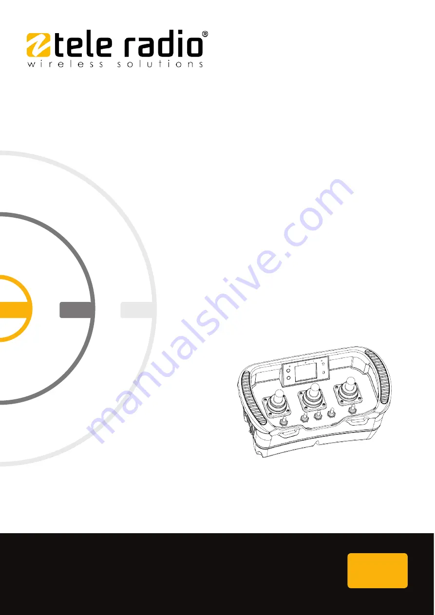
Transmitter: T24-TS01
Page 1: ...safe smart strong T24 IM PM TX103 EN v03 Language English original INSTALLATION INSTRUCTIONS Transmitter T24 TS01...
Page 2: ...IMPORTANT This product is built on base model T24 07 Tele Radio AB Datav gen 21 SE 436 32 Askim Sweden Phone 46 0 31 748 54 60...
Page 3: ...lay and display LEDS 24 5 6 Side buttons 28 CHAPTER 6 BOARD DESCRIPTION 30 6 1 Position of the printed circuit boards 30 6 2 Base board 32 6 3 Bottom board 33 6 4 Expansion boards for extra I Os 34 CH...
Page 4: ...the buzzer volume 56 9 11 Set the radio inactivity timeout 57 9 12 Select a time zone 58 9 13 Register RFID tags 59 9 14 Erase RFID tags 61 9 15 Configure repeater slot ID 62 9 16 Show the device info...
Page 5: ...ectly by radio remote control may be passed on to the end user Tele Radio AB remote controls are often built into wider applications This documentation is not intended to replace the determination of...
Page 6: ...ess the specific instructions and safety warnings of the end product manufacturer For battery precautions see 11 1 Battery precautions Tele Radio AB products are covered by a warranty against material...
Page 7: ...ion configuration and operating instructions as well as general troubleshooting Please report any error or omission in this document as well as any improvement or amendment suggestion to td tele radio...
Page 8: ...or a wide variety of applications for e g stationary or mobile equipments hydraulic machines construction forestry or agriculture equipments and more Tele Radio AB s transmitters and receivers are hig...
Page 9: ...del available Model Front Stop button on the side M12 contact on the side LEDs in handlebar Cable control Vibration motor T24 TS01 3 joysticks 5 toggle switches Standard Model Main boards Expansion bo...
Page 10: ...e belt around the waist then hook the transmitter into the waist belt straps Fig 1 Working position with a Tele Radio AB transmitter while using the Tele Radio AB waist belt NOTE Always hold the trans...
Page 11: ...e the system safely The following information is intended for use as a complement to applicable local regulations and standards IMPORTANT Tele Radio AB remote controls are often built into wider appli...
Page 12: ...eceiver must only be opened by qualified installers or authorized personnel Make sure the power supply is switched off before opening the receiver Failure to follow these instructions could result in...
Page 13: ...l Keep the safety information for future reference Always download the Installation instructions from our website www tele radio com for the latest available version l If error messages are shown it i...
Page 14: ...ith each customized system IMPORTANT Always use the Stop button in an emergency Fig 1 Example of possible locations for the stop button Here on the right side of a T24 transmitter IMPORTANT The Stop b...
Page 15: ...icable products The following receivers are designed to comply with the appointed safety requirements when used together with a T24 transmitter l R20 R21 Installation The two stop relays on the receiv...
Page 16: ...on T24 R20 T24 R21 Probability of dangerous failure per hour PFH 39 FIT PFH 28 FIT Diagnostic coverage DC 99 DC 99 Safe failure fraction SFF 99 SFF 99 Level of hardware fault tolerance HFT 1 HFT 1 Pro...
Page 17: ...a format 250 kbit s Hamming distance 6 Pairing registration Easy to pair without tools and without opening the receiver housing Configuration Display menu 4 2 Transmitter specifications 4 2 1 COMMON S...
Page 18: ...F 4 2 2 OTHER SPECI FI CATI ONS T24 TS01 Number of joysticks 3 2 axis with spring return for analog control directions2 Number of paddles Number of switches 2x maintained toggle switch 1 0 2x maintain...
Page 19: ...g XY Code XY Movement control on X Movement control on Y Movement control on Z 0x2 2 step 2x2 2 step 2 step 2x0 2 step 4x4 4 step 4 step 4x0 4 step Analog XY stepless stepless Analog Y stepless Analog...
Page 20: ...PTER 5 PRODUCT GENERAL DESCRIPTION NOTE The pictures shown in this chapter are for illustrative purposes only Depending on the configuration the actual product appearance may differ from the basic mod...
Page 21: ...24 TS01 1 Joystick 1 proportional XY 2 Joystick 2 proportional XY 3 Joystick 3 proportional XY 4 Toggle switch SW1 1 0 maintained 5 Toggle switch SW3 1 0 1 maintained 6 Toggle switch SW2 1 0 1 spring...
Page 22: ...escription 5 3 Transmitter bottom view 5 3 1 T24 TS01 1 M12 connector 2 RFID antenna not implemented 3 Belt loops 4 Battery compartments 1 and 2 5 Memory card socket not implemented 6 Stop button 7 Pr...
Page 23: ...ption 5 4 Transmitter side views 5 4 1 T24 TS01 Left side Right side 1 LCD display 2 Handlebar1 3 Joysticks 1 3 4 Toggle switches 1 5 5 Belt loops 6 SB1 7 SBX1 8 M12 connector 9 SB2 10 SB4 11 SBX2 12...
Page 24: ...Ds 1 2 are for battery 1 and battery 2 indications respectively Green means that the battery level is good while red indicates that the battery level is low When the battery LED turns red the correspo...
Page 25: ...white background and give information about an ongoing operation e g when you log in etc 5 5 3 STANDARD DI SPLAY Status and information s ymbols NOTE Applies only to TS models 1 Current channel number...
Page 26: ...session Once the transmitter has initiated a session with a receiver the display will show RF signal stength Radio frequency signal power can be indicated with three symbols depending on the signal p...
Page 27: ...nceled the Mute symbol will be shown on display CAN bus indic ation If the receiver used in the session is used as a CANbus node a CAN symbol will be shown on the display l If the CANbus communication...
Page 28: ...ctivated digital input 1 and digital input 2 respectively Analog input indic ation If analog input is active the value of the analog input will be showed as a bar graph 5 6 Side buttons The side butto...
Page 29: ...pter 5 Product general description Side button Default function in pre session session menu mode calibration mode SB3 Start Menu mode Up Calibration positive SBX2 SB4 Start Quick logout Down Calibrati...
Page 30: ...onic technicians should add and map expansion boards and inputs outputs 6 1 Position of the printed circuit boards Each board is identified by a position number When referring to a component or a conn...
Page 31: ...ircuit board for the display L Circuit board for the cap sensors on the display M Circuit board for the cap sensors on the display O RFID module P Circuit board for the cap sensors and LEDs in the han...
Page 32: ...mented 11 Connector EXPIO for Daisy chain 12 Connector for CAP2 13 Alternative connectors for CAP2 14 not implemented 15 Connector EXPIO for Daisy chain 16 not implemented 17 not implemented 18 not im...
Page 33: ...r for vibration motor 2 Connector for standard stop button 3 Connector for internal memory card not implemented 4 Connector for base board 5 Connector for battery 2 6 Connector for battery 1 7 Connect...
Page 34: ...tion Connector Pin description J4 1 Not connected J6 1 Not connected 2 S4_START DMG 2 S6_START 3 Not connected 3 Not connected 4 S4_GND 4 S6_GND J2 1 SW5 GND J3 1 SW2 GND 2 Not connected 2 Not connect...
Page 35: ...1 Not connected 2 S5_MENU 2 S5_MENU 3 Not connected 3 Not connected 4 S5_GND 4 S5_GND J6 1 Not connected J2 1 SW1 GND 2 S6_START 2 Not connected 3 Not connected 3 Not connected 4 S6_GND 4 SW3 UP 5 SW...
Page 36: ...2 green Battery 2 level is good red Battery 2 level is low must be charged red Battery 2 is charging and is not yet fully charged No battery present in battery compartment 2 Status LED green When star...
Page 37: ...n logged in until it is manually logged out More than one transmitter can be registered in the receiver but only one transmitter can be logged in at a time 8 2 General navigation The Menu system is co...
Page 38: ...be activated to prevent unauthorized personnel from operating the transmitter To activate the RFID functions contact your representative for assistance Once the RFID start up protection functions have...
Page 39: ...wing steps l Make sure that the controlled object can not cause any harm in the event of unexpected movement l Always follow local safety rules and start the equipment according to the corresponding i...
Page 40: ...3 Press the Select button to select one or more receiver s for the session The display shows Select one or more items and the list of the registered receivers Selected receivers are marked with a sign...
Page 41: ...tically be selected the next time the transmitter is started 1 Make sure that all safety measures have been followed 2 Make sure the transmitter battery is charged 3 Make sure that the Stop button is...
Page 42: ...buzzer emits a beep 11 Release both Start buttons The Status LED flashes rapidly while waiting for the receiver confirmation l If the transmitter has already been logged in to the receiver The displa...
Page 43: ...button SB4 2 Press the Stop button The display shows Logging out and Logout successful 3 Release side button SB4 The transmitter turns off 8 7 2 SOFTWARE VERSI ON SW0033 11V09 OR LOWER 1 Press and hol...
Page 44: ...tton The transmitter enters Picht Catch mode 3 Once the other transmitter has successfully logged in release the allowPitchAndCatchProcedureButton button 4 Press the Stop button 2 Log the transmitter...
Page 45: ...ensity Set the display luminosity in Buzzer Volume Set the buzzer volume level in Radio Inactivity Timeout Set the off delay in s before the transmitter automatically switches off Time Zone Select the...
Page 46: ...VERSI ON SW0033 11V10 OR HI GHER 1 Make sure that the Stop button is pressed 2 Twist and release the Stop button The initial start up logo is displayed Battery indicator s light s The display shows S...
Page 47: ...ack button will abort the procedure 7 Press the Select button to accept and move to the next digit 8 Repeat steps 6 7 until all four digits have been entered 9 Press the Back button to accept l If the...
Page 48: ...re to be successful the receiver must be powered up RISK OF UNINTENDED EQUIPMENT OPERATION Only transmitters that are intended for use should be registered in the receiver Failure to follow these inst...
Page 49: ...PIN code required 7 Navigate to the Register menu using the Up Down buttons 8 Press the Select button to enter 9 Choose a location for the receiver to be registered in using the Up Down buttons 10 Pr...
Page 50: ...D 1 is flashing slow The transmitter turns off If not successfully completed On the Receiver On the Transmitter The receiver exits registration mode LED 1 is flashing red The display shows Registratio...
Page 51: ...UTTONS 3 Enter Menu mode see 9 2 Enter Menu mode no PIN code required 4 Navigate to the Erase menu using the Up Down buttons 5 Press the Select button to enter 6 Choose the receiver s to be erased fro...
Page 52: ...ore starting the replacement The receiver will automatically be stored in the same location as in the old transmitter If this location is no longer available the replacement will fail If the transmitt...
Page 53: ...display will show the warning message Inputs have been blocked IO board 0X 0xXXXXXXXX To clear the locked inputs 1 Make sure that the Stop button is pressed 2 Twist and release the Stop button The in...
Page 54: ...e see 9 2 Enter Menu mode no PIN code required 4 Navigate to the Radio Channel menu using the Up Down buttons 5 Press the Select button to enter The display shows Range 11 26 Value XX 7 Change the cha...
Page 55: ...isplayed Battery indicator s light s The display shows Session Selection 3 Enter Menu mode see 9 2 Enter Menu mode no PIN code required 4 Navigate to the Backlight Intensity menu using the Up Down but...
Page 56: ...isplayed Battery indicator s light s The display shows Session Selection 3 Enter Menu mode see 9 2 Enter Menu mode no PIN code required 4 Navigate to the Buzzer Volume menu using the Up Down buttons 5...
Page 57: ...itial start up logo is displayed Battery indicator s light s The display shows Session Selection 3 Enter Menu mode see 9 2 Enter Menu mode no PIN code required 4 Navigate to the Radio Inactivity Timeo...
Page 58: ...t s The display shows Session Selection 3 Enter Menu mode see 9 2 Enter Menu mode no PIN code required 4 Navigate to the Time Zone menu using the Up Down buttons 5 Press the Select button to enter The...
Page 59: ...ns 5 Press the Select button to enter The display shows Select a single item and the list showing the registered RFID tags ID numbers 6 Choose a location for the RFID tag to be registered in using the...
Page 60: ...nu The next time the transmitter is started the display will shows Waiting for a valid tag to be presented Proceed with step 9 to complete the registration NOTE To check that the RFID tag has been pro...
Page 61: ...rtup Protection RFID Erase menu using the Up Down buttons 5 Press the Select button to enter The display shows Select a single item and the list showing the registered RFID tags ID numbers 6 Choose th...
Page 62: ...registered in this TX Cannot start the repeater config Register the transmitter in the receiver see 9 4 Register a transmitter in a receiver before proceeding with the configure repeater instruction...
Page 63: ...Range 0 14 Value XX 8 Change the slot ID 1 14 using the Up Down buttons 9 Press the Select button to confirm The display shows Stored in repeater The transmitter turns off Go back to step 1 and try ag...
Page 64: ...up logo is displayed Battery indicator s light s The display shows Session Selection 3 Enter Menu mode see 9 2 Enter Menu mode no PIN code required 4 Navigate to the Show device information menu usin...
Page 65: ...to be able to perform a calibration NOTE The transmitter must be registered and logged in to the receiver in order for this procedure to be successful 10 1 Enter calibration mode 1 Make sure that the...
Page 66: ...wed the output will become unusable Should that happen remove the power from the receiver without ending the session from the transmitter do not press the stop button Calibration of the output maximum...
Page 67: ...position where the valve should start to open hold and adjust the output signal with side buttons SB3 SB4 4 Move the joystick to its full position hold and adjust the output max signal with side butto...
Page 68: ...correct type l Do not short circuit disassemble deform or heat batteries l Never attempt to charge a visibly damaged or frozen battery l Do not use or charge the battery if it appears to be leaking de...
Page 69: ...multiple batteries in the same plastic bag l Do not incinerate or dispose of batteries in fire l Do not place used batteries in the household waste Dispose of used batteries in accordance with the app...
Page 70: ...hat should be charged first The LED corresponding to the battery being charged will continue to flash red while the other battery LED will remain lit red If there is any charging error during charging...
Page 71: ...M769780 or DC M769746 NOTE Electronics and batteries must be physically separated before disposal Make sure that electronics or batteries are not disposed of in household waste 11 2 1 CHARGE THE B ATT...
Page 72: ...Tele Radio AB The following are not covered by the warranty l Faults resulting from normal wear and tear l Parts of a consumable nature l Products that have been subject to unauthorized modifications...
Page 73: ...vailable on the Tele Radio AB website www tele radio com 13 1 2 WEEE DI RECTI VE This symbol means that inoperative electrical and electronic products must not be mixed with household waste The Europe...
Page 74: ...dance with the instructions may cause harmful interference to radio communications However there is no guarantee that interference will not occur in a particular installation If this equipment does ca...
Page 75: ...fin d assurer la conformit aux exigences de la IC en mati re d exposition aux RF une distance de s paration d au moins 20 cm doit tre maintenue entre l antenne de cet appareil et toute personne proxim...
Page 76: ...er 13 Regulatory information 13 3 AEC Applies to T24 01 T24 06 T24 07 T24 TS01 13 3 1 AEC STATEMENT This product is declared as compliant within Eurasian Economic Union EAC EAC declaration is availabl...
Page 77: ...DC Diagnostic Coverage FIT Failures in time 1 FIT 1 failure per 10 9 hours HFT Hardware Fault Tolerance MTTF Mean Time To Failure PFH Probability of Failure per Hour PL Performance level SFF Safety Fa...
Page 78: ...ERY PACK 70 Battery precautions 68 Handling 68 Storage 68 Boards 30 Bottom board 33 Buzzer volume 56 C Calibration mode 65 Calibration of the outputs 66 Channel number 54 CHARGERS 71 Charging temperat...
Page 79: ...Dimensions 20 Display LEDs 24 Display specifications 18 display status and information symbols 25 Disposal 69 E EIRP 17 Erase 51 Expansion boards Pinout 34 F FCC statement 74 FCC IC labels 75 Frequenc...
Page 80: ...no PIN code 46 Enter Menu mode PIN code 46 Menu protection 46 Menu navigation 37 Message types 24 N Number of channels 17 O Operating temperature 18 P PIN code 46 Position Bottom board 30 Expansion bo...
Page 81: ...18 Select a Radio frequency 54 Side buttons 28 slot ID 62 Specifications Other specifications 18 System 17 Transmitter 17 Standard display 25 Start up protection 38 Start session 41 Status and error c...
Page 82: ...Installation instructions T24 Annex B Index W Warnings restrictions 11 Installation and commission 11 Maintenance 13 Operation 12 WEEE directive 73 82 IM PM TX103 EN v03...
Page 83: ...Installation instructions T24 This page intentionally left blank IM PM TX103 EN v03 83...
Page 84: ...safe smart strong These Installation instructions are subject to change without prior notice Download the latest Installation instructions from www tele radio com...