


Managing Data
Managing Data
This section contains procedures for saving and recalling waveforms and setups, and exporting images, waveforms, and
measurements. Also procedures are included for using the clipboard and printing from your instrument. Detailed information
is available in the online help.
Saving Waveforms
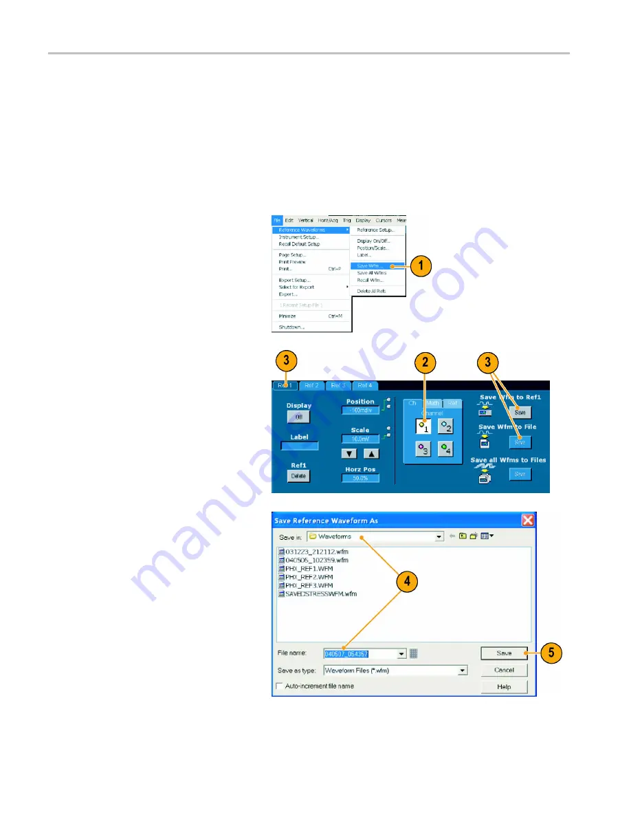
1.
To save waveforms, select
File >
Reference Waveforms > Save Wfm...
.
2.
Select the source.
3.
You can save the waveform as a
reference waveform in the instrument
memory or as a .wfm
fi
le in a Windows
directory.
To save the waveform as a reference,
select a Ref 1 through Ref 4 tab, and
click Save Wfm to Ref(n)
Save
.
To save as a .wfm
fi
le, click Save Wfm to
File
Save
, and select the location where
you want to save the waveform.
4.
If you are saving as a .wfm
fi
le, type in a
fi
le name or use the default.
5.
Click
Save
.
72
TDS6000B & TDS6000C Series Quick Start User Manual