background image

Analyze Waveform or Trace Data

Automatic Peak Markers

Automatic peak markers are on by default and assist with quickly identifying the frequency and amplitude of peaks in
the spectrum.

1.

The Reference Marker is placed on the
highest amplitude peak. It is marked with
a red R in a triangle.

2.

The automatic markers indicate
frequency and amplitude.

3.

Absolute readouts show the actual
frequency and amplitude of the
automatic markers.

4.

Delta readouts show the frequency and
amplitude of the automatic markers
relative to the reference marker.

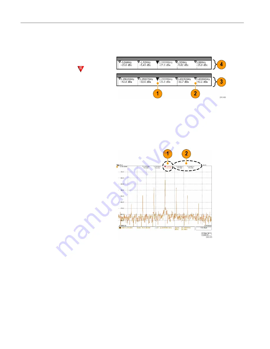
In the screen shot shown below, a marker has been placed on each of the obvious peaks in the display. The Reference
Marker is the highest peak. It is marked with the red R in a triangle, and its readout is shown in red text.

1.

Reference marker

2.

Automatic markers

Use

Threshold

and

Excursion

to de

fi

ne which peaks are marked.

The threshold is a minimum amplitude that a signal must cross to be a valid peak. If the threshold is lower, more peaks will
tend to qualify to have markers. If the threshold is higher, fewer peaks tend to qualify to have markers.

The excursion is how far a signal needs to fall in amplitude between marked peaks to be another valid peak. If the excursion
is low, more peaks will tend to qualify to have associated markers. If the excursion is high, fewer peaks will tend to qualify to
have associated markers.

118

MDO4000 Series Oscilloscopes User Manual

Summary of Contents for MDO4054-3

Page 1: ...Tektronix MDO4034 3 Manual Get Pricing Availability at ApexWaves com Call Today 1 800 915 6216 Email sales apexwaves com https www apexwaves com oscilloscopes tektronix inc mdo4000 MDO4034 3...

Page 2: ...x MDO4000 Series Mixed Domain Oscilloscopes ZZZ User Manual P071291300 071 2913 00...

Page 3: ......

Page 4: ...MDO4000 Series Mixed Domain Oscilloscopes ZZZ User Manual xx www tektronix com 071 2913 00...

Page 5: ...TEKTRONIX and TEK are registered trademarks of Tektronix Inc e Scope iView OpenChoice TekSecure and TekVPI are registered trademarks of Tektronix Inc MagniVu and Wave Inspector are trademarks of Tektr...

Page 6: ...is located Customer shall be responsible for paying all shipping charges duties taxes and any other charges for products returned to any other locations This warranty shall not apply to any defect fai...

Page 7: ...is located Customer shall be responsible for paying all shipping charges duties taxes and any other charges for products returned to any other locations This warranty shall not apply to any defect fa...

Page 8: ...Free Trial 15 Installing an Application Module 15 Changing the Language of the User Interface or Keyboard 16 Changing the Date and Time 17 Signal Path Compensation 19 Upgrading Firmware 21 Connecting...

Page 9: ...creen 108 Viewing the Trigger Frequency 109 Displaying the Frequency Domain Menu 110 Analyze Waveform or Trace Data 117 Using Markers in the Frequency Domain 117 Taking Automatic Measurements in the F...

Page 10: ...the Probe to the Oscilloscope 184 Compensating the Probe with MDO4000 Series Oscilloscopes 184 Standard Accessories 184 Optional Accessories 186 Replacing the Probe Tip 186 Specifications 187 Performa...

Page 11: ...Table of Contents iv MDO4000 Series Oscilloscopes User Manual...

Page 12: ...ounded Observe all terminal ratings To avoid fire or shock hazard observe all ratings and markings on the product Consult the product manual for further ratings information before making connections t...

Page 13: ...could result in damage to this product or other property Symbols and Terms on the Product These terms may appear on the product DANGER indicates an injury hazard immediately accessible as you read th...

Page 14: ...EN 61000 3 3 1995 Voltage changes fluctuations and flicker European contact Tektronix UK Ltd Western Peninsula Western Road Bracknell RG12 1RF United Kingdom 1 This product is intended for use in non...

Page 15: ...s listed in the Official Journal of the European Communities Low Voltage Directive 2006 95 EC EN 61010 1 2001 Safety requirements for electrical equipment for measurement control and laboratory use U...

Page 16: ...ity through conductive dust rain or snow Typical outdoor locations Pollution Degree Pollution Degree 2 as defined in IEC 61010 1 Note Rated for indoor use only Installation Overvoltage Category Descri...

Page 17: ...is product complies with the applicable European Union requirements according to Directives 2002 96 EC and 2006 66 EC on waste electrical and electronic equipment WEEE and batteries For information ab...

Page 18: ...ements Time correlated acquisition of analog digital and RF signals in a single instrument The ability to independently set acquisition parameters on the time and frequency domain channels 1 GHz and 5...

Page 19: ...Preface xii MDO4000 Series Oscilloscopes User Manual...

Page 20: ...2922 XX MDO4000 Series Oscilloscopes User Manual Russian Option L10 071 2923 XX MDO4000 Series Oscilloscopes Documentation Browser CD Electronic versions of documents including the Programmer Manual...

Page 21: ...016 2030 XX Optional accessories Accessory Description Tektronix part number Aerospace serial triggering and analysis application module This module enables triggering on MIL STD 1553 serial buses Al...

Page 22: ...tools bus views and decode tables with time stamp information DPO4ENET Limit and mask test application module This module supports limit testing and testing on telecom standard masks or custom masks D...

Page 23: ...pes 077 0585 XX MSO4000B DPO4000B and MDO4000 Series Application Module Installation Instructions Describes how to install application modules on your oscilloscope 071 2136 XX English Option L0 071 26...

Page 24: ...of feet to front of knobs 147 mm 5 8 in Depth from back of feet to front of front cover 155 mm 6 1 in MDO4000 Series Temperature Operating 0 C to 50 C 32 F to 122 F Non operating 20 C to 60 C 4 F to...

Page 25: ...z and 45 MHz Derate at 14 dB decade between 45 MHz and 450 MHz Above 450 MHz 5 VRMS Acquisition System 50 The maximum input voltage at the BNC 5 VRMS with peaks 20 V DF 6 25 P6616 Digital Probe Inputs...

Page 26: ...scilloscope and probes as often as operating conditions require To clean the exterior surface perform the following steps 1 Remove loose dust on the outside of the oscilloscope and probes with a lint...

Page 27: ...ope to optimize the signal input path This provides AC compensation across the frequency band 3 TPA BNC Adapter The TPA BNC Adapter allows you to use TEKPROBE II probe capabilities such as providing p...

Page 28: ...Installation Securing the Oscilloscope 1 Use a standard laptop computer style security lock to secure your oscilloscope to your location MDO4000 Series Oscilloscopes User Manual 9...

Page 29: ...om the instrument Grounding the oscilloscope is necessary for safety and to take accurate measurements The oscilloscope needs to share the same ground as any circuits that you are testing If you are w...

Page 30: ...power cord Functional Check Perform this quick functional check to verify that your oscilloscope is operating correctly 1 Connect the oscilloscope power cable as described in Powering On the Oscillosc...

Page 31: ...uation have the instrument serviced by qualified service personnel Compensating a TPP0500 or TPP1000 Passive Voltage Probe The MDO4000 Series oscilloscopes can automatically compensate TPP0500 and TPP...

Page 32: ...mp terminals 4 Push a front panel button for an input channel connected to the probe you wish to compensate 1 2 3 or 4 5 Notice on the lower menu that the oscilloscope has automatically set the probe...

Page 33: ...e Aux In channel NOTE A factory calibration will delete all stored compensation values NOTE A probe compensation failure is most likely due to intermittent connection of the probe tip or ground connec...

Page 34: ...illoscope The trial period begins when you power on the oscilloscope for the first time After 30 days you must purchase the module if you want to continue using the application To see the date when yo...

Page 35: ...ect Config Push the lower menu Application Module Licenses button and the appropriate side menu buttons to transfer the license from the module to the oscilloscope or from the oscilloscope to the modu...

Page 36: ...side menu and turn multipurpose knob a to select the desired language version of keyboard to use USB Keyboard English 7 If you choose to use an English user interface be sure that the plastic front p...

Page 37: ...ity Page Config Language Set Date Time TekSecure Erase Memory About 5 Push the side bezel buttons and turn both multipurpose knobs a and b to set the time and date values Display Date Time On Off Hour...

Page 38: ...e to do so may result in the instrument not meeting warranted performance levels at those volts div settings Signal Path Compensation for Time and Frequency Domains To compensate the signal path 1 War...

Page 39: ...cilloscope using external sources Contact your Tektronix field office or representative for assistance with factory calibration NOTE Signal Path Compensation does not include calibration to the probe...

Page 40: ...te RF Signal Path Upgrading Firmware To upgrade the firmware of the oscilloscope 1 Open up a Web browser and go to www tektronix com software Proceed to the software finder Download the latest firmwar...

Page 41: ...nstrument does not install the firmware rerun the procedure If the problem continues try a different model of USB flash or hard drive Finally if needed contact qualified service personnel NOTE Do not...

Page 42: ...ipurpose knob a and select Config Config 10 Push About The oscilloscope displays the firmware version number Utility Page Config Language English Set Date Time TekSecure Erase Memory About 11 Confirm...

Page 43: ...ge that runs on your PC such as Microsoft Excel National Instruments LabVIEW Tektronix OpenChoice Desktop software or a program of your own creation You can use a common communications connection such...

Page 44: ...Connect to Computer on the side bezel menu 7 To use Ethernet push the Ethernet LXI lower bezel button Use the side bezel buttons to adjust your network settings as needed For more information see the...

Page 45: ...vice port is the correct USB port for computer connectivity Use the rear and front panel USB 2 0 host ports to connect your oscilloscope to USB flash drives Use the USB Device port to connect your osc...

Page 46: ...ndicator turns green for good status and red if the device detects a fault Ethernet LXI LAN Status 7 Push LAN Settings to display the network parameters configured on your oscilloscope LAN Settings 8...

Page 47: ...browser Change e Scope Password a Enabled more 2 of 2 14 Start your browser on your remote computer In the browser address line enter the host name a dot and the domain name together Alternatively jus...

Page 48: ...ides two way communication over an Internet Protocol based computer network You can use your oscilloscope s socket server feature to let your oscilloscope communicate with a remote terminal device or...

Page 49: ...Enabled Enabled Disabled 7 Choose whether the protocol should be None or Terminal A communication session run by a human at a keyboard typically uses a terminal protocol An automated session might ha...

Page 50: ...typing in an open command with the oscilloscope s LAN address and port You can obtain the LAN address by pushing the Ethernet LXI bottom menu item and the resulting LAN Settings side menu item to vie...

Page 51: ...s plugged in while the oscilloscope is powered on You can use the keyboard to quickly create names or labels You can bring up the Label menu through the lower bezel label button of the Channel or Bus...

Page 52: ...or the functions that you use most often Use the menu buttons to access more specialized functions Overview 1 Frequency domain display 2 Time domain display 3 Traditional oscilloscope front panel cont...

Page 53: ...elect a menu item If a pop out menu appears turn multipurpose knob a to select the desired choice If a pop up menu appears push the button again to select the desired choice 3 Push a side bezel button...

Page 54: ...u Buttons Use the menu buttons to perform many functions in the oscilloscope 1 Measure Push to perform automated measurements on waveforms 2 Search Push to perform an automated search through an acqui...

Page 55: ...and to display or remove the corresponding waveform from the display 10 B1 B2 B3 or B4 Push to define and display a bus if you have the appropriate module application keys DPO4AERO supports MIL STD 1...

Page 56: ...val of the math waveform or trace from the display Using Spectral Analysis Controls These buttons configure the acquisition and display of the RF input 1 RF Push to bring up the frequency domain displ...

Page 57: ...ggle between making coarse and fine adjustments with the vertical and horizontal position knobs the trigger level knob and many operations of multipurpose knobs a and b 4 Turn the lower multipurpose k...

Page 58: ...urn to control the zoom factor Turning it clockwise zooms in further Turning it counterclockwise zooms out 10 Play pause button Push to start or stop the automatic panning of a waveform Control the sp...

Page 59: ...nding waveform Push Fine to make smaller adjustments 22 1 2 3 4 Push to display or remove the corresponding waveform from the display and access the vertical menu 23 Vertical Scale Turn to adjust the...

Page 60: ...rrent save parameters as defined in the Save Recall menu 28 Default Setup Push to perform an immediate restore of the oscilloscope to the default settings 29 D15 D0 Push to display or remove the digit...

Page 61: ...ule area when menus are turned off 1 The acquisition readout shows when an acquisition is running stopped or when acquisition preview is in effect Icons are Run Acquisitions enabled Stop Acquisitions...

Page 62: ...waveform record The line color corresponds to the selected waveform color The brackets show the part of the record currently displayed on the screen 5 The trigger status readout shows trigger status...

Page 63: ...shows on the top line the horizontal scale adjust with the Horizontal Scale knob With Delay Mode on the bottom line shows the time from the T symbol to the expansion point icon adjust with the Horizon...

Page 64: ...the math and reference waveforms 14 The channel readout shows the channel scale factor per division coupling invert and bandwidth status Adjust with the Vertical Scale knob and in the channel 1 2 3 or...

Page 65: ...hows the bus number and bus type Identifying Items in the Frequency Domain Display Activate the frequency domain display by pressing the front panel RF button 1 Vertical graticule labels 2 Start frequ...

Page 66: ...be Interface 3 RF Input Connector 4 PROBE COMP Square wave signal source to compensate or calibrate probes Output voltage 0 2 5 V amplitude 1 behind 1 k 2 Frequency 1 kHz 5 Ground 6 Application Module...

Page 67: ...el for Vout HI is 2 5 V open circuit 1 0 V into a 50 load to ground The logic level for Vout LO is 0 7 V into a load of 4 mA 0 25 V into a 50 load to ground 2 EXT REF IN You can connect an external cl...

Page 68: ...es This lets you run your GPIB software applications on USB hardware Also use the USB port to connect a PictBridge compatible printer to the oscilloscope 6 Host Use the USB 2 0 high speed host ports t...

Page 69: ...up your instrument to acquire signals using the analog channels 1 Connect the TPP0500 TPP1000 or VPI probe to the input signal source 2 Select the input channel by pushing the front panel buttons NOTE...

Page 70: ...Quick Tip Use the zoom feature to see multiple cycles of your signal in the upper part and a single cycle in the lower part of the display See page 144 Using Wave Inspector to Manage Long Record Leng...

Page 71: ...the label after you insert it if necessary 5 Push Insert Preset Label to add the label Insert Preset Label If you are using a USB keyboard use the arrow keys to position the insertion point and edit t...

Page 72: ...oper character to use You can use the lower bezel buttons to edit the label as needed Enter Character Back Space Delete Clear 9 Continue scrolling and pushing Select until you have entered all the des...

Page 73: ...oset works with both the analog and digital channels 1 To autoset an analog channel connect the analog probe and then select the input channel See page 50 Setting Up Analog Channels To autoset a digit...

Page 74: ...ope automatically sets the trigger type to video and makes other adjustments to display a stable video signal Acquisition Concepts Before a signal can be displayed it must pass through the input chann...

Page 75: ...cord length The number of samples required to fill a waveform record Set this by pushing the Acquire button and using the resulting lower and side bezel menus Trigger point The zero time reference in...

Page 76: ...sition interval This mode also only works with real time noninterpolated sampling Hi Res provides a higher resolution lower bandwidth waveform Envelope mode finds the highest and lowest record points...

Page 77: ...e discarded at lower sweep speeds Therefore these modes only work when the current sample rate is less than the maximum possible sample rate As soon as the oscilloscope starts to acquire at the maximu...

Page 78: ...e trigger event by a significant interval of time For example you can trigger on a sync pulse that occurs once every 10 ms and then look at high speed signal characteristics that occur 6 ms after the...

Page 79: ...Ray DPO4AUTOMAX application module I2C and SPI DPO4EMBD application module MIL STD 1553 DPO4AERO application module Parallel MDO4000 Series oscilloscope RS 232 RS 422 RS 485 and UART DPO4COMP applicat...

Page 80: ...nditions refer to Triggering on Buses See page 86 Triggering on Buses To set up bus parameters 1 Push B1 B2 B3 or B4 to bring up the lower bezel bus menu 2 Push Bus Turn multipurpose knob a to scroll...

Page 81: ...r digital channel as the source for the bit Define Bits a Bit 15 b D15 4 Push Thresholds Bus B1 Parallel Define Inputs Thresholds B1 Label Parallel Bus Display Event Table You can set the threshold fo...

Page 82: ...mat Bus and Wave forms Hex Binary ASCII 7 Push Event Table and select On to display a list of bus packets with timestamps Event Table On Off Save Event Table For a clocked parallel bus the table lists...

Page 83: ...nt tables display one line for each 7 or 8 bit byte when Packets are set to Off RS 232 event tables display one line for each packet when Packets are set to On Other buses display one word frame or pa...

Page 84: ...loscope displays 7 bit addresses as eight bits where the eighth bit LSB is the R W bit It displays 10 bit addresses as 11 bits where the third bit is the R W bit If you select No the oscilloscope disp...

Page 85: ...Low more 1 0f 2 5 Use multipurpose knob a to set the number of bits of the SPI Word Size Word Size a 8 bits 6 Push either side bezel button to set the bit order of the SPI bus Bit Order MS First Bit...

Page 86: ...ding displays a stream of bytes You can organize the stream into packets with an end of packet character If you defined an end of packet character to use for RS 232 decoding the stream of bytes will b...

Page 87: ...an set the bit rate to a specific value To do so select Custom and then turn multipurpose knob b to set the bit rate from 10 000 to 1 000 000 LIN Bus To acquire data from a LIN bus you need to also se...

Page 88: ...the bit rate from 800 bps to 100 000 bps Bit Rate a 19 2K bps 7 Push LIN Standard and turn multipurpose knob a to select the appropriate standard LIN Standard v1 x 8 Push Include Parity Bits with Id...

Page 89: ...of the word select clock Left Justified LJ 5 Select Right Justified to trigger on an I2S stream where the data lines up with the right edge of the word select clock Right Justified RJ 6 Select TDM to...

Page 90: ...Thresholds Bus Display and Event Table menus operate similarly to the other serial buses 3 Push IPv4 to decide whether or not to decode and trigger on Internet Protocol version 4 signals MIL STD 1553...

Page 91: ...er are to the right I2C and CAN buses transmit the MSB most significant bit first SPI buses do not specify a bit order RS 232 and LIN buses transmit the LSB least significant bit first NOTE The oscill...

Page 92: ...round You can connect a separate lead for each channel or a common ground lead for each group of 8 wires 3 If needed connect the appropriate grabber for each probe to the probe tip 4 Connect each prob...

Page 93: ...lution See page 75 When and Why to Turn On MagniVu 11 Push the lower bezel Height button repeatedly to set the signal height You only need to do this once to set the height for all of the digital chan...

Page 94: ...and you are looking somewhere other than the trigger point then the digital signal may be off screen In most of these cases you can find the digital record by looking for the digital signal in the up...

Page 95: ...recise frequency at the center of the display In many applications it is a carrier frequency 2 The span is the range of frequencies you can observe around the center frequency To define the center fre...

Page 96: ...rpose knob b or the keypad to enter the desired span If you use the keypad you can also use the resulting side menu choices to enter units Span a 3 00 GHz 4 Push Start to set the lowest frequency to c...

Page 97: ...our application requires a different unit of measurement than that being currently displayed Vertical Units dBm 5 Push Auto Level to direct the oscilloscope to automatically calculate and set the refe...

Page 98: ...wn resolution bandwidth RBW Mode Auto Manual 3 To manually adjust the RBW push RBW and turn multipurpose knob a RBW a 600 kHz Auto 4 Push Span RBW and turn multipurpose knob a to set the span RBW rati...

Page 99: ...display Triggered display Trigger Modes The trigger mode determines how the instrument behaves in the absence of a trigger event Normal trigger mode enables the instrument to acquire a waveform only...

Page 100: ...remains disabled during the holdoff period that follows each acquisition Holdoffs Trigger Coupling Trigger coupling determines what part of the signal is passed to the trigger circuit Edge and Sequen...

Page 101: ...ou may uncover information that helps you find the source of the glitch Alternatively to see what is happening in your system as a result of the trigger event make the posttrigger period large enough...

Page 102: ...pplication module Using the bus trigger on other buses requires use of a DPO4AERO DPO4AUDIO DPO4AUTO DPO4AUTOMAX DPO4COMP DPO4EMBD DPO4ENET or DPO4USB application module Bus 3 Turn multipurpose knob a...

Page 103: ...fore triggering and displaying the waveform Events After the A Event occurs the trigger system looks for a specified number of B Events before triggering and displaying the waveform Pulse Width Trigge...

Page 104: ...formance is achieved by using only analog channels or only digital channels Setup and Hold Trigger when a logic data input changes state inside of the setup or hold time relative to a clock edge Setup...

Page 105: ...a DPO4AUTOMAX module FlexRay requires a DPO4AUTOMAX module Audio requires a DPO4AUDIO module USB requires a DPO4USB module Ethernet requires a DPO4ENET module MIL STD 1553 requires a DPO4AERO module...

Page 106: ...s Data push the lower bezel Address button to access the I2C Address side bezel menu Push the side bezel Addressing Mode button and select 7 bit or 10 bit Push the side bezel Address button Enter the...

Page 107: ...e Remote Frame Error Frame or Overload Frame If you have made a Trigger On selection of Identifier push the lower bezel Identifier button and select a Format They push the Identifier side bezel button...

Page 108: ...ou are setting up a MIL STD 1553 trigger and have made a Trigger On selection of Data push the lower bezel Data button to enter specific Data values and the Parity value If you are setting up a MIL ST...

Page 109: ...hes the identifier and data selected by the user with the data starting at the first byte No rolling window is used For FlexRay and Ethernet triggering occurs when the user selected data input matches...

Page 110: ...orm A and B triggers can and typically do have separate sources Use the Edge trigger menu to set up the A trigger first Then to use the B trigger 1 Push Trigger Menu 2 Push Type 3 Turn multipurpose kn...

Page 111: ...B edge after the trigger delay time Trigger on B Events The A trigger arms the instrument Posttrigger acquisition starts on the nth B event Quick Tips B trigger delay time and horizontal position are...

Page 112: ...GHz to 4 5 GHz and 3 5 GHz to 6 0 GHz The MDO4000 Series provides RF Power as a source for Edge triggering This enables your oscilloscope to trigger as the RF power envelope passes through a specific...

Page 113: ...lt the RF power threshold will impact the amount of trigger delay and the apparent width of the pulse For example when the trigger level is at 10 dBm the amount of delay will be approximately 500 ns T...

Page 114: ...edge trigger power level is now raised to 10 dBm The trigger indication is now delayed approximately 500 ns from the start of the burst This is due to the power detector response discussed previously...

Page 115: ...m from the display push the corresponding front panel channel button or the D15 D0 button You can use the channel as a trigger source whether or not it is displayed Setting the Display Style and Persi...

Page 116: ...ce to Off to display the display persistence Persis tence On Off 5 Push Persist Time and turn multipurpose knob a to have waveform data remain on screen for a user specified amount of time Persist Tim...

Page 117: ...ently appearing signal anomalies such as glitches Infinite persistence continuously accumulates record points until you change one of the acquisition display settings Use infinite persistence for disp...

Page 118: ...ips You can display IRE and mV graticules To do this set the trigger type to video and set the vertical scale to 114 mV division The 114 mV division selection is available in the coarse vertical scale...

Page 119: ...d Low Backlight Intensity High Med Low Setting Waveform Intensity 1 Push the front panel Intensity button This will bring up the intensity readout on the display 2 Rotate multipurpose knob a to select...

Page 120: ...age 144 Using Wave Inspector to Manage Long Record Length Waveforms Original waveform Scaled horizontally Positioned horizontally Use the vertical controls to select waveforms adjust the waveform vert...

Page 121: ...channel menu button 1 2 3 or 4 to bring up the vertical menu for the designated waveform The vertical menu only affects the selected waveform Pushing a channel button will also select or cancel that...

Page 122: ...u can push this button to instruct the oscilloscope to perform an AC calibration on the entire signal path from the probe tip to the specific oscilloscope channel This can result in a flatter frequenc...

Page 123: ...rpose knob a to set the Amps Volts ratio Attenuation to match the probe If you are measuring current by probing the voltage drop across a resistor set Measure Current to Yes Push A V ratio side bezel...

Page 124: ...be II or the TekVPI interface the oscilloscope sets the channel sensitivity coupling and termination resistance automatically to match the probe requirements Tek Probe II probes require use of the TPA...

Page 125: ...nt panel bus button to select that bus 2 Turn multipurpose knob a to adjust the vertical position of the selected bus Labeling bus signals To label a bus do the following steps 1 Push the appropriate...

Page 126: ...you stop rotating the knob 6 To change the scale height of the digital channels push the lower menu Height button NOTE The S Small selection will display each waveform at 0 2 divisions tall The M Medi...

Page 127: ...d in green Logic low levels are displayed in blue When a single transition occurs during the time represented by one pixel column the transition edge is displayed in gray When multiple transitions occ...

Page 128: ...Turn multipurpose knob a to scroll through the list of letters numbers and other characters to select each desired character Alternatively use a USB keyboard to type in characters See page 32 Connecti...

Page 129: ...ush RF to bring up the bottom bezel frequency domain menu 2 Push Spectrum Traces to bring up the side menu of four different spectrum trace types that the MDO4000 can display Spectrum Traces RF Versus...

Page 130: ...to set the number of waveforms to include in each average Average 16 On Off 4 Set Max Hold to On to display the max hold trace Max Hold On Off 5 Set Min Hold to On to display the min hold trace Min Ho...

Page 131: ...s that the minimum trace is currently selected Detection Types The MDO4000 calculates FFTs with a 1 000 to 2 000 000 point output depending on the acquisition settings It then reduces that FFT output...

Page 132: ...RF Versus Time Traces from the RF Menu to bring up the related side menu RF Versus Time Traces 2 Set Amplitude to On to display the amplitude versus time trace Amplitude On Off 3 Set Frequency to On...

Page 133: ...s Time trace The instantaneous phase of the input relative to the center frequency The vertical axis is phase with wrapping at roughly 180 All of these traces are derived from the time domain IQ data...

Page 134: ...litude Spectrogram slices are generated by taking each spectrum and flipping it on its edge so that it is one pixel row tall and then assigning colors to each pixel based on the amplitude at that freq...

Page 135: ...free run mode the MDO4000 acquires spectrums as fast as possible To use the spectrogram triggered and free run feature push Spectrom from the RF Menu to toggle between Triggered and Free Run Remember...

Page 136: ...ied number of Peak Markers identified in this control then only the specified number of highest amplitude peaks will be marked Peak Markers a 5 On Off 3 Push To Centerto set the center frequency to th...

Page 137: ...of the obvious peaks in the display The Reference Marker is the highest peak It is marked with the red R in a triangle and its readout is shown in red text 1 Reference marker 2 Automatic markers Use T...

Page 138: ...e knob a and can be moved to any location you desire This enables easy measurement of any part of the spectrum as well as delta measurements to any part of the spectrum This also lets you measure non...

Page 139: ...main power for the upper and lower halves of each adjacent channel Adjacent Channel Power Ratio Occupied bandwidth The bandwidth that contains the specified of power within the analysis bandwidth Occ...

Page 140: ...ve Measurement turn multipurpose knob a to select the specific measurement and push OK Remove Measurement on the side bezel menu Quick Tips To remove all measurements select Remove All Measurements A...

Page 141: ...ng edge of the first pulse in the waveform or gated region to fall from the high reference value default 90 to the low reference value default 10 of the final value Delay The time between the mid refe...

Page 142: ...d region Min The most negative peak voltage Min is measured over the entire waveform or gated region High This value is used as 100 whenever high reference mid reference or low reference values are ne...

Page 143: ...the entire waveform or gated region Cycle RMS The true Root Mean Square voltage over the first cycle in the waveform or the first cycle in the gated region Miscellaneous measurements Measurement Descr...

Page 144: ...eak to peak Displays the peak to peak value of the histogram Vertical histograms display the voltage of the highest nonzero bin minus the voltage of the lowest nonzero bin Horizontal histograms displa...

Page 145: ...a certain portion of a waveform To use 1 Push Measure 2 Push More as many times as needed to select Gating from the resulting pop up menu Add Mea surement Remove Measure ment Indicators Waveform His...

Page 146: ...tistics on or off and how many samples to use for mean and standard deviation calculations Measure ment Sta tistics On Off Mean Std Dev Samples a 32 Reset Statistics Snapshot To see all the single sou...

Page 147: ...12 2 s 103 7 s 936 5 s 1 452 s 33 23 7 143 9 200 V 10 40 V 16 80 V 5 396 V 7 769 V 21 58 mVs 1 2 Freq Width Fall Duty Over Low Min Pk Pk CycleMean CycleRMS CycleArea Edges Pulses 3 203 kHz 208 5 s 1 1...

Page 148: ...Ref a 90 0 Use Mid reference primarily for measurements between edges such as pulse widths Mid Ref 50 0 50 0 Low Ref 10 0 Set to Defaults Taking Manual Measurements with Cursors Cursors are on screen...

Page 149: ...tween the cursors 3 Push Fine to toggle between a coarse and a fine adjustment for multipurpose knobs a and b Pushing Fine also changes the sensitivity of other knobs as well 4 Push and hold Cursors t...

Page 150: ...reen by pushing one or more of the channel 1 through 4 buttons or by pushing the D15 D0 button 10 Push and hold Cursors to display the cursor menu again 11 Push Source from the lower bezel menu A pop...

Page 151: ...en a bus is selected the readout shows the decoded bus data in the format you have selected from the choices in the bus menu When a digital channel is selected the cursors show the values of all displ...

Page 152: ...ors in the upper graticule YT Setting Up a Histogram You can display a vertical voltage or horizontal time histogram Use histogram measurements to get statistical measurement data for a section of a w...

Page 153: ...multipurpose knobs a and b to set the T top and B bottom boundaries of the histogram box Vert Limits T a 584ns B b 760ns 8 Push more 1 of 2 more 1 of 2 9 Push the Display side bezel button and select...

Page 154: ...e steps 1 Push the Waveform Histograms lower bezel button Add Mea surement Remove Measure ment Indicators Wave form His tograms More Bring Cursors On Screen 2 Push the more 1 of 2 side bezel button mo...

Page 155: ...l histograms to measure signal noise Using Math Waveforms Create math waveforms to support the analysis of your channel and reference waveforms By combining and transforming source waveforms and other...

Page 156: ...heir horizontal scale and position from the sources in their math expressions Adjusting these controls for the source waveforms also adjusts the math waveform You can zoom in on math waveforms using t...

Page 157: ...T Source 1 4 Push the side bezel Vertical Scale button repeatedly to select either Linear RMS or dBV RMS Vertical Units Linear RMS 5 Push the side bezel Window button repeatedly to select the desired...

Page 158: ...Window Rectangular This is the best type of window for resolving frequencies that are very close to the same value but worst for accurately measuring the amplitude of those frequencies It is the best...

Page 159: ...or measuring the amplitude of frequencies but worst at resolving frequencies Use Blackman Harris for measuring predominantly single frequency waveforms to look for higher order harmonics Using Advance...

Page 160: ...Turn multipurpose knob a to select 7 Push OK Accept Using Spectrum Math The spectrum math feature lets you create a math waveform by adding or subtracting frequency traces 1 Push Math 2 Push Spectrum...

Page 161: ...s Create and store a reference waveform or trace For example you might do this to set up a standard against which to compare other waveforms To use the reference waveforms or traces NOTE 10 M and 20 M...

Page 162: ...ay all the reference waveforms at the same time Push the appropriate screen button to select a particular reference waveform Removing Reference Waveforms from the Display To remove a reference wavefor...

Page 163: ...rn the Zoom knob To scroll through a zoomed waveform turn the Pan knob The Pan Zoom Control consists of 1 An outer pan knob 2 An inner zoom knob Zooming a Waveform To use zoom 1 Rotate the inner knob...

Page 164: ...ugh the waveform To use pan 1 Rotate the pan outer knob of the pan zoom controls to pan the waveform Turn the knob clockwise to pan forward Turn it counterclockwise to pan backwards The further you tu...

Page 165: ...he waveform automatically if they meet some special criteria or you can manually mark each item of interest You can use arrow keys to jump from mark to mark area of interest to area of interest You ca...

Page 166: ...o jump to the mark you want to clear To remove the current center positioned mark push Set Clear It works on both manually and automatically created marks To automatically set and clear delete search...

Page 167: ...The Wave Inspector includes the following search capabilities Search Description Edge Searches for edges rising or falling with a user specified threshold level Pulse Width Searches for positive or ne...

Page 168: ...turned on you can also search for Q Tag Control Information MIL STD 1553 Search for Sync Command Status Data Time RT IMG Error Auto magnify As you adjust the horizontal scale control to faster time di...

Page 169: ...l any activity in the frequency domain display Time Correlated Multi Domain Display A single trigger event coordinates acquisition across all analog digital and RF channels This enables a time correla...

Page 170: ...series is its ability to move spectrum time through analog time This allows you to see how the spectrum changes over time and how it changes relative to other analog signals digital signals or serial...

Page 171: ...me goes back to the middle of the RF acquisition time Keep rotating the pan control counter clockwise and move the RF acquisition time and spectrum time together toward the left of the display When th...

Page 172: ...e the zoom controls to look more closely into analog time and the time correlated multi domain display With zoom on the oscilloscope centers spectrum time in the center of the zoomed view of the time...

Page 173: ...side the RF acquisition time Limit and Mask Testing Monitor an active input signal against a mask and output pass or fail results by judging whether the input signal is within the bounds of the mask T...

Page 174: ...t test Source Channel a 1 9 Push Horizontal Limit to set the mask horizontal limits The units are referenced to graticule divisions where one major division contains 1 000 milli divisions mdiv Horizon...

Page 175: ...ask via a remote interface Create a custom mask by editing a standard mask 1 Push the front panel Test button 2 Push the lower bezel menu Application item Turn multipurpose knob a to select Limit Mask...

Page 176: ...ve value will bring the upper and lower segments together NOTE For more on editing capabilities see the Create a custom mask from a text file section or the Create a mask via a remote interface sectio...

Page 177: ...0000E 3 13 4214E 9 200 0000E 3 13 4214E 9 500 0000E 3 11 6780E 9 800 0000E 3 7 2750E 9 900 0000E 3 2 8720E 9 800 0000E 3 1 1286E 9 500 0000E 3 1 1286E 9 200 0000E 3 7 5000E 9 100 0000E 3 MASK USER SEG...

Page 178: ...ed polarity for the remained of the test Run the Test and View the Results 1 Push the lower bezel Run Test item to start and stop the test Application Limit Mask Test Set Up Mask On Select Mask Standa...

Page 179: ...se knob a to select Power Analysis 3 Push Analysis Applica tion Analysis None 4 Use the side bezel buttons to select the desired analysis function Choose among power quality switching loss harmonics r...

Page 180: ...storage locations Use multipurpose knob a to scroll through the list of files Use the Select front panel button to open and close folders Naming your file The oscilloscope gives all files it creates a...

Page 181: ...e that file is named tek00000 The next time you save the same type of file the file will be named tek00001 Editing file directory reference waveform or instrument setup names Give files descriptive na...

Page 182: ...Saving a Screen Image A screen image consists of a graphical image of the oscilloscope screen This is different from waveform data which consists of numeric values for each point in the waveform To s...

Page 183: ...ng a Hard Copy See page 171 Printing a Hard Copy Saving and Recalling Waveform and Trace Data Waveform and trace data consists of the numeric values for each point in the waveform or trace It copies t...

Page 184: ...lay data or as baseband I and Q data TIQ files Use the I and Q data with Tektronix SignalVu Vector Signal Analysis software 4 Rotate multipurpose knob b and select the location to save the waveform or...

Page 185: ...st sized file Use this format if you intend to recall an analog waveform or RF trace to reference memory for viewing or measuring Spreadsheet file format csv Sets the oscilloscope to save data as a co...

Page 186: ...e displayed again with another push of the button NOTE 10 M and 20 M reference waveforms are volatile and not saved when the oscilloscope power is turned off To keep these waveforms save them to exter...

Page 187: ...on To save setup information to a USB or network drive push the To File button To Setup 1 To Setup 2 more 4 If you are saving information to a USB or network drive turn multipurpose knob a to scroll t...

Page 188: ...tton For example if you have defined the save operation to save waveform data to a USB flash drive then each push of the Save button will save current waveform data to the defined USB flash drive 1 To...

Page 189: ...a new folder Delete a highlighted directory or file Copy a highlighted drive directory or file Paste a previously copied drive directory or file Mount or unmount a networked drive Rename a highlighted...

Page 190: ...displays s as you type the password They are erased from the screen after OK Accept is pushed NOTE Ensure that file sharing is enabled for the network location 4 Push OK Accept NOTE To unmount a netwo...

Page 191: ...ictBridge Printer Settings Turn multipurpose knob a to scroll through the list of available printers Push Select to choose the desired printer To add a non PictBridge USB printer to the list plug the...

Page 192: ...er off Printing to a PictBridge Printer To set up the oscilloscope to print to a PictBridge printer 1 Push Utility 2 Push Utility Page Utility Page 3 Turn multipurpose knob a and select I O I O 4 Push...

Page 193: ...idge Printer Disabled Off bus Printing Over Ethernet To set up the oscilloscope to print over Ethernet 1 Connect an Ethernet cable to the rear panel Ethernet port 2 Push Utility 3 Push Utility Page Ut...

Page 194: ...u are using a USB keyboard use the arrow keys to position the insertion point and type in the printer name See page 32 Connecting a USB Keyboard to Your Oscilloscope ABCDEFGHIJKLMNOPQRSTUVWXYZ abcdefg...

Page 195: ...Select or Enter Character as often as needed to enter the name 14 When done push OK Accept NOTE If you have multiple printers connected to the oscilloscope at the same time the oscilloscope will prin...

Page 196: ...ith null values Replaces the current front panel setup and all stored setups with the default setup Displays a confirmation or warning message depending on whether the verification is successful or un...

Page 197: ...Save and Recall Information 6 Power off the oscilloscope and then power it back on to complete the process 178 MDO4000 Series Oscilloscopes User Manual...

Page 198: ...ggering and Analysis Module adds triggering and analysis on byte or packet level information in RS 232 RS 422 RS 485 and UART buses and analytical tools to help you efficiently analyze your serial bus...

Page 199: ...BNC terminated DC Gain Accuracy For 1 M 50 path checked direct and for 250 K path checked indirect For 50 path 2 0 derated at 0 100 C above 30 C 1 mV Div setting 1 5 derated at 0 100 C above 30 C 3 0...

Page 200: ...V Instrument Bandwidth selection 1 M 50 Full Bandwidth 300 V 8 0 of Volts div setting 75 V 6 0 of Volts div setting 250 MHz bandwidth limit 100 V 5 0 of Volts div setting 50 V 4 0 of Volts div setting...

Page 201: ...response Delta time measurement accuracy The term under the square root sign is the stability and is due to TIE Time Interval Error The errors due to this term occur throughout a single shot measurem...

Page 202: ...requencies 48 dB from reference level 1 GHz to 2 GHz oscilloscope input frequencies Table 5 Input Output port specifications Characteristic Description Selectable output Trigger Out or Reference Clock...

Page 203: ...trations below Compensating the Probe with MDO4000 Series Oscilloscopes For information on compensating the probe refer to the related section earlier in this manual See page 12 Compensating a TPP0500...

Page 204: ...nix part number 206 0610 XX Pogo tip This spring loaded tip allows compliant testing of circuit boards The probe tip retracts slightly when pressure is applied to it and then springs back into place R...

Page 205: ...6 in 196 3198 xx Ground Lead Alligator 12 in 196 3512 xx MicroCKT Test Tip 206 0569 xx Circuit Board Test Point PCB Adapter 016 2016 xx Compact Probe Tip Ckt Board Test Point 131 4210 xx Wire spool 32...

Page 206: ...500 MHz 1 GHz System rise time typical 350 ps 700 ps System input capacitance Rigid tip 3 9 pF 0 3 pf Pogo pin tip 5 1 pf 0 5 pf System attenuation accuracy 10 1 2 2 Probe series resistance DC 9 75 M...

Page 207: ...es Low Voltage Directive 2006 95 EC EN61010 031 2002 Category Examples of Products in this Category CAT III Distribution level mains fixed installation CAT II Local level mains appliances portable equ...

Page 208: ...ire or shock hazard observe all ratings and markings on the product Consult the product manual for further ratings information before making connections to the product Avoid Electric Shock When using...

Page 209: ...Appendix B TPP0500 and TPP1000 500 MHz and 1 GHz 10X Passive Probes Information Symbols on the Product These symbols may appear on the product 190 MDO4000 Series Oscilloscopes User Manual...

Page 210: ...d GROUP 2 The first lead in each set is identified by blue insulation and the remaining seven leads are gray All leads include a ground connection at the tip You can connect the probe leads separately...

Page 211: ...annels Channel label To set and view bus characteristics do the following Push the B1 to B4 buttons The setup screens allow you to set and view various bus characteristics For buses such as SPI and I2...

Page 212: ...kit Item 1 6 020 2662 XX 1 Extension ground tip 1 set of 20 020 2711 XX 2 Probe tip 1 set of 10 131 5638 11 3 IC grabber 1 set of 20 020 2733 XX 4 Probe tip holder 2 ea 352 1115 XX 5 8 Ground lead 1...

Page 213: ...l to digital channel skew 200 ps Probe length 1 3 m 4 27 ft Maximum input toggle rate 500 MHz Table 11 Environmental specifications Characteristic Description Temperature Operating 0 C to 50 C 32 F to...

Page 214: ...hout Covers Do not touch exposed connections and components when power is present Avoid Exposed Circuitry Do not touch exposed connections and components when power is present Do Not Operate With Susp...

Page 215: ...Appendix C P6616 General Purpose Logic Probe Information 196 MDO4000 Series Oscilloscopes User Manual...

Page 216: ...B trigger 92 B W button 37 B1 B2 B3 B4 60 61 86 Backlight intensity 100 Bandwidth xi 103 resolution 78 Baseline indicator 78 Frequency versus time 114 Baseline indicators 45 Before Installation 1 Bla...

Page 217: ...ay frequency domain 33 46 information 42 persistence 96 style 96 time domain 33 time correlated multi domain 150 XY 98 Displaying reference waveforms 166 DPO4AERO 2 60 179 DPO4AUDIO 2 60 179 DPO4AUTO...

Page 218: ...eadout 44 Horizontal scale 39 101 139 and math waveforms 137 defined 51 readout 44 How to calibrate a TPP0500 or TPP1000 voltage probe 12 compensate a non TPP0500 or non TPP1000 voltage probe 14 compe...

Page 219: ...out 44 Main trigger 91 Mark 146 Markers 117 118 threshold and excursion 118 Markers button 37 Mask testing 154 Math Advanced 140 button 37 136 137 Dual waveform 136 FFT 137 menu 37 spectrum 141 wavefo...

Page 220: ...24 Positive Pulse Count measurement 124 Positive Pulse Width measurement 122 Posttrigger 80 82 Pouch probe and accessory 2 Power cord 2 input 49 off 11 removing 11 supply 10 switch 40 Power consumptio...

Page 221: ...1 measurement 125 Sigma2 measurement 125 Sigma3 measurement 125 Signal path compensation 19 Frequency domain 20 Time and frequency domains 19 Single button 40 93 Single sequence 59 93 Slew rate 3 Slop...

Page 222: ...Autoset 54 Default Setup 54 Upgrading firmware 21 USB 60 86 161 171 bus trigger 88 device port 49 flash drive 26 host ports 40 49 USBTMC 49 User interface language 16 User marks 146 Utility button 16...

Reviews: