Section 4: Operation
Series 2600B System SourceMeter® instrument User's Manual
4-12
2600BS-900-01 Rev. A / August 2021
When connecting to 2611B, 2612B, 2614B, 2634B, 2635B, and 2636B SMU outputs using
cables that are not rated for voltages above 42 V, such as the 2600-ALG-2, you must disable
the high voltage output by using the INTERLOCK function as defined in
4-23). Leaving the high voltage enabled while not properly insulating the external connections
to the instrument poses a shock hazard which could cause serious injury to the user. It is
also recommended that the LO connection terminal not be allowed to float by connecting it to
signal ground or another known signal reference.
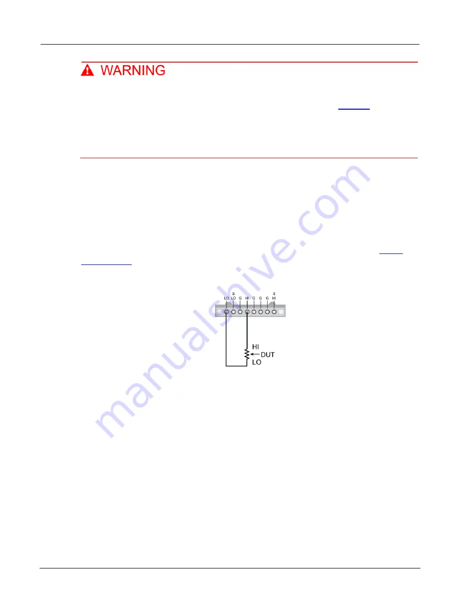
2-wire local sensing connections
You can use 2-wire local sensing measurements, shown in the following figure, for the following
source-measure conditions:
•
Sourcing and measuring current.
•
Sourcing and measuring voltage in high impedance (more than 1
kΩ) test circuits.
When using 2-wire local sensing connections, make sure to properly configure the 2600B
(on page 4-30).
Figure 28: Two-wire resistance connections
4-wire remote sensing connections
When sourcing and measuring voltage in a low-impedance test circuit, there can be errors associated
with lead resistance. Voltage source and measure accuracy are optimized by using 4-wire remote
sense connections. When sourcing voltage, 4-wire remote sensing ensures that the programmed
voltage is delivered to the DUT. When measuring voltage, only the voltage drop across the DUT
is measured.
By default, the 2600B instruments are configured to use 2-wire (local) voltage sensing. If you choose
to enable 4-wire (remote) voltage sensing, it is critical that you establish and maintain the proper
Kelvin connections between the corresponding force and sense leads to ensure the proper operation
of the instrument and to make accurate voltage measurements. Sense HI must be connected to
Force HI, and Sense LO must be connected to Force LO.


