background image

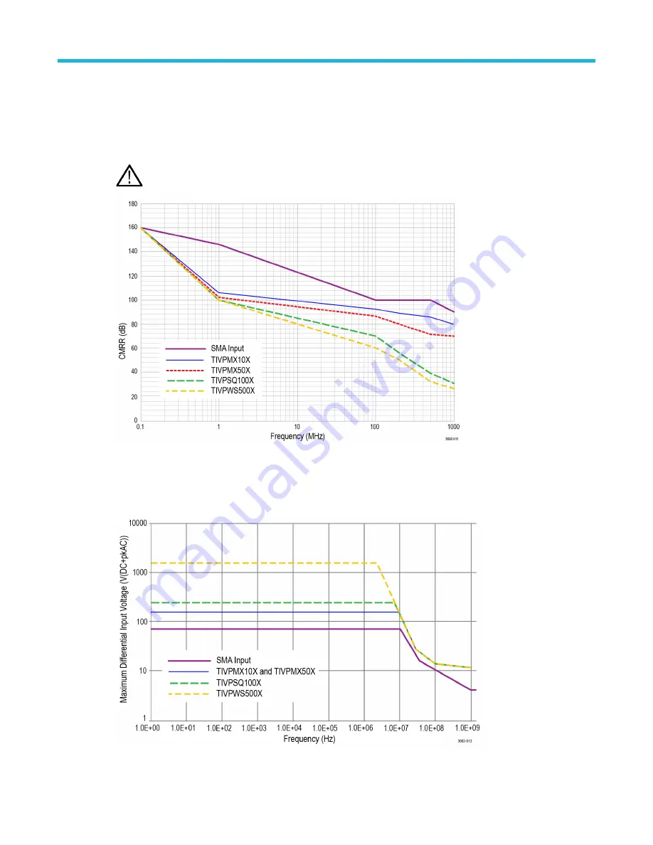
Common mode rejection ratio graphs

The ability to measure common mode rejection ratios (CMRR) of the IsoVu system below 100 kHz is limited by the dynamic
range of test systems. Due to the optical isolation of the IsoVu sensor head, the DC CMRR performance of all tip cables is
expected to be greater than 160 dB.

The following figure shows the typical CMRR values for the supported sensor tip cables. 

Note: The values for the TIVPMX50X, TIVPSQ100X, and TIVPWS500X sensor tip cables are preliminary.

Figure 7: Typical CMRR values for the sensor tip cables

Maximum differential input voltage vs frequency derating graphs

The following figure shows the derating values for the supported sensor tip cables.

Figure 8: Maximum differential input voltage vs. frequency for the sensor tip cables

Reference information

TIVP Series  IsoVuTM Measurement System User Manual 

37

Summary of Contents for IsoVu TIVP Series

Page 1: ...TIVP Series IsoVuTM Measurement System User Manual P 071369200 071 3692 00...

Page 2: ......

Page 3: ...VP Series IsoVuTM Measurement System User Manual Supports MSO 4 5 6 Series Firmware version 1 28 and above Register now Click the following link to protect your product www tek com register 071 3692 0...

Page 4: ...ued and pending Information in this publication supersedes that in all previously published material Specifications and price change privileges reserved TEKTRONIX and TEK are registered trademarks of...

Page 5: ...cation 20 Product description 21 Compensation box 21 Sensor head 21 Sensor tip cables 21 Models 22 Supported oscilloscopes 22 Accessories 22 Standard accessories 22 Optional accessories 23 Getting sta...

Page 6: ...e sensor tip cables 41 Probe tip tripod 41 Installing the probe tip adapters 41 Installing the square pins on the circuit board 43 User service 45 Service offerings 45 Warranty repair service 45 Calib...

Page 7: ...sor head 39 Figure 11 Sensor tip cable 39 Figure 12 Compensation box 39 Figure 13 Block diagram 40 Figure 14 Square pin series sensor tip cables 41 Figure 15 Connecting to an adapter on the circuit bo...

Page 8: ...quired equipment for performance verification 45 Table 6 Test record table 47 Table 7 STATUS LED descriptions 48 Table 8 SELF CAL LED descriptions 48 Table 9 INPUT LED descriptions 48 Table 10 ALT Mod...

Page 9: ...r products returned to any other locations This warranty shall not apply to any defect failure or damage caused by improper use or improper or inadequate maintenance and care Tektronix shall not be ob...

Page 10: ...IRE LAWFULLY OR THAT IS NOT A LEGITIMATE AUTHORIZED COPY OF TEKTRONIX S SOFTWARE THIS AGREEMENT EXPRESSLY EXCLUDES ANY RIGHTS CONCERNING SUCH ILLEGITIMATE COPIES IF THESE TERMS ARE NOT ACCEPTABLE THE...

Page 11: ...e Software or Equipment designed to control the manner in which they are used or harvest or mine Tektronix s proprietary content or information from the Software or Equipment THE SOFTWARE MAY NOT BE U...

Page 12: ...E USE OF THE SOFTWARE IN CONJUNCTION WITH OTHER PRODUCTS OR SERVICES INCLUDING THIRD PARTY PRODUCTS OR SERVICES OR 5 INDEMNIFICATION OF YOU OR OTHERS FOR COSTS DAMAGES OR EXPENSES RELATED TO THE GOODS...

Page 13: ...ith respect to its use and do not undertake to furnish any support or information relating thereto GENERAL Unless the Customer is the United States Government this Agreement contains the entire agreem...

Page 14: ...IN CONTRACT STRICT LIABILITY OR TORT INCLUDING NEGLIGENCE OR OTHERWISE ARISING IN ANY WAY OUT OF THE USE OF THIS SOFTWARE EVEN IF ADVISED OF THE POSSIBILITY OF SUCH DAMAGE http www freescale com mail...

Page 15: ...Open License WOL Permission to use copy modify distribute and sell this software and its documentation for any purpose is hereby granted without fee provided that the above copyright notice and this l...

Page 16: ...ers supplied with the product or indicated by Tektronix to be suitable for the product Observe all terminal ratings To avoid fire or shock hazard observe all rating and markings on the product Consult...

Page 17: ...nergize the test circuit before connecting or disconnecting the sensor tip cable Terms in this manual These terms may appear in this manual Warning Warning statements identify conditions or practices...

Page 18: ...ation and Requirements Edition 3 2014 US 21CFR PT1010 Performance Standard for Electronic Parts 2015 US 21CFR PT1040 Performance Standards for Light Emitting Products 2015 Equipment type Test and meas...

Page 19: ...on provides information about the environmental impact of the product Product end of life handling Observe the following guidelines when recycling an instrument or component Equipment recycling Produc...

Page 20: ...ejection ratio at DC 140 dB 10 million to 1 at 1 MHz 120 dB 1 million to 1 at 100 MHz and 80 dB 10 000 to 1 at 1 GHz Differential voltages up to 2500 Vpk sensor tip cable dependent Large common mode v...

Page 21: ...The buttons and indicators on the comp box provide a means for controlling the probe and indicating the overall status Sensor head The sensor head provides an interface between the device under test D...

Page 22: ...following table list the accessories that are shipped with the probe Accessory Description Part number The 10X MMCX Tip is included in every TIVP The MMCX tip is recommended for the best bandwidth and...

Page 23: ...nnector TIVPWS500X 1X MMCX sensor tip cable TIVPMX1X Square Pin to MMCX Adapter 0 062 Spacing 131 9677 xx Probe Tip Tripod Support 352 1170 xx Lead MMCX to IC Grabber 196 3546 xx Lead Square Pin to IC...

Page 24: ...optic cable smaller than 5 inches 12 7 cm Do not twist the fiber optic cable twisting the cable will stress the optical fibers Do not allow kinks or knots to develop in the fiber optic cable Avoid put...

Page 25: ...midity Operating Comp box 5 to 85 RH Relative Humidity at up to 40 C non condensing Probe head 5 to 85 RH Relative Humidity at up to 40 C 5 to 45 RH above 40 C up to 50 C non condensing Tip Cable Adap...

Page 26: ...as recommended in this document Do not access the RF Burn Hazard Zone while taking measurements on a live circuit While measuring high frequency common mode signals there is a risk of RF burns Refer t...

Page 27: ...termination For more information on the state of the LED see Table 9 INPUT LED descriptions on page 48 4 MENU button Press to open the Probe Vertical menu on the oscilloscope 5 ALT mode indicator Dis...

Page 28: ...void possible damage to the equipment do not connect the coaxial common shield of the sensor tip cable or SMA input to the high impedance portion of a circuit The additional capacitance can cause circ...

Page 29: ...erform the self calibration before connecting the tip cable to the DUT and taking the measurement 5 Connect the sensor tip cable end to the DUT If you are using MMCX sensor tip cable connect it to an...

Page 30: ...he self calibration 1 Connect probe to an oscilloscope channel 2 Press the SELF CAL button on the probe compensation box The Self Cal indicator LED will blink while self calibration is in process 3 Se...

Page 31: ...to start and monitor self calibration and a status query to determine if self calibration is needed AutoZero AutoZero and self calibration work on different parts of the measurement system Self calibr...

Page 32: ...are selectable when Range Mode is set to Manual The recommended V div settings are displayed in the table below The ranges shown are for the probe SMA input and 1X tip Multiply the range and V div se...

Page 33: ...tip cable Start at the top of the table and work down Choose the first tip that meets all of your criteria Table 3 Sensor tip cable selection Sensor tip cable Most sensitive V div setting Dynamic ran...

Page 34: ...l input range is limited and depends on the tip attenuation the gain range selected and the applied offset The input voltage conditions are divided into several different input ranges Common mode volt...

Page 35: ...ent Performance verification procedures on page 45 Overview Characteristic TIVP1 TIVP05 TIVP02 Bandwidth 1 GHz 500 MHz 200 MHz Rise time 450ps 850ps 2ns Differential Input Voltage Range Offset Range D...

Page 36: ...ain accuracy 2 System noise rms Sensor tip cable 20 mV range most sensitive 320 mV range 5 V range widest range SMA Input 50 mode 0 43 mV rms 1 46 mV rms 48 mV rms SMA Input 1 M mode 0 43 mV rms 1 46...

Page 37: ...ure shows the typical CMRR values for the supported sensor tip cables Note The values for the TIVPMX50X TIVPSQ100X and TIVPWS500X sensor tip cables are preliminary Figure 7 Typical CMRR values for the...

Page 38: ...VP physical specifications Table 4 Physical specifications Characteristic Description Net weight Weight does not include accessories and packaging Tip cable assembly 25g 0 055 lb Probe head 0 363 kg 0...

Page 39: ...Probe dimensions Figure 10 Sensor head Figure 11 Sensor tip cable Figure 12 Compensation box Reference information TIVP Series IsoVuTM Measurement System User Manual 39...

Page 40: ...F when the sensor head is placed six 6 inches 15 25 cm above a ground plane To minimize the effects of common mode capacitive loading consider the following items Whenever possible choose a reference...

Page 41: ...shows an example of connecting to an adapter on the circuit board with the tripod it reduces stresses on the test point Figure 15 Connecting to an adapter on the circuit board with the probe tip trip...

Page 42: ...h down on the adapter to seat it in place on the circuit board Figure 18 Pushing the MMCX to 0 062 inch 1 57 mm adapter in place Figure 19 Pushing the MMCX to 0 1 inch 2 54 mm adapter in place When th...

Page 43: ...to remove the spacer as shown in the figure Figure 21 Removing the header from square pins on the circuit board Tektronix provides a set of solder pins 0 018 inch 0 46 mm diameter to install on the c...

Page 44: ...solder pins into the soldering aide as shown in the following illustration Figure 22 Using the soldering aide to install the square pins on the circuit board 2 Use the soldering aide to hold the squa...

Page 45: ...ntenance CAUTION To prevent damage to the measurement system do not expose it to sprays liquids or solvents Avoid getting moisture inside the comp box or sensor head when cleaning the exterior Clean t...

Page 46: ...up action 2 Run Signal Path Compensation if recommended in Utility Calibration 3 Run the self calibration routine Self calibration on page 30 4 Enable the TIVP Channel and use the following Vertical m...

Page 47: ...n procedures Table 6 Test record table Model number Serial number Procedure performed by Date System RMS noise performance check Probe Range Limit Test result TIVP1 20 mV 1 mV RMS TIVP05 20 mV 0 7 mV...

Page 48: ...may be required Red Blinking Self Test failure No Power to probe head Try unplugging and plugging back in Service of probe may be required Table 8 SELF CAL LED descriptions LED Status Green Solid Sel...

Page 49: ...lower noise There is no signal detected the waveform is a flat line Remove the sensor tip cable and check its continuity referencing the input impedance table Try putting a signal directly into the pr...

Page 50: ...el is specified by x Syntax CH x PRObe Examples CH2 PROBE might return 1 0000E 01 RESISTANCE 1 0000E 07 UNITS V ID TYPE 10X SERNUMBER N A for a 10X probe indicating that among other parameters the att...

Page 51: ...attached to the Channel 1 input CH1 PROBE FORCEDRANGE 5 0 sets the attached probe to its 5 V range CH3 PROBE FORCEDRANGE might return 5 0000 indicating that the range of the probe attached to the Cha...

Page 52: ...ce of the probe that is attached to the specified channel The channel is specified by x Syntax CH x PRObe RESistance Examples CH2 PROBE RESISTANCE might return 10 00000E 6 indicating that the input re...

Page 53: ...us Returns Returns an integer number that represents the sum total of binary error bits B0 B15 The error bits are not displayed they are concatenated into the integer value The following is a list of...

Page 54: ...fies an external attenuation which is connected between the your input signal and the input of the probe attached to Channel 1 CH2 PROBEFUNC EXTATTEN might return 1 0000E 00 indicating that the probe...

Page 55: ...ent turns on external units NR1 0 turns off external units any other value turns on external units Examples CH2 PROBEFunc EXTUnits STATE ON turns on external units CH2 PROBEFunc EXTUnits STATE might r...

Page 56: ...ut offset 33 input specifications 25 installing the probe tip adapters 42 Iowegian ScopeIIR xv IsoVu 20 L laser certification 20 M measurement system setup 46 menu button 32 MMCX connectors 21 models...

Page 57: ...rs 29 square pin connectors 21 standard accessories 22 supported oscilloscopes 22 T test record 47 TIVP02 22 TIVP05 22 TIVP1 22 troubleshooting 48 U user service 45 V voltage vs frequency derating gra...

Reviews: