background image

Locating Signals

The SPI bus signals are set as follows:

SCLK is the rising edge latch

SS is active low

MOSI is active high

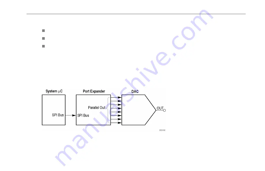
This is the beginning of the mixed signal chain. See the descriptions of these signals: DAC Input, Parallel, and DAC Output.

Packets occur approximately every 5 ms. The SPI packet contents are transferred to the Parallel DAC Input bus at the end of the
packet. The Parallel DAC Input bus then changes the voltage output of the DAC.

The resulting DAC output is a sine wave with an amplitude of 0 to 3 volts, and a period of 310 ms.

The clock rate is a 100 kHz, 0 to 5 volt signal.

Figure 2: Mixed signal chain block diagram

Demo 2 Board Instruction Manual

115

Summary of Contents for DPO2000 Series

Page 1: ...x MSO DPO2000 MSO DPO3000 and MSO DPO4000 Series Oscilloscope Demo 2 Board ZZZ Instruction Manual P071234701 071 2347 01 ...

Page 2: ......

Page 3: ...MSO DPO2000 MSO DPO3000 and MSO DPO4000 Series Oscilloscope Demo 2 Board ZZZ Instruction Manual xx www tektronix com 071 2347 01 ...

Page 4: ... all previously published material Specifications and price change privileges reserved TEKTRONIX and TEK are registered trademarks of Tektronix Inc FilterVu and Wave Inspector are trademarks of Tektronix Inc For safety information on your oscilloscope refer to its user manual Contacting Tektronix Tektronix Inc 14200 SW Karl Braun Drive P O Box 500 Beaverton OR 97077 USA For product information sal...

Page 5: ...VIII Saving a Screen Image 17 Giving Demos of Advanced Oscilloscope Features 21 Overall Package 21 MSO DPO4000 Series Performance 22 MSO DPO3000 Series Performance 23 MSO DPO2000 Series Performance 24 Wave Inspector Demos 25 Demo IX Setting Up I2C Signals 26 Demo X Using the Wave Inspector s Zoom and Pan Functionality 31 Demo XI Using the Wave Inspector s Search Functionality 37 Demo XII Using Ser...

Page 6: ...iscovering Per Channel Thresholds MSO4000 Only 89 Demo XIX Labeling Channels MSO2000 MSO3000 and MSO4000 Models 91 Demo XX Exploring Parallel Buses MSO2000 MSO3000 and MSO4000 Models 93 Demo XXI Triggering on Parallel Bus Data Values MSO2000 MSO3000 and MSO4000 Models 99 Demo XXII Searching for Parallel Bus Data Values MSO2000 MSO3000 and MSO4000 Models 102 Demo XXIII Zooming in on White Edges MSO...

Page 7: ...orresponding oscilloscope user manual NOTE The MSO4000 and DPO4000 series oscilloscopes described in this manual require firmware version 2 XX or higher To check the firmware version number push the Utility front panel button and view the Version If your oscilloscope uses firmware version 1 XX download new firmware and update your oscilloscope using procedures described in your oscilloscope user m...

Page 8: ...host side of the USB cable to the USB port on the lower left corner of the oscilloscope front panel or to either of the two USB host ports on the rear panel of some models 2 Connect the other end of the cable to the device port on the Demo 2 board 3 The POWER LED will light on the Demo 2 board 2 Demo 2 Board Instruction Manual ...

Page 9: ...he P2221 with the MSO DPO2000 or the P6139A with the MSO DPO3000 or MSO DPO4000 Then connect the ground lead of the probe to a point labeled GND on the Demo 2 board Attach the probe tip to the square pin on the Demo 2 board labeled CNT CLK NOTE CNT CLK is a clock used for a synchronous counter Demo 2 Board Instruction Manual 3 ...

Page 10: ...ck to a known starting point In general this is a good thing to do any time you are starting a new task 6 Push Autoset Autoset automatically adjusts the horizontal vertical and trigger parameters to give a usable display of the signal of interest You should now see several cycles of the clock signal 4 Demo 2 Board Instruction Manual ...

Page 11: ...Getting Started with the MSO DPO2000 MSO DPO3000 and MSO DPO4000 Series Oscilloscopes Demo 2 Board Instruction Manual 5 ...

Page 12: ... directions and observe how the display changes Also notice the channel 1 readout on the lower left of the display shows the current volts div setting Set the Vertical Scale to 1 V div 2 Turn the front panel channel 1 Vertical Position knob in both directions and observe how the display changes Position the waveform in the center of the display 6 Demo 2 Board Instruction Manual ...

Page 13: ... Started with the MSO DPO2000 MSO DPO3000 and MSO DPO4000 Series Oscilloscopes 3 Push the front panel channel 2 button to turn on channel 2 Push it again to turn off channel 2 Demo 2 Board Instruction Manual 7 ...

Page 14: ...Horizontal Scale to 200 ns div 2 Turn the front panel Horizontal Position knob both directions and observe the display Notice that this affects the trigger position icon the big T on an orange background Return the trigger position icon to center screen 3 Take a look at the graphic shown above the graticule The long yellow bar represents the overall acquisition while the gray brackets indicate the...

Page 15: ...the last acquired waveform on the display 2 Push Single to have the oscilloscope acquire a single waveform and then stop 3 Push the Run Stop button again to restart acquisitions Demo V Using Trigger Controls 1 Turn the Trigger Level knob in both directions and observe the display Turn it far enough to move the trigger level off the waveform Demo 2 Board Instruction Manual 9 ...

Page 16: ...ses its stable trigger and the waveform now appears to randomly scroll by 2 Push the Force Trig button once and notice that the oscilloscope shows a single acquisition for a moment This gives you an idea of what the waveform looks like so you can set an appropriate and stable trigger 10 Demo 2 Board Instruction Manual ...

Page 17: ...opes 3 On the MSO DPO4000 push the Set to 50 button This automatically sets the trigger level to the midpoint of the signal for a stable trigger On the MSO DPO2000 and MSO DPO3000 push the Level knob This will set the trigger level to the midpoint Demo 2 Board Instruction Manual 11 ...

Page 18: ...Cursors button Two vertical bar cursors now appear in the graphic above the graticule The corresponding cursor readout displays the time of each cursor relative to the trigger and amplitude along with the deltas between the cursors 2 Using the multipurpose a and b knobs bring the cursors on screen 12 Demo 2 Board Instruction Manual ...

Page 19: ...ace one cursor at the midpoint of the first falling edge Place the other cursor at the midpoint of the second falling edge to measure the signal s period The cursor readout should show a difference between the cursors of approximately 800 ns Hint To move the cursors more slowly turn the fine mode back on by pushing the Fine button if unlit on the front panel between the two multipurpose knobs Demo...

Page 20: ... Push Cursors two more times to turn them off Demo VII Taking Measurements 1 Push the front panel Measure button 2 Push the lower bezel Add Measurement button Add Mea surement Remove Measure ment Indicators More Bring Cursors on Screen Configure Cursors 14 Demo 2 Board Instruction Manual ...

Page 21: ...OK Add Measurement button Period 5 Push Menu Off to the lower right of the display to remove the side menu 6 Observe the measurement readout Frequency Period Value 1 250MHz 800 0ns Mean 1 250M 800 0n Min 1 250M 799 9n Max 1 250M 800 1n Std Dev 45 44 31 98 The readout indicates the frequency and period On the MSO DPO3000 and MSO DPO4000 it also shows the mean minimum maximum and standard deviation ...

Page 22: ...ush the lower bezel Remove Measurement button 8 Push the side bezel Remove All Measurements or Remove All button Remove All Measurem nts 9 Push Menu Off to the lower right of the display to remove the side menu Push it again to remove the lower bezel menu 16 Demo 2 Board Instruction Manual ...

Page 23: ...cilloscopes Demo VIII Saving a Screen Image 1 Insert a USB flash drive There is one USB 2 0 Host port on the front Some oscilloscopes also have one or more ports on the rear of the oscilloscope 2 Push the front panel Save Recall Menu button Demo 2 Board Instruction Manual 17 ...

Page 24: ...the MSO DPO2000 MSO DPO3000 and MSO DPO4000 Series Oscilloscopes 3 Push the lower bezel Save Screen Image button 4 If needed use multipurpose knob a to select the drive that you are using 18 Demo 2 Board Instruction Manual ...

Page 25: ... panel Select button This lets you expand or contract your view into the contents of the drive that you are using Expanded list Contracted list 6 Select the desired file format with the side bezel button File Format png 7 Push OK Save Screen Image OK Save Screen Image Demo 2 Board Instruction Manual 19 ...

Page 26: ... whenever you push the front panel Save button a screen image with an automatically incremented filename is saved to the storage location you specified To change what is saved each time you push the front panel Save button push the lower bezel Assign Save to button and then push one of the side bezel buttons Screen Image Waveform Setup or Image Waveform and Setup Assign Save to Image 20 Demo 2 Boa...

Page 27: ...anel USB ports make it easy to transfer screen images oscilloscope setups and waveform data from the oscilloscope to your workstation MSO DPO4000 models also have CompactFlash ports Some oscilloscopes also have one or more USB ports on the rear of the oscilloscope Short Depth MSO DPO2000 MSO DPO3000 and MSO DPO4000 series use a small amount of bench space especially given its performance level all...

Page 28: ...s Waveform Labels These oscilloscopes support adding labels to signals on the display This is increasingly useful as the number of signals on the display increases MSO DPO4000 Series Performance Characteristic DPO4104 MSO4104 DPO4054 MSO4054 DPO4034 MSO4034 DPO4032 MSO4032 Bandwidth 1 GHz 500 MHz 350 MHz 350 MHz DPO4000 Channels 4 4 4 2 MSO4000 Channels 4 16 4 16 4 16 2 16 Max Analog Sample Rate a...

Page 29: ... with very expensive options MSO DPO3000 Series Performance Characteristic DPO3054 DPO3052 MSO3054 DPO3034 DPO3032 MSO3034 MSO3032 DPO3014 DPO3012 MSO3014 MSO3012 Bandwidth 500 MHz 300 MHz 100 MHz DPO3000 Channels 4 or 2 4 or 2 4 or 2 MSO3000 Channels 4 or 2 16 4 or 2 16 4 or 2 16 Max Analog Sample Rate all channels 2 5 GS s 2 5 GS s 2 5 GS s Main Record Length all channels 5 M 5 M 5 M MSO3000 Mag...

Page 30: ...acteristic DPO2024 MSO2024 DPO2014 MSO2014 DPO2012 MSO2012 Bandwidth 200 MHz 100 MHz 100 MHz DPO2000 Channels 4 4 2 MSO2000 Channels 4 16 4 16 2 16 Max Analog Sample Rate all channels 1 GS s 1 GS s 1 GS s Main Record Length all channels 1 M 1 M 1 M 1 M Record Lengths on All Channels All MSO DPO2000 series oscilloscopes offer standard 1 M record lengths on all channels 24 Demo 2 Board Instruction M...

Page 31: ...ying to find what you are looking for on the Web these days without search engines like Google As record lengths have gotten longer virtually every digital oscilloscope has implemented a zoom model However most zoom models are operated with controls buried in menus or front panel controls that are multiplexed with other functions The zoom controls are easily accessible on the front panel The follo...

Page 32: ...he Demo 2 board Connect the probe from channel 1 on the oscilloscope to the I2C CLK test point on the Demo 2 board 2 Connect the ground lead of a second probe to a point labeled GND on the Demo 2 board Connect the second probe from channel 2 on the oscilloscope to the I2C DATA test point on the Demo 2 board 26 Demo 2 Board Instruction Manual ...

Page 33: ...e Features 3 Push the front panel Default Setup button 4 Turn the front panel Trigger Level knob to set the trigger level to approximately 2 V 5 Push the front panel channel 2 button to turn on channel 2 Demo 2 Board Instruction Manual 27 ...

Page 34: ...obs so that both channel 1 and channel 2 are set to 2 0 V div 7 Turn the channel 1 and channel 2 Vertical Position knobs to position channel 1 near the top of the graticule and channel 2 near the middle or bottom 8 Push the front panel Acquire button to display the acquire menu 28 Demo 2 Board Instruction Manual ...

Page 35: ...scale to 20 0 ms div on the MSO DPO4000 Set it to 2 0 ms div on the MSO DPO2000 and MSO DPO3000 Hint If you want to save this setup so that you can recall it at the beginning of each Demo 2 push the front panel Save Recall Menu button the lower bezel Save Setup button and select where you want to store the setup 11 Push the front panel Single button to acquire a single acquisition Demo 2 Board Ins...

Page 36: ...t the clock yellow ch1 and data blue ch2 lines of an I2C bus Hint If the waveforms do not look anything like the display to the right go back to step 1 and confirm that you connected both probes to the correct pins on the Demo 2 board 30 Demo 2 Board Instruction Manual ...

Page 37: ...an Functionality This section shows how to use the Wave Inspector s Zoom Pan knob to demonstrate zoom and pan functionality 1 Notice the Wave Inspector portion of the front panel This set of dedicated controls makes navigating and analyzing waveforms easier Demo 2 Board Instruction Manual 31 ...

Page 38: ...r pan knob 3 An inner zoom knob 4 Turn the zoom inner knob a few clicks clockwise The zoom feature should turn on You are seeing The entire acquisition in the top window What you are zooming in on within the gray top window brackets The zoomed view in the bottom window 32 Demo 2 Board Instruction Manual ...

Page 39: ...ld move the window quickly and then zoom back in when you arrived at the new location This is where the pan function helps 6 Turn the pan outer knob counterclockwise a bit Notice the extremely intuitive nature of the zoom pan controls Counterclockwise turning moves the zoom box left Clockwise turning moves the zoom box right The further you turn the pan knob the faster the zoom box moves You can m...

Page 40: ...he waveform should start scrolling Play speed is adjusted by turning the pan knob To pan in the other direction just turn the pan knob the other way to slow the zoom box down and have it change direction To quickly jump to another portion of the record and resume playing when done turn the pan knob all the way in that direction This is pan on top of play pause Push the play pause button again to s...

Page 41: ...e interested in mark it for further reference To do this push the Set Clear button on the front panel to place a mark Notice the solid white triangle that appears on the display Later you will see why the triangles are solid This triangle is like a bookmark on the waveform Demo 2 Board Instruction Manual 35 ...

Page 42: ...uter knob to quickly move to a few other interesting points in the waveform and place marks on them 10 Use the front panel previous and next arrow buttons arrows around Set Clear to navigate back and forth between marks instantly 36 Demo 2 Board Instruction Manual ...

Page 43: ...tures for manually navigating and inspecting the waveform NOTE To remove a mark with Set Clear first center the zoom box on the mark either with the and arrow buttons or panning on the mark Demo XI Using the Wave Inspector s Search Functionality This section shows how to use the powerful search engine to find events for you 1 Push the front panel Search button Demo 2 Board Instruction Manual 37 ...

Page 44: ...o select On Search On Off 4 Push the side bezel Clear All Marks button Clear All Marks You are removing the marks that you manually placed on the waveform 5 Push the lower bezel Search Type button and turn multipurpose knob a to select Pulse Width from a list of choices Search Type Pulse Width Review all the search choices available and the flexible capability of the your oscilloscope 38 Demo 2 Bo...

Page 45: ...tive below it If not push Polarity and then the side bezel Positive button 8 Push the bottom bezel Threshold button Then turn multipurpose knob a to set the threshold to approximately the midpoint of the channel 2 waveform e g 2 00 V 9 Push the lower bezel Set Mark When button If it is not already selected push the side bezel Pulse Width 8 00 ns button On the MSO DPO2000 use multipurpose knob b in...

Page 46: ... the Fine function Notice both the hollow white triangles placed in the graticule and the number of search events found shown in the lower left corner of the display Hollow triangles show search results and solid triangles show user placed marks Change the pulse width to 5 μs to show that as you adjust the search criteria the search results update Then change it back down to 2 μs 11 On the MSO DPO...

Page 47: ...lse that met the criteria For example try a zoom factor of 5kX on the MSO DPO4000 or 1kX on the MSO DPO2000 and MSO DPO3000 NOTE The oscilloscope displays the zoom value near the top of the display 14 When you finish this demo turn off Search by pushing the lower bezel Search button Search On If needed then push the side bezel Search button so it highlights Off Search On Off Demo 2 Board Instructi...

Page 48: ...gering and Analysis This demo shows a much easier and more efficient way to analyze your serial buses NOTE Start from where you finished the last demo 1 Turn the zoom inner knob to adjust your zoom factor to 250 X on the MSO DPO4000 or 200 X on the MSO DPO2000 and MSO DPO3000 Hint The oscilloscope will display the zoom value near the top of the display 42 Demo 2 Board Instruction Manual ...

Page 49: ...of Advanced Oscilloscope Features 2 Pan the zoom window as needed Notice how easy it is to set up a bus on the your oscilloscope while you do steps 3 through 9 3 Push the B1 button Demo 2 Board Instruction Manual 43 ...

Page 50: ...able NOTE The specific list of supported buses that you see depends on the model of oscilloscope used and the application modules installed The MSO DPO2000 s DPO2EMBD MSO DPO3000 s DPO3EMBD and MSO DPO4000 s DPO4EMBD modules support I2C 5 Push the lower bezel Define Inputs button Define Inputs 6 On the side menu confirm that the SCLK Input is set to channel 1 and that the SDA Input is set to chann...

Page 51: ... at about the midpoint of each waveform SCLK 1 Threshold a 2 40 V SDA 2 Threshold b 2 40 V 9 Push the front panel Menu Off button once to remove the side menu This extremely simple setup procedure steps 3 through 8 has just enabled you to define and decode a serial bus Demo 2 Board Instruction Manual 45 ...

Page 52: ...packet as indicated by a green vertical bar Address The yellow box shows the address R is read W is write Data The blue box shows the Data content Missing Ack as indicated by a red box with an exclamation point in it Stop end of packet as indicated by a red vertical bar 11 Push the lower bezel Bus Display button Display Bus Bus and Waveforms 46 Demo 2 Board Instruction Manual ...

Page 53: ...ures Hex 12 Select Binary from the side bezel menu to show that you can decode into either Hex or Binary Switch back to Hex as it is easier to view Binary Hex Binary 13 Push the lower bezel Event Table button Demo 2 Board Instruction Manual 47 ...

Page 54: ...to easily view the contents of every packet captured in the acquisition to trace system activity Includes timestamps for each packet This makes taking relative timing measurements easy Provides an easy way to view a lot of data on one screen Allows you to save the list in a CSV format 15 Push the side bezel menu Event Table button to select Off Event Table On Off 48 Demo 2 Board Instruction Manual...

Page 55: ...cilloscope Features 16 There is more to the Tektronix serial solution than just decoding and viewing bus waveforms There is also triggering and searching Push the front panel Trigger Menu button Demo 2 Board Instruction Manual 49 ...

Page 56: ...only have to define a bus once The rest of the oscilloscope like the trigger menu now knows what it is so you do not have to assign channels or thresholds again in this menu 19 Push the lower bezel Trigger On button Notice the list of trigger choices The key thing is that you can trigger on all the important components of an I2C packet Prior to this you had to hope that the acquisition you were ma...

Page 57: ...ush the lower bezel Address button 22 The side bezel Address button should already be selected Address XX 23 Turn multipurpose knobs a and b to enter a hex address of 50 While doing this notice the pre programmed addresses 24 Push the lower bezel Direction button Demo 2 Board Instruction Manual 51 ...

Page 58: ...Giving Demos of Advanced Oscilloscope Features I2C Direction Read Write 25 Select the side bezel Write button Read or Write 26 Push Single to make an acquisition 52 Demo 2 Board Instruction Manual ...

Page 59: ... 100 1 000 if needed so that you can read the bus address values found 28 Turn the pan outer knob to move the zoom box the gray bars at the at the top of the screen to the trigger position icon the T on an orange background to reveal what you have triggered on Demo 2 Board Instruction Manual 53 ...

Page 60: ...d Oscilloscope Features The waveform found illustrates that you have triggered on what you specified NOTE The trigger occurs after all the bits that constitute the search value have gone by 54 Demo 2 Board Instruction Manual ...

Page 61: ...the front panel Trigger Menu button if not already active Push the lower bezel Type button and turn multipurpose knob a to select Edge Setting the trigger back to Edge helps return random data for the search exercises described below 2 Push Single to make an acquisition 3 Push the front panel Search button Demo 2 Board Instruction Manual 55 ...

Page 62: ...lower bezel Search Type button and turn multipurpose knob a to select Bus from a list of choices 7 The source bus should already be set to B1 If it is not push the lower bezel Source Bus button and turn multipurpose knob a to select B1 On the MSO DPO3000 use the side menu 8 Push the lower bezel Search For button and turn multipurpose knob a to select from all of the criteria that you can search on...

Page 63: ...uttons to jump from one mark to the next This shows how easy it is to move from packet to packet 10 Push the lower bezel Search For button if it is not already active and select Address with multipurpose knob a 11 Push the lower bezel Address button Address XXX Demo 2 Board Instruction Manual 57 ...

Page 64: ...now Again jump around using the front panel previous and next arrow buttons 13 Push the lower bezel Search button and the side bezel Save All Marks button Save All Marks The hollow search marks became filled in They are now saved You could run a new search while keeping the old search results marked Very powerful 58 Demo 2 Board Instruction Manual ...

Page 65: ...ggering and Searching the MSO DPO2000 MSO DPO3000 and MSO DPO4000 series link the two so you can quickly copy your search settings into the trigger engine usually to acquire new data centered around the event of interest or copy your trigger settings into the search engine typically to see if any other trigger events occurred in the acquisition Demo XIV Monitoring and Decoding RS 232 Signals All M...

Page 66: ...Giving Demos of Advanced Oscilloscope Features 1 Attach a probe to channel 1 Then attach it to the Demo 2 board s GND point and RS 232_TX signal 60 Demo 2 Board Instruction Manual ...

Page 67: ...ault Setup 3 Push Autoset 4 Push Acquire 5 Push the lower bezel menu Record Length button if not already active and the side bezel menu 1M points button Mode Sample Record Length 1M Reset Horizontal Position Waveform Display Demo 2 Board Instruction Manual 61 ...

Page 68: ... 6 Turn the Horizontal Scale knob to select a time per division setting of 20 ms 7 Push B1 8 Push the lower bezel Bus button Bus RS 232 Define Inputs Thresholds Configure 9600 8 N B1 Label Bus Display Event Table 62 Demo 2 Board Instruction Manual ...

Page 69: ...he lower bezel Define Inputs button Look at the side menu and confirm that channel 1 is set to Tx Input If not set it there with multipurpose knob a NOTE With MSO oscilloscopes you can select both analog and digital channels to measure TX and RX signals 11 Confirm on the lower bezel Configure button that the bit rate is set to 9600 This is the default value 12 Push the lower bezel Bus Display butt...

Page 70: ... Features 13 Push Single 14 Turn the zoom inner knob of the Wave Inspector to zoom in on the decoded bus display until you can read the ASCII characters e g 10 X Notice that each box contains a character 64 Demo 2 Board Instruction Manual ...

Page 71: ...sh the Wave Inspector play button to have the oscilloscope scroll through the message so you can see what it says Push the play button again to stop the scrolling 16 Turn off zoom by pressing the front panel zoom button Demo 2 Board Instruction Manual 65 ...

Page 72: ...able button to select On Event Table On Off The event table presents information in an alternative way to the graphical bus waveform display It resembles a state listing window in a logic analyzer Notice that you can now view each character in the listing display 19 Turn off the event table 66 Demo 2 Board Instruction Manual ...

Page 73: ...ined in packets for easier reading of the ASCII data Demo XV Triggering on a Serial Data Pattern e g RS 232 MSO DPO2000 MSO DPO3000 and MSO DPO4000 series oscilloscopes can trigger on a user specified serial data pattern such as you would find in RS 232 data NOTE Install the appropriate DPO2COMP DPO3COMP or DPO4COMP application module before running this demo 1 Push Trigger Menu Demo 2 Board Instr...

Page 74: ...Mode Normal Holdoff 3 Push the lower bezel Trigger On button and use multipurpose knob a to select Tx Data 4 Push the lower bezel Data button Then push the side bezel Data button Enter the Hex value 54 ASCII character T with multipurpose knobs a and b Notice that the side bezel menu displays the character T for you 5 Push Menu Off 6 Push Single 68 Demo 2 Board Instruction Manual ...

Page 75: ...Giving Demos of Advanced Oscilloscope Features The oscilloscope should now trigger on the letter T Hex 54 You should see the word Tektronix on the display Demo 2 Board Instruction Manual 69 ...

Page 76: ...an filter and a background glitch capture min max sampled waveform FilterVu s foreground filtered waveform Reveals characteristics of your signal previously overshadowed by noise More precisely locates signal edges and amplitude levels increasing your confidence in cursor measurements Blocks out high frequency components of your signal that could cause your oscilloscope to alias FilterVu s backgro...

Page 77: ...ed Oscilloscope Features 1 Attach a P2221 probe to channel 1 on the MSO DPO2000 oscilloscope Then attach the probe to one of the GND points and to the Noisy Sine signal on the Demo 2 board Demo 2 Board Instruction Manual 71 ...

Page 78: ...Giving Demos of Advanced Oscilloscope Features 2 Push Default Setup 3 Turn the Horizontal Scale to 10 mS div 72 Demo 2 Board Instruction Manual ...

Page 79: ...vanced Oscilloscope Features 4 Turn the vertical Scale knob to 500 mV div 5 Adjust the vertical Position knob to center the waveform on the screen 6 Turn the Trigger Level knob to 1 3 V Demo 2 Board Instruction Manual 73 ...

Page 80: ...e waveform that you are looking at has high frequency noise on it use high frequency reject triggering to have the trigger ignore the noise and obtain a stable waveform It will provide a stable display without changing how the oscilloscope displays the waveform on the screen 7 Push the front panel Trigger Menu button 74 Demo 2 Board Instruction Manual ...

Page 81: ...ed Oscilloscope Features 8 Press the Coupling bottom bezel button Type Edge Source 1 Coupling HFReject Slope Level 1 3 V Mode Auto Holdoff 9 Press the HF Reject side bezel button HF Reject Demo 2 Board Instruction Manual 75 ...

Page 82: ...m the displayed sine waveform This waveform has noise on it included glitches that you may see come and go randomly In order to get a better view of the actual signal and filter out the noise turn on FilterVu and set the filter value to one that allows the desired waveform shape to come through 10 Press the front panel FilterVu button FilterVu 76 Demo 2 Board Instruction Manual ...

Page 83: ...Change the filter frequency by slowly turning Multipurpose a knob counter clockwise As you turn it towards the 2 2kHz limit at this horizontal scale setting you can see the change in the waveform The yellow foreground waveform now shows the true signal and has the noise filtered out With this setting the oscilloscope only passes through frequency content below 2 2 kHz It filters out the high frequ...

Page 84: ...he trace along with the noise signature on the waveform The background trace contains the peak detect information including transients 12 Turn Multipurpose b clockwise Change the intensity of the background waveform from 5 to 100 using this control 13 Turn the background trace off completely by pressing the Glitch Capture background side bezel button 78 Demo 2 Board Instruction Manual ...

Page 85: ...oax on the first channel of each pod is blue making it easy to identify The common ground uses an automotive style connector so that customers can easily create their own ground wires for connecting to their device under test When connecting to square pins the P6516 has an adapter that can be attached to the probe head extending the probe ground flush with the probe tip so that you can attach it t...

Page 86: ...s two buses simultaneously Setup Hold bus triggering The MSO models provide setup hold time violation triggering across an entire parallel bus including any or all of the 16 digital channels and the 4 analog ones You can trigger on all 20 analog and digital channels if you use Aux In as the clock Parallel bus triggering The MSO models add user defined logic triggering on a parallel bus You can ass...

Page 87: ...d DPO2000 models Tour the MSO Front Panel D15 D0 button Display or remove digital channels from the display and access the digital channel setup menu Bus buttons Define and display up to four different serial and parallel buses at a time with the MSO4000 and two buses with the MSO2000 MSO3000 Logic probe connector Plug the P6316 or P6516 digital probe with 16 digital connections into this front pa...

Page 88: ...iate Digital Probe from the oscilloscope front panel to the counter pins on the Demo 2 board For the MSO4000 connect each of the probe s digital group 1 channels D0 to D6 to each of the Demo 2 board s count signals CNT OUT 0 to CNT OUT 6 Connect the probe s D7 channel to the board s CNT CLK D7 CNT CLK D6 CNT OUT 6 D5 CNT OUT 5 D4 CNT OUT 4 D3 CNT OUT 3 D2 CNT OUT 2 D1 CNT OUT 1 D0 CNT OUT 0 82 Dem...

Page 89: ...be pin using the flush mount adapter For the MSO2000 MSO3000 and the P6316 simply plug the 16 connector pod into the corresponding 16 pin array on the Demo 2 board Be sure to line up the eight ground pins on the pod with the corresponding row of eight ground pins on the board Demo 2 Board Instruction Manual 83 ...

Page 90: ...l channel 1 button as many times as needed e g two times to remove the channel 1 waveform from the display 4 Turn the front panel Horizontal Scale knob to set the time division to 200 ns div 5 Push the front panel D15 D0 button Green Blue 84 Demo 2 Board Instruction Manual ...

Page 91: ...he display check that you properly connected the digital probe to both the oscilloscope and to the Demo 2 board in step 1 6 Confirm that the digital waveform height is already set to M medium on the lower bezel menu D15 D0 On Off Thresholds Edit Labels MagniVu On Off Height S M L 7 Push the lower bezel D15 D0 menu button not the front panel button with the same name On the resulting side menu D0 s...

Page 92: ...steps 9 through 11 9 Turn multipurpose knob a to highlight D1 10 Push the side bezel Display button to turn on the display of that channel 11 Push the Display button six more times to display channels D2 through D7 12 Push the front panel Trigger Menu button 13 Push the lower bezel Source button 14 Turn multipurpose knob a to select D7 as the trigger source 86 Demo 2 Board Instruction Manual ...

Page 93: ... 7 marker This is the channel s group marker When multiple channels are placed adjacent to each other on the screen they form a group Groups provide you with an easy way to set up multiple digital channels at once You can use the group to easily position multiple digital waveforms on the screen You can also use them to easily alter the voltage thresholds for all the channels in the group Demo 2 Bo...

Page 94: ...hlights the D7 base line indicator and then the right side D7 D0 channel row the display highlights the upside down triangle located above the D7 indicator and it simultaneously highlights all the channel indicators immediately below the triangle With the triangle and adjacent channel markers highlighted turn multipurpose knob b A white outline moves on the left side of the display when you turn t...

Page 95: ...t it to the group just move it adjacent to the other waveforms in the group Demo XVIII Discovering Per Channel Thresholds MSO4000 Only With the MSO4000 you can set a unique logic threshold for each digital channel This allows for defining different logic high and low voltage levels on different channels Other oscilloscopes including the MSO2000 MSO3000 only allow one threshold for eight or more si...

Page 96: ...on D15 D0 On Off Thresholds Edit Labels MagniVu On Off Height S M L Notice that you can set each channel s threshold voltage individually MSO4000 only or as a group with multipurpose knobs a and b For this exercise leave the thresholds the way they are On the MSO2000 MSO3000 you can set the threshold voltage for Group 1 or Group 2 90 Demo 2 Board Instruction Manual ...

Page 97: ...display increases it becomes more and more helpful to attach labels to each signal NOTE Start from where you finished the last demo In other words you should have pushed the front panel D15 D0 button to bring up the D15 D0 lower bezel menu 1 Connect a USB keyboard to one of the USB ports Use either the front panel or if available a rear panel USB port Demo 2 Board Instruction Manual 91 ...

Page 98: ...nt 1 Count 2 Count 3 Count 4 Count 5 and Count 6 Use the keyboard s Enter key or the side menu s down arrow key to select the next channel to label Alternatively you can add a label by pressing Select Preset Label then turning multipurpose knob b to select a preset label from a list and pressing the side menu Insert Preset Label button Try this out by adding the preset label CLOCK to D7 92 Demo 2 ...

Page 99: ... Buses MSO2000 MSO3000 and MSO4000 Models All MSO4000 MSO3000 and MSO2000 series oscilloscopes are designed to efficiently analyze parallel buses such as those used in embedded circuits The MSO s bus triggering and searching capabilities all support parallel bus analysis 1 Push the B1 button Demo 2 Board Instruction Manual 93 ...

Page 100: ... side bezel Number of Data Bits button and enter the number of bits as 7 by turning multipurpose knob a 5 Push the side bezel Define Bits to see a display of which bits are associated with which channels You can define the inputs with multipurpose knobs a and b The channels do not have to be in the same order as the bus You can select any of the 20 channels to represent the bus For this exercise l...

Page 101: ...move the side menu 7 Turn knob a to move the parallel bus display above the display of digital channels so you can more easily read the decoded bus Observe the decoded bus values on the display The bus transitions everywhere that the data transitions Demo 2 Board Instruction Manual 95 ...

Page 102: ...Demos of MSO Features Now let s create a clocked bus 8 Push Define Inputs from the lower bezel menu Bus B1 Parallel Define Inputs Thresholds B1 Label Bus Display Event Table 96 Demo 2 Board Instruction Manual ...

Page 103: ...firm that the side menu Number of Data Bits button is still set to 7 Number of Data Bits 7 12 Push the side menu Define Bits button if not already active Confirm that the source type is set to Clock If not turn a to select it Turn multipurpose knob b to select D7 as the clock source Define Bits a Clock b D7 13 Push Menu Off to the lower right of the display to remove the side menu Demo 2 Board Ins...

Page 104: ...me it sees a rising clock edge 15 Push the lower bezel Event Table button Push the side bezel Event Table button select On Notice that each data value in the table is displayed with its associated time stamp MSO oscilloscopes can export these values to a CSV file 16 Push Event Table to Off 17 Push Menu Off 98 Demo 2 Board Instruction Manual ...

Page 105: ...000 Models The MSO4000 MSO3000 and MSO2000 can trigger on specific parallel bus data values 1 Push the front panel Trigger Menu button 2 Push the lower bezel Type button Type Bus Source Bus B1 Parallel Data XX Mode Auto Holdoff 3 Turn multipurpose knob a to select Bus Demo 2 Board Instruction Manual 99 ...

Page 106: ...n 5 Turn multipurpose knobs a and b to enter a value of 7F in Hex all 1 s in Binary You are measuring a counter The oscilloscope will trigger when the counter reaches a state where all channels reach the 1 state green 6 Push Menu Off 100 Demo 2 Board Instruction Manual ...

Page 107: ...el Run Stop button Notice that the oscilloscope triggers when the 7F the all 1 s green data value you selected above occurs Triggering on a data pattern is a common request from engineers working on embedded designs Demo 2 Board Instruction Manual 101 ...

Page 108: ...ton 2 Push the lower bezel Search button and the side bezel Search button to turn search to On Search On Search Type Bus Source Bus Parallel Data 7X 3 Select the side bezel Copy Trigger Settings to Search The trigger settings used in the previous demo are now your search criteria Note that any white diamonds on the top of the display depict each incidence of the search value found in the record 10...

Page 109: ...el Data button Use the multipurpose a and b knobs to change the data value to 7X The X value stands for any value and will ensure the search returns as many or more results than did the previous step 5 Push Menu Off Demo 2 Board Instruction Manual 103 ...

Page 110: ... White vertical edges on displayed digital waveforms inform the user that more information is available at that point in the display You can zoom in on these white edges to see more details NOTE Run this demo with an MSO4104 MSO4054 or MSO4034 104 Demo 2 Board Instruction Manual ...

Page 111: ... Then attach the probe to one of the GND points and to the XTALK 1 signal on the Demo 2 board 2 Also attach a P6516 digital probe D0 to the XTALK 1 signal You have now attached both the analog and the digital probes to the same test point 3 Push Default Setup Demo 2 Board Instruction Manual 105 ...

Page 112: ...quire 5 Push the lower bezel menu Record Length button if not already active and the side bezel menu 1M points button Mode Sample Record Length 1M Reset Horizontal Position Waveform Display 6 Push D15 D0 106 Demo 2 Board Instruction Manual ...

Page 113: ... On Off Height S M L 8 Push Autoset 9 Turn the Horizontal Scale knob to select 1 μs as the time per division 10 Turn the channel 1 Vertical Position knob to position the analog channel 1 waveform near the middle of the top half of the graticule if it is not already there Demo 2 Board Instruction Manual 107 ...

Page 114: ...ttom half of the graticule 13 Push Thresholds Confirm that D0 is selected If not turn multipurpose knob a to select it Turn multipurpose knob b to set the threshold to 1 00 V 14 Push Menu Off 15 Push Run Stop Notice any vertical white edges on the digital waveform If none are visible push Run Stop again 108 Demo 2 Board Instruction Manual ...

Page 115: ...ow to bring one of the white edges to center screen Alternatively push the play button to do this 17 Turn the zoom inner knob of the Wave Inspector to zoom in on one of the white edges Note you can now see a narrow pulse that you couldn t see before you zoomed in Demo 2 Board Instruction Manual 109 ...

Page 116: ...Giving Demos of MSO Features This completes the Tektronix MSO DPO2000 MSO DPO3000 and MSO DPO4000 series demos 110 Demo 2 Board Instruction Manual ...

Page 117: ...r Demo 2 board does not appear to work Check the power If the Demo 2 board is receiving power the power indicator will be lighted If it is not try gently pushing in the power cable on the USB Device port Demo 2 Board Instruction Manual 111 ...

Page 118: ... you locate signal pins on connectors and on headers To find the desired signal on the diagram look up the grid location in the signal description and then use the grid to find that location on the diagram and on the board See Figure 1 112 Demo 2 Board Instruction Manual ...

Page 119: ...Locating Signals Figure 1 Tektronix Demo 2 board and locator grid Demo 2 Board Instruction Manual 113 ...

Page 120: ...ler DSP system I2C Bus Board label I2C_CLK I2C_DATA Connector grid location A2 G1 Description These are the I2C Inter IC Communication bus signals between the μC and a serial EEPROM There are several different types of data packets The clock rate is a 100 kHz 0 to 5 volt signal SPI Bus Board label SPI_SCLK SPI_SS SPI_MOSI Connector grid location F1 G1 G2 H1 Description These are the SPI Serial Per...

Page 121: ...AC Output Packets occur approximately every 5 ms The SPI packet contents are transferred to the Parallel DAC Input bus at the end of the packet The Parallel DAC Input bus then changes the voltage output of the DAC The resulting DAC output is a sine wave with an amplitude of 0 to 3 volts and a period of 310 ms The clock rate is a 100 kHz 0 to 5 volt signal Figure 2 Mixed signal chain block diagram ...

Page 122: ...iption for packet details DAC Output Board label DAC_OUT Connector grid location I2 Description This is the output of the DAC at the end of the mixed signal chain The DAC is driven from the port expander The DAC output is a sine wave Since the output is not filtered the digitizing levels are obvious in the output waveform See Figure 2 The resulting DAC voltage is a sine wave with an amplitude 0 to...

Page 123: ...twork bus signals between two CAN transceivers The bit rate of the data packet is 500 kbps LIN Bus Board label LIN Connector grid location B1 B4 Description This is the LIN Local Interconnect Network bus signal between two LIN transceivers The bus speed is 19 2 kbaud The signal contains a mix of version 1 x and 2 x frames RS232 UART Transmit Board label RS232_UART RS232_TX Demo 2 Board Instruction...

Page 124: ...e data format is 1 start bit and 8 data bits with no parity 2 ns Pulse Board label 2NS_PULSE Connector grid location B4 Description This signal is a 2 ns to 3 ns 2 5 V pulse at a 3 3 ms repetition rate Use this signal to demonstrate the minimum pulse width capture specification of an instrument s digital acquisition system 2 ns Pulse Trigger Board label 2NS_TRIG Connector grid location B4 Descript...

Page 125: ... Use them to demonstrate MagniVu Fast Edge Board label FAST_EDGE Connector grid location I3 Description This is a 156 kHz capacitively coupled square wave signal with a 3 ns rise and fall time Fast FF Clock Board label FAST_FF_CLK Connector grid location H5 Description This is the 1 25 MHz clock input signal to a fast flip flop Demo 2 Board Instruction Manual 119 ...

Page 126: ... to the clock input Fast FF Q Output Board label FAST_FF_Q Connector grid location H6 Description This is the Q output signal of the fast flip flop This signal shows metastable behavior infrequently Slow FF Clock Board label SLOW_FF_CLK Connector grid location H5 Description This is the 1 25 MHz clock input signal to a slow flip flop 120 Demo 2 Board Instruction Manual ...

Page 127: ...e clock input Slow FF Q Output Board label SLOW_FF_Q Connector grid location H5 Description This is the Q output signal of the slow flip flop This signal shows metastable behavior frequently Counter Clock Board label CNT_CLK Connector grid location B6 Description This is the 1 25 MHz clock signal for the 7 bit Counter Output described next Demo 2 Board Instruction Manual 121 ...

Page 128: ...als to demonstrate setup time and hold time bus triggering using MagniVu The Counter Output Bits and the Counter Clock signals are on eight adjacent sets of header pins for easy connection to a digital probe 350 ps Delayed Clock Board label 350_PS_DELAY_CLK Connector grid location H6 Description This is a 156 kHz square wave signal and a delayed copy Use the nominal 350 ps delay to demonstrate the...

Page 129: ...ly every 104 8 ms Use a Runt trigger to isolate the signal A 50 ns narrow pulse appears approximately every 104 8 ms Use a Pulse Width trigger to isolate the signal The pulse train is a repeating group of three pulses The three pulses are 100 ns 200 ns and 100 ns wide with a 100 ns low between The group repeats at a 1 6 μs rate The anomaly is a group of four pulses The four pulses are 100 ns 50 ns...

Page 130: ...three pulses The three pulses are 100 ns 200 ns and 100 ns wide with a 100 ns low between each pulse The group repeats at a 1 6 μs rate The anomaly is a group of four pulses The four pulses are 100 ns 50 ns narrow 100 ns runt and 100 ns wide with a 100 ns low between each pulse except for a 50 ns low before the runt 40 MHz Board label 40_MHZ Connector grid location A4 Description This is a 40 MHz ...

Page 131: ...escription This is a 200 ns wide positive pulse that is initiated by the SINGLE SHOT push button grid location I4 The Demo 2 board provides one pulse per button push 512 MHz Board label 512_MHZ Connector grid location C6 Description This is a 512 MHz 600 mV peak to peak sine wave signal that is enabled by the SINGLE SHOT push button grid location I4 FlexRay Board label FLEXRAY_BP FLEXRAY_BM FLEXRA...

Page 132: ...iver The data rate is at 10 Mb s The swing is 0 to 3 3 V Tri state is at 1 65 V BP and BM only There are 15 individual 198 bit long frames Reset Button Board label RESET Grid location E7 Description Press the RESET button to start RS 232 signals from a common start point Single Shot Button Board label SINGLE_SHOT Grid location I4 Description Push the SINGLE SHOT button to initiate a 200 ns pulse a...

Reviews: