background image

14 

AFG1022 Quick Start User Manual 

Instrument front panel, interface, and rear panel 


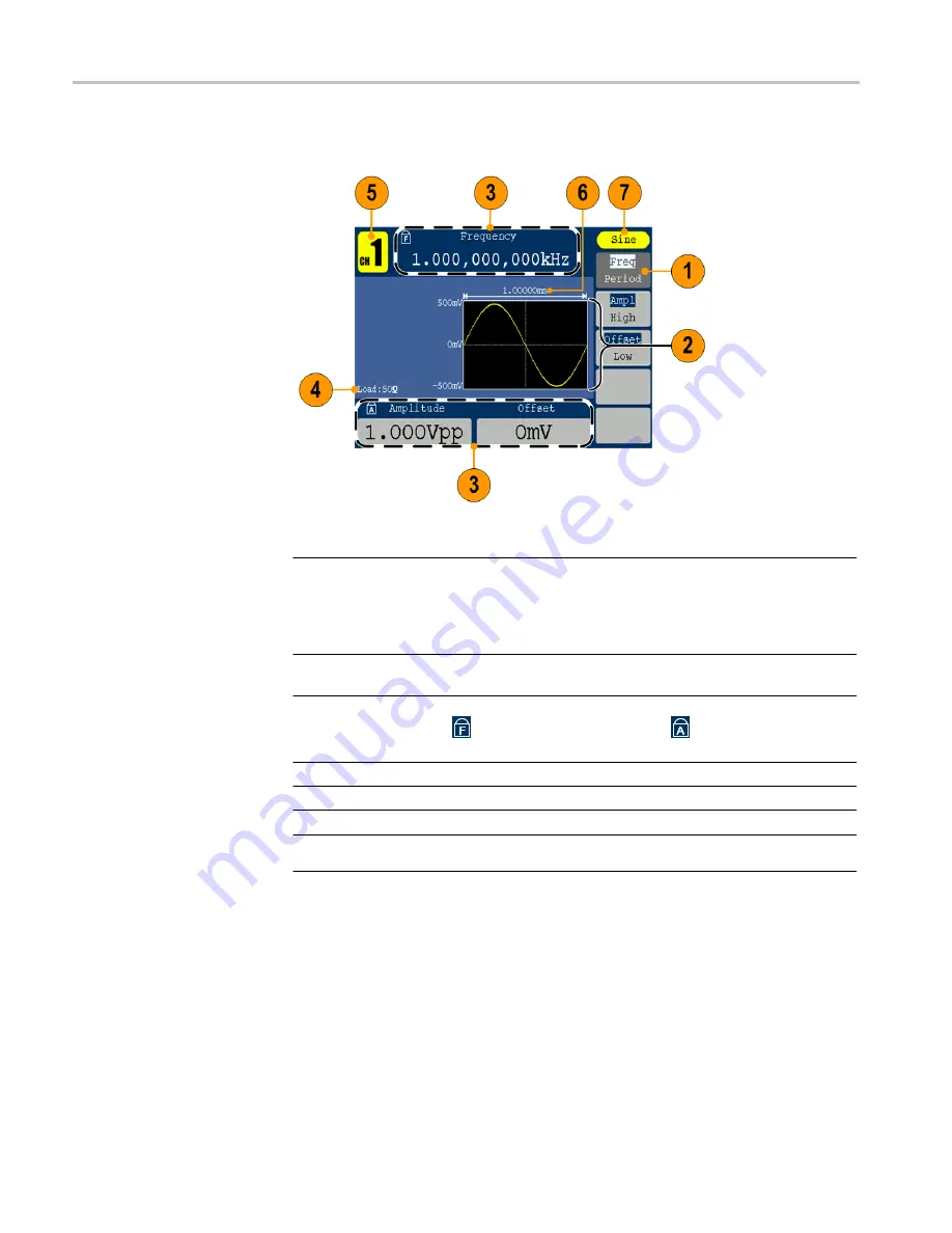
Parts of the screen interface 


Item 

Description


1


Bezel menu

: When you push a front panel button, the instrument displays 

the corresponding menu on the right side of the screen.  The menu shows 

the options that are available when you press the unlabeled bezel buttons 

directly to the right of the screen.  (Some documentation may also refer to 

the bezel buttons as option buttons, side-menu buttons, or soft keypad.) 

2


Graph  /  waveform  display  area

: This  part  of  the  main  display  area 

shows the signal as a graph or waveform. 

3


Parameter display area

:  This part of the main display area shows active 

parameters. 

  indicates Frequency Lock is on;    indicates Amplitude 

Lock is on.   

4


Message display area

: This part displays the load value 

5


Message display area

: This part displays the current channel. 

6


Parameter display area

: This part displays the period. 

7


Message display area

: This part displays the type of the current signal 

or the current mode. 

Summary of Contents for AFG1022

Page 1: ...AFG1022 Arbitrary FunctionGenerator Quick Start User Manual P077109700 077 1097 00...

Page 2: ......

Page 3: ...AFG1022 Arbitrary FunctionGenerator Quick Start User Manual www tektronix com 077 1097 00...

Page 4: ...and pending Information in this publication supersedes that in all previously published material Specifications and price change privileges reserved TEKTRONIX and TEK are registered trademarks of Tek...

Page 5: ...sible for paying all shipping charges duties taxes and any other charges for products returned to any other locations This warranty shall not apply to any defect failure or damage caused by improper u...

Page 6: ......

Page 7: ...nt output circuits 12 Instrument front panel interface and rear panel 13 Front panel overview 13 Parts of the screen interface 14 Default setup 15 Select waveform 17 Select run mode 19 Adjust waveform...

Page 8: ...tents ii AFG1022 Quick Start User Manual Sweep a waveform 33 Modulate a waveform 36 Generate a burst waveform 41 Copy channel setting 44 USB memory 45 Utility menu 46 Appendix A Line Fuse Replacement...

Page 9: ...m Purpose Location Important safety and compliance instructions Compliance and safety instructions Built in Help UI Help and Operation Quick Start User Manual Unpacking Installation Tutorials Operatio...

Page 10: ...e designed to meet your specific service needs Tektronix warrants this product as describe in the warranty statement at the front of this manual Tektronix technicians provide warranty service at most...

Page 11: ...instrument Feature Description Channel 2 Sine 25 MHz Pulse 12 5 MHz Arbitrary waveform 2 to 8 192 points 14 bit Sampling Rate 125 MS s Amplitude High Z 2 mVp p 20 Vp p 50 1 mVp p 10 Vp p Display Colo...

Page 12: ...nd Compliance Instructions 071 3419 xx AFG1022 Documentation CD containing the following PDF documents 063 4558 xx AFG1022 Arbitrary Function Generators Quick Start User Manual English 077 1097 xx Sim...

Page 13: ...or bench observing the following clearance requirements Sides 50 mm 2 in Rear 50 mm 2 in Temperature Before operating the instrument ensure the ambient temperature is between 0 C to 40 C 32 F to 104...

Page 14: ...on 2 Peel off the label on the power receptacle and if needed replace the fuse according to the line setting refer to Appendix A for the steps of fuse replacement before inserting the AC power cord In...

Page 15: ...e power on settings to the last powered off settings from the Utility menu using the following procedure 1 Push the front panel Utilitybutton 2 Press System 3 Press Power On to select from the followi...

Page 16: ...t time English is selected by default After you select a desired language all the bezel menus pop up messages and built in help are displayed in the specified language 1 Push the front panel Utility b...

Page 17: ...cate the channel output on the front panel Out1 means CH1 output and Out2 means CH2 output 2 Locate the Ref Clk Out on the rear panel 3 Locate the Ref Clk Counter In Ext Trig Burst Fsk In and Ext Mod...

Page 18: ...n the wipe with distilled water or a 75 isopropyl alcohol solution and gently rub the digital surface Avoid excess force or you might damage the display surface Clean the exterior surfaces with a dry...

Page 19: ...f the instrument during the update process NOTE The screen images of the following procedure are provided as an example The actual screen display might be different depending on your instrument config...

Page 20: ...vice is not inserted the Update firmware is disabled 7 Use the general purpose knob to select USBDEVICE and then press Enter to enter USBDEVICE to browse files in the USB memory 8 Select the downloade...

Page 21: ...NOTE If you accidentally removed the USB memory during the update process do not power off the instrument Repeat the installation process from step 3 10 Wait until the instrument displays a message sa...

Page 22: ...ow the equivalent output circuits Legend for the following images Output signals do not exceed 10 V whenthe 50 load impedance is used A change to the load impedance L will affect the output window max...

Page 23: ...meric point plus minus sign 3 General purpose knob 4 Channel copy button 5 Utility button 6 Help button 7 Arrow buttons allow you to select a specific number on the display screen when you are changin...

Page 24: ...y also refer to the bezel buttons as option buttons side menu buttons or soft keypad 2 Graph waveform display area This part of the main display area shows the signal as a graph or waveform 3 Paramete...

Page 25: ...efault values use the front panel Utility button as follows 1 Push thefront panel Utility button 2 Press System 3 Press Set to Default 4 Select one of the following Select to recall the default settin...

Page 26: ...1 Sweep start frequency 100 000 Hz Sweep stop frequency 1 000 kHz Sweep time 1 s Sweep type Linear Sweep source Internal Modulation only available in ch1 Modulation waveform 100 000 Hz Sine except FSK...

Page 27: ...waveforms You can create edit and save your custom waveforms You can also create modulated waveforms using the Mod panel button and then Mod bezel button menus The following table shows the combinatio...

Page 28: ...AFG1022 Quick Start User Manual Instrument front panel interface and rear panel Other available waveforms The following are examples of some other waveform types available in the Built in Waveform me...

Page 29: ...the four Run Mode bezel buttons to select the instrument signal output method Modulation sweeping and burst modes are only available in Ch1 1 The default Run Mode is Continuous 2 To select a modulated...

Page 30: ...to move the cursor 2 Or push the numeric panel button and an input box will pop up Input frequency value and choose proper unit Use BK SP panel button to delete character if input error occurs 3 Press...

Page 31: ...can configure the signal with the outputs off This will allow you to minimize the chance of sending a problematic signal to a DUT Display Both Channels 1 Push the front panel Both button to display th...

Page 32: ...use Voltage Fuse 100 120 V 250 V F1AL 220 240 V 250 V F0 5AL 3 Power line selector Switch between 110 V 220 V 4 USB type B connector This can be used to connect a USB type B controller 5 Ext Mod In Co...

Page 33: ...rument 2 Connect the Channel Output of the instrument to an oscilloscope input with a BNC cable 3 Select a waveform 4 Enable the signal output 5 Observe the waveform displayed on the oscilloscope scre...

Page 34: ...ion generator to an oscilloscope input connector 3 Push the front panel Sine button 4 The default run mode is Continuous after power on If it is not at Continuous mode push the front panel Mod button...

Page 35: ...Press Select to display the topic corresponding to the highlighted link 4 Press Previous to display a previous topic 5 Press Next to display the next topic 6 Press Back or push any front panel button...

Page 36: ...se waveform 1 Push the front panel Pulse button to display the Pulse screen NOTE All of the following parameters can be adjusted using the numeric keypad or the general purpose knob 2 Press Width Duty...

Page 37: ...he internal memory Use the front panel general purpose knob to scroll the files then select a file and press Select Or press Cancel to cancel the operation There are 45 kinds of Built in waveforms see...

Page 38: ...rithm function X 3 Cubic function CauchyDistr Cauchy distribution BesselJ BesselI function BesselY BesselII function ErrorFunc Error function Airy Airy function Windows Rectangle Rectangle window Gaus...

Page 39: ...ers directly or use the numeric keypad to adjust and then choose the proper unit X1 X1000 The waveform points range is 2 to 8192 5 Press Intrpl to switch Interpolation On Off On means the points will...

Page 40: ...first insert a USB memory device into the port on the front panel Use the general purpose knob to select USBDEVICE and then press Enter The instrument lists a directory of the folders and files on the...

Page 41: ...ugh User 255 Press CallOut If a prompt File read successful appears go back to the waveform interface and view the waveform NOTE The file size is displayed on the right side 0B indicates the file is e...

Page 42: ...he general purpose knob or the numeric keypad to adjust Ampl High Offset and Low NOTE You cannot modulate sweep or burst noise waveform Generate DC 1 Push the front panel Arb button 2 Press Built in 3...

Page 43: ...1022 Quick Start User Manual 33 Sweep a waveform The Sweep outputs a waveform with the output signal frequency varying linearly or logarithmically Start frequency Stop frequency Sweep time Center freq...

Page 44: ...rFreq Use the general purpose knob or the numeric keypad to set the start or the center frequency 6 Press StopFreq FreqSpan Use the general purpose knob or the numeric keypad to set the stop frequency...

Page 45: ...n a stop frequency the instrument sweeps from the low frequency to the high frequency If a start frequency is higher than a stop frequency the instrument sweeps from the high frequency to the low freq...

Page 46: ...Select AM as the modulation type 4 Press Source to select Internal or External If the source is External use the Ext Mod In connector in the rear panel to input the external signal the setting of AM...

Page 47: ...to input the external signal the setting of FM is finished If you choose Internal continue with the steps below 5 Press Shape to select among sine square ramp or arb as the modulating waveform 6 Pres...

Page 48: ...Select PM as the modulation type 4 Press Source to select Internal or External If the source is External use the Ext Mod In connector in the rear panel to input the external signal the setting of PM i...

Page 49: ...by the Ext Trig FSK Burst connector in the rear panel The user interface of the FSK is shown as below 1 Select a waveform and then push the front panel Mod button 2 Press Mod In this example use the...

Page 50: ...m The following equations show the output amplitude of AM FM and PM modulation in this example sine waveform is used for carrier waveform and modulation waveform AM Output Vp p FM Output Vp p PM Outpu...

Page 51: ...red burst mode A specified number burst count of waveform cycles are output when the instrument receives a trigger input from the internal trigger source an external trigger source a remote command or...

Page 52: ...ect noise waveform as a carrier waveform 3 Press N Cycle Gated to select N Cycle 4 Press Trigger Interval to set the trigger interval 5 Press Start Phase to set start phase The start phase defines the...

Page 53: ...t mode push the general purpose knob on the front panel to output a burst signal To generate a gated burst waveform 1 Select a waveform and then push the front panel Mod button 2 Press Burst NOTE You...

Page 54: ...ay the submenu 2 Press CH2 To CH1 to copy parameters of CH2 to CH1 3 Press CH1 To CH2 to copy parameters of CH1 to CH2 4 Press FreqLock to toggle between On and Off At on status the frequency of the t...

Page 55: ...you plug in a USB memory device to the instrument a caution message appears on the screen Do not remove the USB memory device until the message disappears If you remove the USB memory device while thi...

Page 56: ...15 5 System setup related menus see step 16 6 Press Display Setup to display the submenu 7 Press BckLight use the general purpose knob to adjust the value on the current cursor and use to move cursor...

Page 57: ...is a better choice 13 Press HFR to select ON or OFF High frequency restrain is used for filtering the high frequency signal in measuring the low frequency signal and improve the measure accuracy To me...

Page 58: ...e proper unit The load range is 1 to 10 K NOTE Please setup the correct load for right application 16 Press System to display the submenu Language See page 6 Select a local language PowerOn See page5...

Page 59: ...se the operator to hazardous voltages that could result in personal injury or death Use only the correct fuse type Failure to do so could result in personal injury or instrument damage Voltage Fuse 10...

Page 60: ...burst waveform generate 43 Generate a burst waveform 42 Generate a pulse waveform 26 Generate a sine waveform 24 Generate an arbitrary waveform 27 Generate DC 32 Generate Noise 32 Graph display area...

Page 61: ...waveform 33 T To adjust waveform parameters 20 To generate a pulse waveform 26 To generate a sine waveform 24 To generate an built in waveform 27 To create save a user defined waveform 29 To protect...

Reviews: