


Configure the instrument
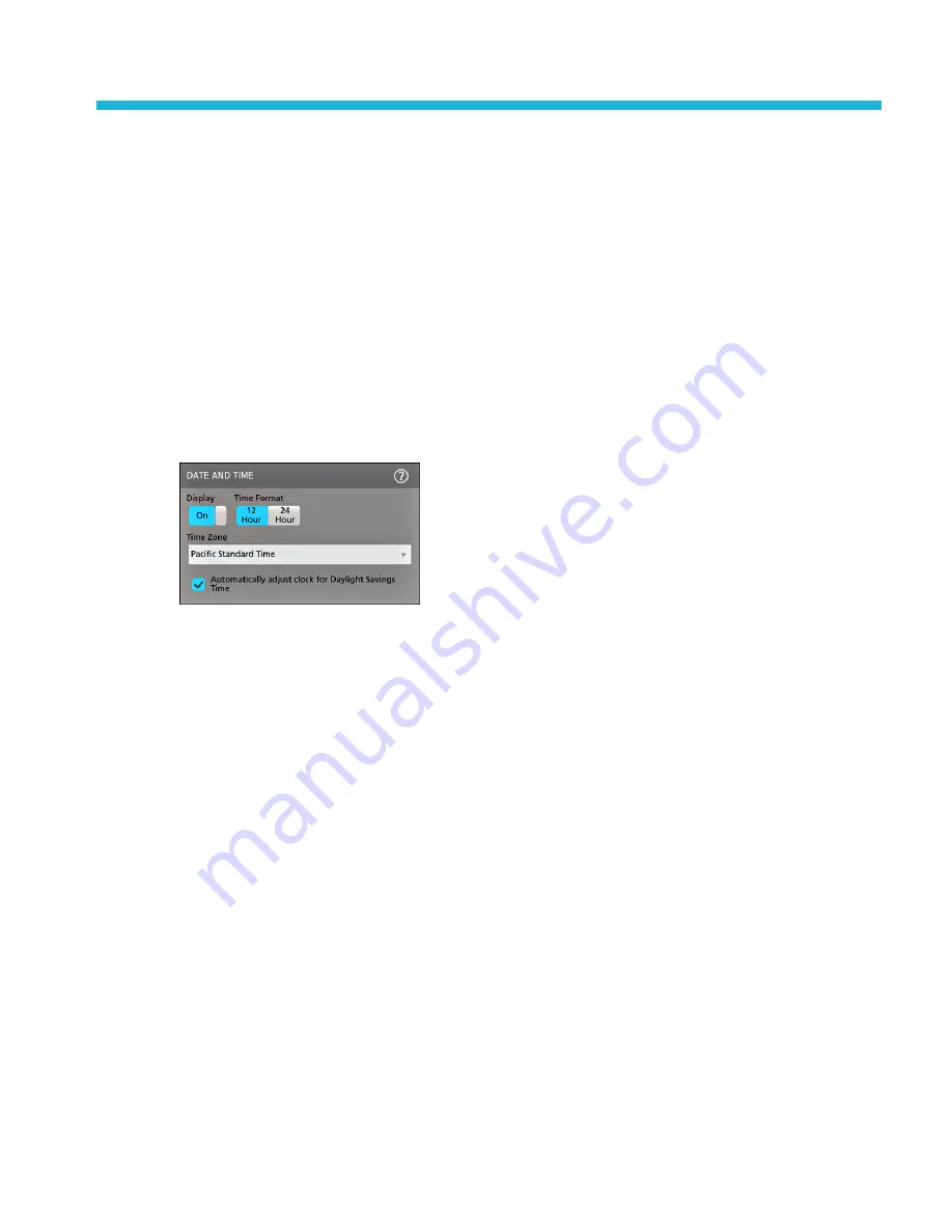
Set the time zone and clock readout format
Set the time zone to your region so that saved files are marked with the correct date and time information. You can also set the
time format (12 or 24 hour clock).
To access the user interface on the MSO58LP, connect a monitor to a video port on the rear of the instrument, and connect a
mouse to any USB Host port. You do not need to connect a mouse if your remote monitor is touch-capable. You can also
remotely access the user interface of a network-connected instrument by entering the instrument's IP address in a web browser.
To remotely set this control or run this task on an MSO58LP, see the oscilloscope Programmer Manual (Tektronix part number
077-1305-xx) for the correct command or commands to use.
1. Double-tap the Date/Time badge (bottom-right of screen) to open the configuration menu.
2. To turn off showing the date and time on the screen, tap the Display button to Off.
To turn on date/time display again, double-tap in the blank area where the date/time badge was displayed to open the
configuration menu, and set the Display button to On.
3. Select a time format (12 Hour or 24 Hour).
4. Tap the Time Zone field and select the time zone that applies to your location.
5. Tap anywhere outside of the menu to close it.
Functional check
Use this procedure to quickly verify that the oscilloscope can display a waveform and take a measurement.
To access the user interface on the MSO58LP, connect a monitor to a video port on the rear of the instrument, and connect a
mouse to any USB Host port. You do not need to connect a mouse if your remote monitor is touch-capable. You can also
remotely access the user interface of a network-connected instrument by entering the instrument's IP address in a web browser.
To remotely set this control or run this task on an MSO58LP, see the oscilloscope Programmer Manual (Tektronix part number
077-1305-xx) for the correct command or commands to use.
1. Power on the oscilloscope.
2. Tap Utility > Self test. Check that all tests listed show Pass.
3. Connect an analog probe to the Channel 1 connector.
4. Connect the oscilloscope tip and ground lead to the probe compensation connectors.
5. Push the Autoset button. You should see a square wave in the display (approximately 5 V
P-P
).
6. Tap the Add New...Measure button.
MSO54, MSO56, MSO58, MSO58LP, MSO64 Help
65
Summary of Contents for 6 series
Page 24: ...Product documents and support 4 MSO54 MSO56 MSO58 MSO58LP MSO64 Help ...
Page 42: ...Options 22 MSO54 MSO56 MSO58 MSO58LP MSO64 Help ...
Page 54: ...Install your instrument 34 MSO54 MSO56 MSO58 MSO58LP MSO64 Help ...
Page 84: ...Getting acquainted with your instrument 64 MSO54 MSO56 MSO58 MSO58LP MSO64 Help ...
Page 102: ...Configure the instrument 82 MSO54 MSO56 MSO58 MSO58LP MSO64 Help ...
Page 148: ...Advanced triggering 128 MSO54 MSO56 MSO58 MSO58LP MSO64 Help ...
Page 154: ...Zooming on waveforms 134 MSO54 MSO56 MSO58 MSO58LP MSO64 Help ...
Page 438: ...Waveform acquisition concepts 418 MSO54 MSO56 MSO58 MSO58LP MSO64 Help ...
Page 448: ...Waveform display concepts 428 MSO54 MSO56 MSO58 MSO58LP MSO64 Help ...
Page 518: ...Index 498 MSO54 MSO56 MSO58 MSO58LP MSO64 Help ...


