background image

Cursors & Cursor Menus

Next selectable Menu, 

Action, Units or Values
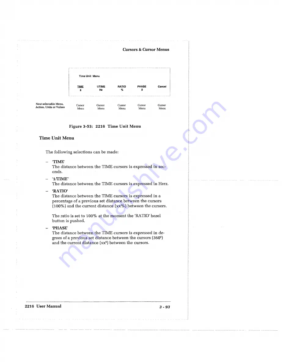
lim e Unit  Menu

TIME

S

1/TSME

Hz

RATIO

%

PHASE

0

Cancel

Cursor

Menu

Cursor

Menu

Cursor

Menu

Cursor

Menu

Cursor

Menu

Figure  3-53:  2216  Time Unit Menu


Time Unit Menu

The following selections can be made:

-   'TIME'

The distance between the TIME cursors is expressed in sec­
onds,

-   T/TIME"

The  distance between the TIME cursors is expressed in Herz,

-   ’RATIO'

The distance between the TIME cursors is expressed in a 
percentage of a previous set distance between the cursors 

(100%) and the current distance (xx%) between the cursors.

The ratio is set to  100%  at the moment the ’RATIO’ bezel 

button is pushed,

-   ’PHASE'

The distance between the TIME cursors is expressed in de­
grees of a previous set  distance between the cursors [360°) 
and the current distance  (xx°) between the cursors.

2216  User Manual

3 - 9 3

Summary of Contents for 2216

Page 1: ...User Manual T ektronix 2216 Four Channel Digital Storage Analog Oscilloscope 070 8903 00 First Printing Febr 1994 Revised 3 14 1994 ...

Page 2: ...olland N V Heerenveen The Netherlands HKO0OOO Tektronix Inc Hong Kong Instruments manufactured for Tektronix by external vendors outside the United States are assigned a two digit alpha code to identify the country of manufacture e g J3 for Japan HK for Hong Kong IL for Israel etc Tektronix Inc P O Box 500 Beaverton OR 97077 Printed and produced in The Netherlands Copyright Tektronix Inc 1994 All ...

Page 3: ...rned to any other locations This warranty shall not apply to any defect failure or damage caused by improper use or inadequate maintenance and care Tektronix shall not be obligated to furnish service under this warranty a to repair damage resulting from attempts by personnel other than Tektronix representa tives to install repair or service the product b to repair damage resulting from improper us...

Page 4: ...illoscope meets the intent of Directive 89 336 EEC for Electromagnetic Compatibility Compliance was demonstrated to the following specifications as listed in the official Journal of the European Communities EN 50081 1 Emissions EN 55011 Radiated EN 60555 2 Conducted EN 50082 1 immunity IEC 801 2 Electrostatic Discharge IEC 801 3 RF Radiated IEC 801 4 Fast Transients IEC 801 5 Surge Draft ...

Page 5: ...ou an overall Product Description of the 2216 oscilloscope operation The next three chapters provide information and instructions to get you started making non storage and storage measurements In the last five chapters of this section the special features of the 2216 will be discussed like using Automated Measurements References Cursors Custom Units and Making Hardcopies The A t A Glance section d...

Page 6: ...lossary I Index M Maintenance P Probes Related Documentation Other documentation for the 2216 oscilloscope includes 2216 Programmers Manual Part Number 070 8905 00 providing programming information for 2216 oscilloscopes with Option 10 GPIB and Option 12 RS 232 C D 2216 SCPI Programmers Manual Part Number 070 8906 00 for 2218 oscilloscopes with Option 10 GPIB and Option 12 RS 232 C 2216 Service Ma...

Page 7: ...tion Storage Functions Menu 1 11 Run Stop Acquisition Measurements M enu 1 13 References References Menu 1 14 Hardcopy Hardcopy M enu 1 15 Setup Controls 1 17 Setup AUTO Feature 1 17 Setup Save Recall Menu 1 18 Setup Utility Menu 1 18 Cursor Feature 1 20 Cursor Position 1 20 SELECT Switch 1 21 Cursors Menu 1 21 CRT Readout 1 22 Flardcopy Interface 1 23 Options 1 23 Standard Accessories 1 23 Certif...

Page 8: ...ements 1 43 Using References 1 51 Using Cursors 1 57 Using Custom Units 1 61 Making Hardcopies 1 67 At A Glance Overview 2 1 At a Glance 2 2 Storage Map 2 3 Vertical System Map 2 4 Horizontal Map Rear Panel M ap 2 8 Menu System 2 7 To Operate a M enu 2 8 Symbols in Menus 2 9 Overview of Menu System 2 10 Menu Summary 2 12 iv Contents ...

Page 9: ...nd Switches 3 21 Triggering 3 25 Trigger Controls Switches and Indicators 3 26 Storage Functions and Menus 3 35 DIGITIZE FUNCTIONS Menu Switch 3 36 RUN STOP MEASURE Menu Switch 3 43 REFS MENU Switch 3 49 HARDCOPY MENU Switch 3 59 Setup Functions and Menus 3 73 UTILITY Menu Switch 3 74 SAVE RECALL Menu Switch 3 84 Cursors and Cursor Menus 3 87 CURSORS MENU Switch 3 88 General Purpose Knob 3 96 SELE...

Page 10: ...ications B l User Interface B l Nominal Traits B 2 Warranted Characteristics B 7 Typical Characteristics B l3 Appendix C Performance Tests C l Vertical Checks C 8 Horizontal Checks C 13 Triggering Checks C l7 Appendix D Algorithms D l Appendix E CRT Readout E l Appendix G Glossary E l Appendix I Index 1 1 Appendix M Maintenance and Repair M l Repackaging for Shipment M 2 Appendix P Probes P 1 Pass...

Page 11: ...eform Display 1 28 Figure 1 18 Example of a Alternate Sweep Display 1 31 Figure 1 19 Storage Section 1 46 Figure 1 20 2216 Measurement Menu 1 47 Figure 1 21 2216 Select Measurement Menu 1 48 Figure 1 22 2216 Measurement Unit Menu 1 49 Figure l 22a Middle Reference Levels Influence on a Measurement 1 50 Figure 1 23 2216 Set Reference Level Menu 1 50 Figure 1 24 Aliasing 1 41 Figure 1 25 2216 Refere...

Page 12: ...3 12 2216 Slow Display Mode M enu 3 41 Figure 3 13 2216 Limit Test Setup M enu 3 42 Figure 3 14 2216 Storage Functions and Menu Switches 3 43 Figure 3 15 2216 Measurements Menu 3 44 Figure 3 16 2216 Select Measurement M enu 3 45 Figure 3 17 2216 Set Measurement Reference Level Menu 3 47 Figure 3 18 2216 Measurement Unit M enu 3 48 Figure 3 19 2216 Define Custom Unit M enu 3 48 Figure 3 20 2216 Sto...

Page 13: ...up Utility User Compensation Menu 3 83 Figure 3 47 2216 Setup Save Recall Menu 3 84 Figure 3 48 2216 Setup Edit Name Menu 3 85 Figure 3 49 Cursors Menu Switch GPK Knob SELECT Knob SHIFT Function Switch 3 87 Figure 3 49a 2216 Cursors M enu 3 89 Figure 3 50 2216 Cursors Function Menu 3 90 Figure 3 51 2216 Unit M enu 3 91 Figure 3 52 2216 Voltage Unit Menu 3 92 Figure 3 53 2216 Time Unit Menu 3 93 Fi...

Page 14: ...X Contents ...

Page 15: ...red channels 16384 point record length per channel 131072 point optional Auto Set up CRT readout as well as front panel LED indicators Cursor measurement O Advanced Measurement Functions DC to 60 MHz Analog non storage bandwidth D 20 Megasamples second maximum digitizing rate C J Menu operation blended with the traditional horizontal vertical and triggering knobs Parallel Printer Interface Centron...

Page 16: ...ween probe common and earth ground Symbols and Terms These two terms appear in manuals CAUTiO l statements identify conditions or practices that could result in damage to the equipment or other property jhafimn statements identify conditions or practices that could result in personal injury or loss of live These two terms appear on equipment CAUTION indicates a personal injury hazard not immedi at...

Page 17: ...be tween either supply conductor and ground A protective ground connection through the grounding conductor in the power cord is essential for safe system operation Grounding the Product This product is grounded through the grounding conductor of the power cord To avoid electric shock plug the power cord into a properly wired receptacle where earth ground has been verified by a qualified service pe...

Page 18: ...nstrument and in the Options and Accessories section Do Not Operate in an Explosive Atmosphere This product provides no explosion protection from static dis charges or arcing components Do not operate this product in an atmosphere of explosive gasses Do Not Remove Covers or Panels To avoid personal injury do not operate the instrument without covers and panels Electric Overload Never apply to a co...

Page 19: ...erations pouvant entrainer la deterioration de 1 appareil ou de tout autre equipment Les paragraphes intitules AVERTISSEMENT indiquent les circonstances dangereu ses pour l utilisateur danger de mort ou risque de blessure Static Sensitive Devices Composants sensible a statique Termes repereres graves sur 1 appareil CAUTION ATTENTION ce mot identifie les zones de risque non immediatement perceptibl...

Page 20: ... masse En cas de coupure de la connexion de masse tous les elements conducteurs accessible y compris boutons et commandes apparissant isolants peuvent provoquer un choc electrique Utuliser le cordon d alimentation approprie N utiliser que le cordon d alimentation et la prise recommandes pour votre appareil Utiliser un cordon d alimentationen parfait etat Seul un personnel qualifie peut proc6der a ...

Page 21: ...e rear of this manual Step 2 Leave space for cooling Do this by verifying that the air intake and exhaust holes ou the sides of the cabinet are free of any airflow obstructions Leave at least 5 cm 2 inches free on each side Figure ii Rear Panel Controls Used at Start Up NOTE To avoid electrical shock be sure that the power cord is discon nected from the instrument before checking the fuse The 2216...

Page 22: ...l power connector to the power system see Figure ii Figure iii Partial 2216 Front Panel Controls Used at Start up Step 5 Press the POWER button Observe that the POWER ON indicator located above the button comes on see Figure iii After a few seconds a trace appears on the CRT screen and the instrument is ready to make measure ments Step 6 Press the Setup AUTO switch to obtain an optimized dis play ...

Page 23: ...e 2216 are discussed in separate chapters The Tutorial section is split up in the following separate chap ters Product Description page 1 2 Initial Setup page 1 24 Probe Compensation page 1 25 Making Measurements page 1 27 Using X Y Display Mode page 1 33 Using Single Sweep Operation page 1 35 Observing Aliases 1 41 Cf Using Automated Measurements in Store Mode page 1 43 Using References in Store ...

Page 24: ...perated blended with the traditional horizon tal vertical and triggering knobs The 16KB record length in the standard 2216 can be extended to 128KB with Option 1M implemented The 2216 can be made a programmable oscilloscope with Option 10 GPIB and or Option 12 RS232 implemented The following topics will be discussed Display System Vertical System Horizontal System Triggering System Storage System ...

Page 25: ...douts measurement re suits and menus In the SCREEN section of the front panel the display controls are situated see Figure 1 1 The POWER switch turns the power ON or OFF At power on the ON led lights The INTENSITY control adjusts the brightness of the trace or the readout With the TRACE READOUT toggle switch you can select to adjust 2216 User Manual 1 3 ...

Page 26: ...r division All vertical channels can be se lected separately with the CHI 2 3 4 channel switches One vertical channel at a time can be made the active channel and can be operated by the following controls The CH REF OFF switch turns off the active channel or the active reference The vertical POSITION control positions the display of the active channel The INVERT switch inverts the signal of the ac...

Page 27: ... X Y Using CH 1 2 and CH 3 4 simultaneously turns the 2216 into a dual channel differential oscilloscope X Y Mode In non store mode CH 1 or CH1 2 can be operated as the X axis and CH 2 CH 3 CH 4 and CH3 4 as the Y axis see also page 1 33 In store mode the X axis and the Y axis signals can be se lected in the XY Menu see also page 1 34 2216 User Manual 1 5 ...

Page 28: ... is expressed in seconds per division Figure 1 3 2216 Horizontal Systen Non Store Mode In non store mode STORE led off the calibrated horizontal sweep speeds SEC DIV range from 0 5 s to 0 05 ps per division The VARiable SEC DIV control may be used to increase the ana log sweep time per division by a factor up to 2 5 times of the cali brated time per division as set by the SEC DIV switch 1 6 Tutori...

Page 29: ...fy Menu Alternate OS OFF Fit To Scr xIO xSO Figure 1 4 2216 Magnify Menu Pressing successively the SHIFT button and the MAG MENU button shows the Magnify Menu see Figure 1 4 Selections from the menu can be made with the bezel buttons as indicated in the readout Selecting Alternate ON will alternately display an unmagni fied sweep and a sweep with the selected magnification factor Selecting the xIO...

Page 30: ...nel controls in non store mode see Figure 1 5 except if the AUX input is selected for TRIGGER in the Setup Configuration Menu In store mode the additional pre trigger selection is defined in the Trigger Position Menu sub menu of the Functions Menu Figure 1 5 2216 Triggering System Section 1 8 Tutorial ...

Page 31: ...auto trigger is generated and the sweep free runs With sweep triggers of 20 Hz and more the sweep behaves as normally triggered NORMal triggering In the absence of a trigger signal no auto trigger is generated and the sweep can only be started with a trigger from the trigger circuit Single sweep SINGLE triggering One single sweep is started by a trigger pulse which is generated after the RE SET bu...

Page 32: ...LEVEL HOLDOFF control determines where on the edge of the signal the trigger point occurs when the H O LEVEL switch is in the LEVEL position Pressing the FORCE trigger button a sweep starts immedi ately regardless of any other trigger condition In single sweep operation SINGLE the trigger circuit is reset to accept a trigger event by pressing the RESET button After receiving a trigger pulse the ti...

Page 33: ... in the STORAGE section of the front panel Storage menus can be dis played by first pressing the SHIFT button and successively the required menu button Digitize Function Storage Functions Menu The 2216 can be operated as an analog or a digitizing oscillo scope Pressing the DIGITIZE FUNCTIONS button toggles the 2216 between the analog and storage inode In store mode the STORE LED lights and analog ...

Page 34: ...ng record option implemented Option 1M the record length selection list is extended to 32 KB 64 KB and 128 KB The acquisition Clock Source Menu to select the internal clock INTERN or the external clock AUX IN RECORD or AUX IN SLOW The Storage Function Slow Display Mode Menu to select a ROLL or SCAN display mode at slow acquisition rates In Average acquisition mode setting the 2216 calculates an av...

Page 35: ...easurements Menu The following items and sub menus can be selected Pressing the Select bezel button the Select Measurement Menu will be selected The following measurements can be selected Minimum Value Maximum Value Peak to Peak Period Frequency Duty Cycle Duty Cycle Power Pressing the Remove bezel button removes the measure ment The Gating bezel button selects whether measurements are performed u...

Page 36: ...isplay Delete Rename Position Mode Figure 1 9 2216 References Menu The following items and sub menus can be selected Pressing the Save bezel button in the Refs Menu causes the active waveform to be saved in the reference memory A maximum of 64 KB reference memory is available which can be used for storing a maximum of 16 waveforms Pressing the Display bezel button the Reference Display Menu is sho...

Page 37: ...Menu During hardcopy a PRN message is shown in the readout Pressing the HARDCOPY MENU switch again stops the print action Pressing the SHIFT and the HARDCOPY MENU button succes sively the Hardcopy Menu is shown see Figure 1 10 Hardcopy Menu Mods RECORD Format THINKJET Port CENTR Setup Layout Figure 1 10 2216 Hardcopy Menu In the Hardcopy Menu the following sxxh menus can be selected Pressing the M...

Page 38: ...dcopy Port Menu is se lected In the Hardcopy Port Menu a sub menu to setup the RS232 parameters or a hardcopy output port is se lected CENTRONICS GPIB Option 10 only RS232 Option 12 only Hardcopy Setup RS232 Menu In the Hardcopy Setup RS232 Menu the RS232 interface parameters are set that are used when making a hardcopy via the RS232 port Pressing the Setup Layout button the Hardcopy Setup Lay out...

Page 39: ...ture The 2216 has a Setup AUTO feature implemented to get a display of an unknown signal by pressing just one front panel button Pressing the Setup AUTO button the 2216 Setup AUTO feature sets automatically the following front panel functions to display an unknown waveform Vertical scaling Horizontal scaling Triggering Display controls A stable automatically triggered display of the waveforms ap p...

Page 40: ...he Setup Save Recall Menu the Factory Default Setup can be selected for recall Five User Settable Setups can be selected for save recall and editing of the label If the 2216 is switched off the settings of the momentary instrument setup are saved and will be used at start up Setup Utility Menu Pressing the Setup UTILITY button shows the Utility Menu on the screen see Figure 1 13 In the UTILITY men...

Page 41: ...ion interface are defined if GPIB is used to remotely control the instru ment Press the Progr RS232 button on menu page 2 to show the Programmable RS232 Menu In the Programmable RS232 Menu the settings of the optional RS232 communication interface are defined if RS232 is used to remotely control the instrument Press the Hardcopy RS232 button on menu page 2 to show the Hardcopy RS232 Menu In the Ha...

Page 42: ...nction Cursors should be positioned on the required measurement points in a waveform The crt readouts indicate that the distance be tween the cursors is expressed as a voltage difference AV a RATIO expressed in of a previously set distance between the cursors 100 a timing difference AT a reciprocal time difference approximate frequency 1 AT a PHASE expressed in 0 s of a previously set distance bet...

Page 43: ...de TIME cursors which results in vertical lines in Y t mode and squares in X Y mode PAIRED cursors Press PAIRED if you want to observe the readout of the TIME cursors and the readout of the Voltage difference between the crossing points of the TIME cursors and the active signal Pressing the Unit button will select the Cursor Unit Menu This menu is dependent on the selected Cursor Function There ar...

Page 44: ...ode one cursor is avail able The cursor can be positioned with the GPK control The distance between the trigger point and the cursor is measured TIME Cursor Function or the distance be tween ground level and the cursor VOLTAGE Cursor Function NOTE To ensure maximum accuracy for the VOLTAGE Cursor Function the User Cal in the Setup Utility Menu should be performed CRT Readout The CRT readout of the...

Page 45: ... for the 2216 GPIB IEEE 488 2 communication interface 2216 Option 10 RS 232 C communication interface control 2216 Option 12 Long record length of 128 KB per channel user programmable 2216 Option 1M Standard Accessories The following accessories will be shipped with each 2216 Two Tektronix P6109B probes lOx attenuator 2216 User Manual 2216 Quick Reference Power cord as ordered Certification The 22...

Page 46: ... the POWER switch ON and let the instrument warm up 20 minutes is recommended for best accu racy NOTE At power up the instrument will return to the status before power down Step 4 Connect the probe s or signal cable s with the signal s to be measured to the vertical input connector s Step 3 Use the CH 1 CH 2 CH 3 and CH 4 select buttons to display the channel of interest Step 6 Press the Setup AUT...

Page 47: ...tton Step 5 Check the square wave display for overshoot and rolloff see Figure 1 16 If necessary use a small bladed screwdriver or alignment tool to adjust the compensa tion on the probe for a square front comer on the square wave displayed Step 6 Remove the probe tip from the PROBE ADJUST connec tor Step 7 Connect the probe tip of CH 2 to the PROBE ADJUST connector and the probe ground lead to sc...

Page 48: ... tWER COMPENSATED OVERSHOOT UNDER COMPENSATED ROLLOFF Figure 1 16 Probe Compensation NOTE Refer to instruction manual supplied with the probe for more complete information on the probe accessories and probe compensation 1 26 Tutorial ...

Page 49: ...lp yon make measurements with the 2216 oscilloscope in Non Store mode as well in Store mode The follow ing topics will be discussed Using Unmagnified Sweep Displays page 1 28 Using Magnified Alternate Sweep Displays page 1 31 2216 User Manual 1 27 ...

Page 50: ...ay an un magnified sweep see Figure 1 17 Figure 1 17 Example of a Waveform Display Step 1 Switch the 2216 on press CH 1 button to on and obtain a display on CH 1 NOTE You may use CH 2 CH 3 or CH 4 or a combination of channels as well Step 2 Using a lOx probe or a properly terminated coaxial cable apply a signal to the CHI input connector The signal source output impedance determines the terminatio...

Page 51: ...r a stable triggered display Step 6 Set the SEC DIV switch for the desired number of cycles of the displayed signal Then adjust the FOCUS control for the best defined display Store Mode Displays The conditions under which a waveform is acquired in store mode for display are set with the usual front panel control selections and the settings in the storage menus The difference with the non store set...

Page 52: ...OLL SCAN mode except in SINGLE Sweep In RECORD and ROLL SCAN mode not in SINGLE Sweep you may use the following procedure to display a signal on the screen Step 1 Switch the 2216 on Step 2 Press the CH 1 button to on Apply the signal to be dis played to the CH 1 inpnt connector Step 3 Press the AUTO Setup button Step 4 Press the DIGITIZE FIJNCTION button to the ON state STORE on if not in store mo...

Page 53: ...rnate Sweep Display You can use the following procedure to display the magnified signal see Figure 1 18 Step 1 Switch the 2216 on Step 2 Set the SEC DIV switch for a sweep speed that permits you to select the area to be magnified Step 3 Adjust the Horizontal POSITION control for precise posi tioning of the area to be magnified to the center crt grati cule division The actual magnified portion on e...

Page 54: ...he bezel buttons the magnification factor FIT TO SCREEN xlO x50 NOTE The magnified sweep rate is displayed in the crt readout Step 6 If Alternate Magnify is needed to display the magnified sweep and the unmagnified sweep on the crt screen alter nately press the Alternate bezel button to select ON Step 7 Adjust the vertical POSITION control and the TRACE SEParation control as required to display th...

Page 55: ...he VOLTS DIV and the POSITION to a proper display Step 3 Rotate the TRACE INTENSITY control fully counter clockwise Step 4 Toggle the X Y MENU switch to X Y X Y LED on Step 5 Increase the INTENSITY until the display is visible NOTE The display obtained when sinusoidal signals are applied to the X and Y axis is called a Lissajous figure This display is commonly used to compare the frequency and pha...

Page 56: ...e CH 1 through CH 4 Ref 1 through Ref 16 or NONE Step 5 Press the channel and the reference select buttons to dis play the Xl Yl X2 and Y2 waveforms Step 6 Define with the SEC DIV switch the sample rate for the XY signal if the Clock Source in the Function Menu is set to INTERN NOTE With an external clock signal to the AUX input on the rearpanel and the Clock Source in the Function Menu set to AUX...

Page 57: ... signal and make CH 1 the active channel CH 1 LED is on Apply a test signal to the CH 1 input connector to set the VOLTS DIV and the trigger LEVEL control correctly NOTE For random signals set the triggerLEVEL control to trigger the sweep on a signal that is approximately the same amplitude as the random signal Step 3 Set the VOLTS DIV switch and adjust the vertical POSI TION control to display th...

Page 58: ...been triggered and the sweep is completed the sweep logic circuit is locked out Another sweep cannot be generated until the single sweep RESET button is pressed again to set the sweep to the READY state Step 7 Disconnect the test signal from the CHI input Apply the random signal to the CEI1 input and press the RESET button to set the sweep to the READY state Step 8 When the random trigger pulse oc...

Page 59: ... Press the DIGITIZE switch to activate the store mode Step 2 Define the trigger point in the Trigger Position Menu sub menu of the Functions Menu as needed for your measure ment Step 3 Press the CH 1 button to display CH 1 and make GH 1 the active channel Step 4 Apply a test signal to the GH 1 input for setting the trigger LEVEL control NOTE For random signals set the trigger LEVEL control to trig...

Page 60: ...ready to start the acquisition when the trigger occurs When the random trigger pulse occurs the acquisition will be started and one single acquisition will be dis played on the crt screen Step 11 When the single sweep has been triggered and completed another acquisition cannot be started until the RESET button is pressed again to rearm the acquisition circuit Single Sweep in ROLL SCANMode In SINGL...

Page 61: ...channel Step 4 Apply a test signal to the CH 1 input for setting the trigger LEVEL control NOTE For random signals set the trigger LEVEL control to trigger the sweep on a signal that is approximately the same amplitude as the random signal Step 5 Set the VOLTS DIV switch and adjust the vertical POSITION control to display the waveform correctly within the graticule area Step 6 Toggle the trigger M...

Page 62: ...to set the acquisition system to the READY state The trace starts rolling from the right to the left of the screen in ROLL mode or a constant refresh of data is vis ible moving from left to right in SCAN mode Until the trigger event occurs the READY light will be on to show that the oscilloscope is armed and ready to start the acqui sition when the trigger occurs When after the pre trigger time th...

Page 63: ...veform Due to Aliasing Figure 1 24 Aliasing In digital sampling a more accurate reproduction of a signal is pos sible when more samples of the signal are obtained The 2216 sam ples 4000 times across the 10 horizontal divisions of the graticule A sine wave spread across the full screen will be sampled 4000 times NOTE With 512 points recordlength the 2216 samples 400 times across 10 horizontal divis...

Page 64: ...ll reproduce what appears to be a correct display when in fact it is only related to the input signal by some multiple or part of a mul tiple of the input signal This type of display is one type of alias see Figure 1 24 The sampling rate is controlled by the SEC DIV switch and it de creases when the SEC DIV switch is set to slower settings Whenever the SEC DIV switch is set so that the input signa...

Page 65: ...if Gating ON is se lected in the Measurement Menu The 2216 provides 15 different automatic measurements see Table 1 1 The readout of the measurement result is on the right side of the crt screen One automatically updated measurement can be displayed at a time NOTE To ensure maximum vertical accuracy in the measurement the User Compensation function in the Setup Utility Menu should he performed bef...

Page 66: ...rst cycle in the gated region Cycle Power Power measurement The arithimc mean over the first cycle of the active waveform or the first cycle in the gated region over the product of both waveforms T T Cycle RMS Voltage measurement The True Root Mean Square voltage over the first cycle in the wave form or the first cycle in the gated region fli Frequency Timing measurement for the first cycle in the...

Page 67: ... and the minimum ampli tude measured over the entire waveform record or the gated region Peak to Peak Max Value Min Value rtf Period Timing measurement Time it takes for the first complete cycle to happen in the waveform or gated region The reciprocal of frequency Meas ured in seconds JLI Positive Duty Cycle Timing measurement for the first cycle in the waveform or the gated region The ratio of th...

Page 68: ...ition in Record and in Roll Scan mode Step 1 Acquire a waveform Step 2 Pressing the RUN STOP button while in RECORD mode causes the current display to be stopped immediately and the display is not updated STOP appears in the acquisi tion status field of the readout Step 3 Pressing the RUN STOP button again restarts the acquisi tion Step 4 Pressing the RUN STOP button while in ROLL SCAN mode causes...

Page 69: ...ursors are displayed to de fine a gate in which the measurement action is taking place The measurement gate the region between the two cursors can be defined with the GPK control and the SE LECT switch Step 3 Press the Select bezel button to display the Select Meas urement Menu see Figure 1 21 Step 4 Select the measurement type as indicated in the Select Measurement menu Selecting another measurem...

Page 70: ...e can be used to de fine the unit of measure Step 1 Press the SHIFT button and the RUN STOP MEASURE button to display the Measurement Menu Figure 1 20 Step 2 Press the Unit bezel button in the Measurement Menu to display the Measurement Unit Menu see Figure 1 22 Step 3 Press the Unit bezel button in the Measurement Unit Menu to V Volts or GUST Custom unit Step 4 If COST is selected the custom unit...

Page 71: ...ne a mid reference level in the 2216 for a waveform to be measured at a different mid reference level than the default level The mid reference level is used to determine the duration of a pe riod of a waveform see Figure 1 22a The mid reference level can be defined as a percentage of the peak to peak amplitude of the signal or as an absolute voltage value The 2216 uses the mid reference level for ...

Page 72: ... Press the li bezel button to select the menu line Step 4 Press the or bezel button to select the or the V reference level unit Step 5 Press the U bezel button again to select the mid ref level line Step 6 Define the desired mid ref level Mid Ref Mantisse1 and Exponent with the GPK control NOTE To reinstall the 50 0 V mid refposition press the Set to 50 set to 0 V bezel button Step 7 Press the Pre...

Page 73: ...aveform as a reference via the Refs Menu see Figure 1 26 Deleting a reference from the reference memory Figure 1 27 Renaming a reference via the Rename Reference Menu Figure 1 28 Positioning a reference on the screen via the position controls and the Refs Position Menu Figure 1 30 REF3 200mV SOOps More REF2 REF3 REFS REF 11 1 of 4 Figure 1 25 2216 Reference Readout Menu Refs Menu Save to REF1 Save...

Page 74: ... References Position Mode menu de fines the effect of these controls NOTE The vertical POSITION control does not affect the data stored in the reference memory but it does set the vertical position of the reference at the time it is displayed Step 4 To remove an active reference from the screen press the CH REF OFF front panel button Step 5 The Reference display can be expanded horizontally along ...

Page 75: ...full Reference waveforms remain saved in a battery backuped memory when the 2216 is turned off Deleting a Reference To delete a reference from memory via the Reference Menu use the following procedure Step 1 Press the SHIFT and REFS MENU buttons successively to display the References Menu Step 2 Press the Delete bezel button to display the Delete from Memory menu see Figure 1 27 Step 3 Select with...

Page 76: ...ting reference use the following proce dure Step 1 Press the SHIFT and REFS MENU buttons successively to display the References Menu Step 2 Press the Rename bezel button to display the Rename Reference 1menu Step 3 Select with Previous Ref or Next Ref bezel button the reference to be renamed Step 4 Press the Edit Name bezel button to display the REFS Edit Name menu see Figure 1 29 Step 5 Toggle th...

Page 77: ...ame menu Defining Positioning of References The horizontal positioning of references and the function of the horizontal position control can be defined in the References Posi tion Mode Menu see Figure 1 30 REFS Position Mode Menu H Lock Align NONE Trig Align Rec Previous Menu Next selectable Menu H Lock Refs Action Units or Values Menu Menu Figure 1 30 2216 Reference Position Mode Menu To change t...

Page 78: ...eform The references can be positioned independently by making the specific reference the active waveform In REFS changing the horizontal POSITION control will position all channels simultaneously while a channel is the active waveform If a reference is made the active waveform all references will be positioned simultane ously In ALL the horizontal POSITION controls all waveforms simultaneously re...

Page 79: ...HIFT and CURSOR MENU button successively the Cursors Menu is shown and the cursors can be defined In this section we will discuss Cursors Defining Cursors page 1 59 Cursors Cursor Types The 2216 has basically the following cursor types VOLTAGE cursors horizontal bars measure vertical parameters typically volts TIME cursors vertical bars measure horizontal parameters typically time or frequency PAI...

Page 80: ...rtical cursor and the trigger point is displayed in the readout in s or Hz or the distance between the horizontal cursor and ground level of the active waveform is displayed in the readout in Volts or custom units NOTE For maximum vertical accuracy perform User Cal In the Setup Utility Menu before making measurements in SINGLE mode Cursor Units Several cursor measurement units can be selected depe...

Page 81: ...tion TIME Unit s Define Gust Scroti OFF ON Mode DEUM Next selectable Menu Action Units or Values Cursor Function Menu Cursor Unit Menu Define Custom Unit Menu ON Cursor Mode Menu Figure 1 32 Cursors Menu TIME Defining Cursors The following items must be defined in the Cursors Menu see Fig ure 1 31 and Figure 1 32 and sub menus before they can be used for a measurement Cursor Function Cursor Unit C...

Page 82: ...nit Menu TIME s 1 TIME Hz RATIO or PHASE Select in the Voltage Unit Menu VOLT V CUSTOM custom unit or RATIO If CUSTOM is selected define the custom unit in the De fine Custom Unit Menu see page 1 61 Press the Mode bezel button in the Cursor Menu to select the Cursor Mode Menu Press the DELTA TRACK or SINGLE absolute value bezel button to select the mode Press the Scroll bezel button to ON or OFF a...

Page 83: ...Y A 1 0log VI 8 Define Custom Unit Menu formuia A value B value unit name Y A VI B 1 23 E 1 1 23E 1 R P M Jt Previous Next Formula Formuia Previous Menu Figure 1 33 2216 Define Custom Unit Menu The parameters and constant factors in these formulas can be de fined as follows Y is the custom value to be displayed Vl is the value from the uncorrected measurement result The A value and B value are use...

Page 84: ... use the following procedure Step 1 Press the SHIFT and CURSORS MENU buttons succes sively to display the Cursors Menu see Figure 1 31 Step 2 Press the Function bezel button to select the VOLTAGE or PAIRED cursors as desired for the measurement Step 3 Press the Unit bezel button to select the Cursor Voltage Unit Menu Step 4 Press the GUST bezel button Step 5 Press the Define Custom bezel button to...

Page 85: ...Figure 1 34 Step 12 Toggle the It bezel button to the unit name line see Figure 1 35 Step 13 Toggle with the Select Position bezel button to the de sired position Step 14 Press the Char bezel button and select with the GPK con trol the character to be applied Step 15 Toggle the Select Position bezel button to the next posi tion and repeat step 16 etc Step 16 Press the Previous Menu bezel button to...

Page 86: ...om Units Define Custom Unit Menu formula A value B value unit name Y A 4VI B 1 23 E 12 2 50 E 0 R P M I Select Char Position R 1 Previous Menu Figure 1 35 2216 Define Custom Unit Menu Unit name line 1 64 Tutorial ...

Page 87: ...converted to a voltage signal The custom unit calcula tion formulas can be used to compensate the current to voltage con version You can use a Tektronix Current Probe in this application for exam ple a P6021 with a current probe amplifier Tektronix type 134 to measure the current Id through the BUT Using a P6021 the output sensitivity of the current probe amplifier Tektronix Current Probe Amplifie...

Page 88: ... perform a power measurement use the following procedure Step 1 Connect a voltage probe P6109B to CH 1 Step 2 Connect a P6021 current probe together with the 134 cur rent probe amplifier to CH 2 and set the CH 2 VOLTS DIV to 50 mV DIV Step 3 Select in the Select Measurement Menu the Cycle Power measurement see page 1 45 Step 4 Select CH 2 as the Power to in the Cycle Power sub menu Step 5 Make CH ...

Page 89: ...el A 2216 Option 10 GPIB and 2216 Option 12 RS232 may also use the GPIB Interface connector or the Serial Communication Interface RS232 connector as the hardcopy output Before making a hardcopy be sure that the correct selections are made in the Hardcopy Menu and sub menus Figure 1 38 The following will be discussed Start and Stop a hardcopy on a Plotter Printer page 1 68 Selecting a Hardcopy Mode...

Page 90: ... a PRN message on the screen Press the HARDCOPY MENU button again to stop the print action Press the SHIFT and the HARDCOPY MENU button successively to display the Hardcopy Menu see Figure 1 38 Hardcopy Menu Mode RECORD Format TH1NKJET Port CENTR Setup Layout Figure 1 38 2216 Hardcopy Menu Select and define respectively the Hardcopy Mode Menu the Hard copy Format Menu the Hardcopy Port Menu and th...

Page 91: ...ART mode STATUS mode Hardcopy Mode Menu RECORD CHART STATUS j Previous j Menu j J Figure l 39a 2216 Hardcopy Mode Menu Press the bezel button concerned to select a hardcopy mode The record and chart mode selection automatically shows the Hard copy Record Mode Menu Figure l 39b or resp the Hardcopy Chart Mode Menu Figure l 39e Hardcopy Rec Mode Menu SCREEN FULL BETWEEN Previous COPY RECORD CURSORS ...

Page 92: ...inted Hardcopy Chart Mode Menu Time DSv Previous 0 1 s Mena Figure l 39c 2216 Hardcopy CHART Mode Menu In CHART mode a chart recorder is emulated by the 2216 printer driver for continuous printing of a ROLL SCAN acquisition The selection of the chart recorder timebase is defined in theHardcopy Chart Mode Menu Figure l 39c The timebase is set by the GPK control NOTE In CHART mode you can use the EP...

Page 93: ... be selected HPGL THINKJET EPSON FX DESKJET EPSON LQ LASERJET Use the following procedure to select a format Step 1 Press the SHIFT and the HARDCOPY MENUbutton suc cessively to display the Hardcopy Menu Figure 1 38 Step 2 Press the Format bezel button in the Hardcopy Menu to display the Hardcopy Format Menu Step 3 Select the hardcopy format with the appropriate bezel button Step 4 Release the beze...

Page 94: ...ers can be set size of the hardcopy non HPGL only number of pens HPGL only used by the plotter graticule representation on the hardcopy time date user note text Use the following procedure to setup a hardcopy layout Step 1 Press the SHIFT and the HARDCOPY MENU button suc cessively to display the Hardcopy Menu Figure 1 38 Step 2 Press the Setup Layout bezel button in the Hardcopy Menu to display th...

Page 95: ...llowing procedure to change a user note text Step 1 Press the SHIFT and the HARDCOPY MENU button suc cessively to display the Hardcopy Menu Figure 1 38 Step 2 Press the Setup Layout bezel button in the Hardcopy Menu to display the Hardcopy Layout Menu Stop 3 Select the user note line Step 4 Press the Edit Note bezel button in the Hardcopy Layout Menu to display the Hardcopy Layout Edit Note sub me...

Page 96: ...cter in the text Step 9 To delete a character select it with the Select Position bezel button and press Delete Char to delete the charac ter from the text Step 10 Press the Previous Menu bezel button to return to the Hardcopy Menu or press GLEAR MENU to leave the Hard copy Layout Edit Note Menu 1 74 Tutorial ...

Page 97: ...or Option 10 12 You can select the fol lowing hardcopy output ports CENTRonics a parallel printer plotter interface output port connector GPIB a GPIB communication interface output port connector RS232 a RS232 communication interface output port connector By pressing the HC Setup RS232 bezel button the Hard Copy Setup RS232 menu is displayed In the Hardcopy Setup RS232 menu the settings of the RS2...

Page 98: ... 3 Select the CENTR GPIB or RS232 hardcopy port with the appropriate bezel button Step 4 Press the Previous Menu bezel button to return to the Hardcopy Menu or press CLEAR MENU to leave the Hard copy Port Menu 1 76 Tutorial ...

Page 99: ...2 u Previous Menu Figure 1 45 2216 Hardcopy Setup RS232 Menu The following parameters can be defined Baudrate Handshaking mode Parity Number of Stopbits Use the following procedure to define the settings in the HC Setup RS232 Menu Step 1 Press the SHIFT and the HARDCOPY MENU button suc cessively to display the Hardcopy Menu Figure 1 38 Step 2 Press the Port bezel button in the Hardcopy Menu to dis...

Page 100: ...lect a parameter line Step 5 Press the or bezel buttons to select the desired RS232 parameter on the parameter line etc Step 6 Press the Previous Menu bezel button to return to the Hardcopy Menu or press CLEAR MENU to leave the Hard copy Menu 1 78 Tutorial ...

Page 101: ...how the locations and purposes of the various knobs and buttons The VERTICAL system map shows the locations and purposes of the various knobs buttons and connectors in the VERTICAL section The TRIGGER and HORIZONTAL system map shows the locations and purposes of the various knobs and buttons in the TRIGGER and HORIZONTAL section The Hear Panel Map shows the locations and purposes of the various pa...

Page 102: ...Map CRT Readout TRACE READOUT Area Intensity Switch TRACE READOUT INTENSITY Control BEAMFIND Switch Area page 3 5 Area page 1 22 Or MENU Text Selection Switches page 3 6 Switch page 3 5 Area page 1 22 3 6 2 2 At a Glance ...

Page 103: ...4 3 49 Setup AUTO Switch page 1 17 SHIFT Function onloff Switch page 2 9 3 96 General Purpose Selection Switch page 3 96 General Purpose Knob GPK page 3 96 Store Mode on Indicator page 1 11 3 36 Hardcopy Function Switch page 1 15 SHIFT HARDCOPY Menu page 1 15 3 59 Setup Utility Menu Switch page 1 18 3 74 Shift Function on Indicator page 3 96 Setup Save Recall Menu page 1 18 3 83 CURSORS Measuremen...

Page 104: ...rtical Switching Mode Selection Switch page 1 5 3 12 Active Channel VARiable Scale Controls page 1 4 3 13 H fCK Mode Indicator page 1 5 3 15 X Y Mode SHIFT X Y Menu Switch page 1 5 3 15 Q XM ind page 3 17 Probe Adjust Channel Active Active Active Active page 3 Activating Channel Channel Channel Channel BANSl 1 Switches Switch Off COUPLING INVERT WIDTH LIMIT page 1 4 Switch I Switch Switch Switch C...

Page 105: ...Trigger Scale Selection Switch page 1 6 3 23 Magnifier on off Switch page 3 21 1 7 SHIFT Alternate Menu page 1 7 3 22 Horizontal MODE Scale Selection Controls Switch page 1 6 page 3 29 3 24 Trigger LEVEL Holdoff Select Switch page 1 10 3 26 FORCE Trigger Switch page 1 10 3 29 Sweep Triggered Indicator page 3 27 Trigger SLOPE Indicators page 3 27 Trigger SLOPE Selection Switch page 1 10 3 27 Trigge...

Page 106: ... Port Centronics Compatible page 3 63 3 68 3 99 1 External Clock Store Mode or Z Axis Analog Mode and 2 External Trigger IEEE STD 488 PORT Optional page 3 79 3 66 3 100 RS 232 C DTE PORT Optional page 3 81 3 101 Fuse Holder page 3 98 Power Cord Receptacle page 3 98 2 6 At a Glance ...

Page 107: ...s general information about 2216 menus such as Operating a Menu page 2 8 Symbols in menus page 2 9 Overview of Menus page 2 10 Menu Summary page 2 12 Horizontal Magnify Menu page 2 13 a Storage Functions Menus page 2 14 a Measurements Menus page 2 15 a References Menus page 2 16 Hardcopy Menus page 2 17 Setup Utility Menus page 2 18 a Setup Save Recall Menus page 2 19 Cursor Menus page 2 20 D X Y ...

Page 108: ...e SHIFT button prior to selecting a blue1menu indicated at the bottom of afront panel button 3 PrGSS a Beze button to select a sub menu or an item 2 Press the Front Panel Button Menu Readout to select the Menu to be displayed 2 8 At a Glance ...

Page 109: ...ated direction Underlined Dual Underlined I 1 Previous Menu Cancel SHIFT Indicates that the item is currently selected Indicates that the item is currently selected and active For References only Indicates that pressing the bezel button the brackets will appear together with the GPK Gen eral Purpose Knob symbol and that the value can he changed by rotating the GPK Indicates that pressing the bezel...

Page 110: ...ond Waveform Menu page 1 48 3 45 Set Reference Levels Menu page 1 13 1 49 3 46 Measurement Unit Menu page 1 13 1 48 3 47 Custom Unit Menu page 1 13 1 61 3 48 References Menus Reference Readout page 1 14 1 52 3 51 References Menu page 1 14 1 51 52 Reference Display Menu page 1 14 1 52 3 53 Delete References Menu page 1 14 1 53 3 54 Rename References Menu page 1 14 1 54 3 55 References Position Mode...

Page 111: ...mable GPIB Menu page 1 19 3 80 Setup Utility Programmable RS232 Menu pagel 19 3 82 Setup Utility User Calibration Menu 1 19 3 79 Setup Save Recall Menus Setup Save Recall Menu see page 1 18 3 84 Setup Edit Name Menu see page 3 85 Cursors Menus Cursors Menu see page 1 21 1 59 3 88 Cursors Function Menu 3 90 Cursors Unit Menu see page 1 60 3 91 Cursors Voltage Unit Menu see page 3 92 Cursors Time Un...

Page 112: ...uence of pressing front panel buttons and bezel buttons is indicated to select a menu The 2216 has the following menu groups Magnify Menu Functions Menus Measurements Menus References Menus Hardcopy Menus Setup Utility Menus Setup Save Recall Menu Cursors Menus X Y Menu 2 12 At a Glance ...

Page 113: ...Menu System Horizontal Magnify Menu To show this menu Press these front panel buttons and bezel buttons Magnify Menu H B 1 2216 User Manual 2 13 ...

Page 114: ... Storage Functions Menu Trigger Position Menu Record Size Menu Clock Source Menu Slow Mode Menu SHIFT DIGITIZE FA C T IO N S SHIFT DIGITIZE F U N C T IO N S SHIFT DIGITIZE FUNCTIONS SHIFT DIGITIZE FUNCTIONS SHIFT DIGITIZE FUNCTIONS L_ Limit Testing Menu SHIFT DIGITIZE FUNCTIONS 2 1 4 At a Glance ...

Page 115: ...ement Menu D Q MEASURE SHIFT RUK STOP Select Measurement D Menu Measure Power Second SHXFT RUM STOP Waveform Menu D Measure Setup Measurement SHXFT RUN STOP Reference Levels D Menu Measure Measurement SHIFT RUM STOP Unit Menu D Measure Define SHIFT RUN STOP Custom Unit Menu Measure iiii ___ 3 if 3 3 2216 User Manual 2 1 5 ...

Page 116: ... ggg pgg References Menu SHIFT REFS refs i m m IEEH Ei lS3 i l l Display References Menu SHIFT REFS ill ill SHIFT REFS Delete References Menu Rename References Menu References Edit Name Menu References Position Mode Menu References Horizontal Lock Menu SHIFT REFS SHIFT REFS SHIFT REFS SHIFT REFS i v r i ill V I J 2 1 6 At a Glance ...

Page 117: ...ARDCOPY Hardcopy Record n g Mode Menu MENU SHIFT HARDCOPY Hardcopy Chart D Mode Menu MENU SHIFT HARDCOPY Hardcopy Format D g Menu MENU SHIFT HARDCOPY Hardcopy Port D g Menu MENU Hardcopy Port SHIFT HARDCOPY Setup RS232 D Q Menu MENU Hardcopy Setup SHIFT HARDCOPY Layout D H Menu MENU Hardcopy SHIFT HARDCOPY Layout Edit Note D Menu MENU hi in r 1 1 1i l lzj 3 2216 User Manual 2 17 ...

Page 118: ...D Setup Utility Configuration Menu UTILITY D Setup Utility Status Display UTILITY n Setup Utility Programmable GPIB Menu UTILITY n Setup Utility Programmable RS232 Menu UTILITY Hardcopy Setup Programmable RS232 Menu UTILITY D Setup Utility User Compensation Menu UTILITY B i iill iia esi iiinam i j i bw j 3 2 e 2 18 At a Glance ...

Page 119: ...m Setup Save Recall Menus To show this menu Press these front panel buttons and bezel buttons Setup SAVE RECALL Save Recall B lU ilii Menu Setup SAVE RECALL Edit Name Menu D mi is iI I I S H 2216 User Manual 2 19 ...

Page 120: ...Cursors Menu 1 1 mE m SHIFT CURSORS Cursors Function n Q Menu MENU SHIFT CURSORS Cursors Unit D Menu MENU SHIFT CURSORS Cursors Mode Menu MENU Define SHIFT CURSORS Custom Unit Q Menu MENU 111 H i 3 IBis X Y Menu To show this menu Press these front panel buttons and bezel buttons X Y Menu X Y 2 2 0 At a Glance ...

Page 121: ...g forwards to the next function in the selection range Holding down the push button for a longer period of time results in stepping backwards to the previous function in the selection range In Detail is split up in the following sub sections Screen and Power page 3 3 Vertical Operation page 3 7 Horizontal Operation page 3 19 Triggering page 3 25 Storage Functions and Menus page 3 35 Digitizing Fun...

Page 122: ...on page 3 96 Rear Panel page 3 97 Fuseholder page 3 98 Power Cord Receptacle page 3 98 AUX Input Connector page 3 98 Parallel Printer Interface Connector page 3 99 Serial Communication Interface Connector Optional page 3 100 GPIB IEEE 488 2 1987 Interface Connector Optional page 3 101 a CRT Readout System page 3 103 3 2 In Detail ...

Page 123: ...ine each division is divided in five minor divisions to make accurate measurements The vertical deflection factors and horizontal timing are cali brated to the graticule for making accurate measurements di rectly from the crt You can make voltage measurements by counting the vertical graticule divisions and partial divisions occupied by the portion of the display being measured and then multiplyin...

Page 124: ...ction Figure 3 1 Power Display Controls and Power on Indicator NOTE Positioning of a display on the center graticule lines enables you to take advantage of the 0 2 division minor graticule markings 3 4 In Detail ...

Page 125: ...rizontal deflection to within the graticule area The traces are intensified to aid the user in locating traces that are overscanned or de flected outside the crt viewing area With the Horizontal POSI TION control an the Vertical POSITION control the signal can be positioned inside the graticule area FOCUS Control The FOCUS control adjusts the trace for optimum display defi nition Once set proper f...

Page 126: ...alignment tool CLEAR MENU Switch You can remove a menu from the display by pressing the CLEAR MENU button Bezel Button Switches You can change selections from a selected menu or have the 2216 perform a function in that menu by pressing a bezel button switch which is associated with that menu location The lower two divisions of the screen are used to display a menu or readout information However so...

Page 127: ... of about 10 MHz Independent bandwidth limiting 10 MHz for each active chan nel is possible with the bandwidth limit switch without affecting the bandwidth of the other channels The variable VOLTS DIV gain control VAR has a range that is sufficient to overlap the next VOLTS DIV setting All channels can be switched on or off separately Channels can be inverted and add mode functionality is avail ab...

Page 128: ...hannel switches determine which channel is selected and active A ground symbol i at the left side of the screen indicates the approximate ground level of the active channel or reference Only one vertical channel at a time is active The vertical con trols act upon the active channel The active channel is indicated by a lighted LED located above a switch button of one of the channel select switches ...

Page 129: ...CH 2 CH 3 and CH 4 input connectors pass the input signals on to the CHI CH 2 CH 3 and CH 4 vertical deflection systems Coding ring contacts on the input connectors are used to auto matically switch the scale factor displayed by the crt readout when a probe with probe coding for example a Tektronix P6109B is used In X Y non store mode the X Y combinations are the automatic result of the selected c...

Page 130: ...ut signal Selection of GND input coupling is indicated in the readout by a ground symbol in the associated channel VOLTS DIV readout DC All frequency components of the input signal are cou pled to the vertical deflection and signal acquisition systems Channel Invert Switch INVERT A displayed waveform will be inverted by pressing the INVERT button The INVERT LED lights An invert symbol I is dis pla...

Page 131: ...nput signals are added resulting in a CH 1 2 signal A symbol appears in the readout In CH 1 2 mode the 2216 can be operated as a lim ited differential amplifier if one of the channel sig nals is inverted Therefore toggle the INVERT switch of CHI or CH2 to the invert position If one of the two input channels is switched off with the CH REF OFF switch the add mode will be switched off CH 3 4 CH3 and...

Page 132: ... are alternately displayed Switching between the channels occurs at the end of the sweep during retrace In chopped mode multiple traces are displayed synchonously on the screen The selected channels are continuously multiplexed at a chopped frequency of about 500 kHz Chopped mode is especially useful with relatively slow timebase settings With high speed timebase settings the chopped mecha nism co...

Page 133: ... The corresponding waveform will be repositioned or the display is blanked to enable identification 2 0 Variable VOLTS DIV Control VAR The Variable VAR control provides a continuously variable deflection factor of a selected channel between two calibrated positions of the VOLTS DIV control The Variable VAR control range is sufficient to have overlap ping ranges Pushing the lower VAR control switch...

Page 134: ...top graticule line or an hi at the lower graticule line depending of the position of the trace In X Y mode the vertical positioning can have a horizontal positioning effect on the display when that channel is selected to be the X signal In add mode the positioning of the CH 1 2 signal is effected by the CH 1 and CH 2 vertical positioning The positioning of the CH 3 4 signal in add mode is effected...

Page 135: ... axis or Y axis see Table 3 4 As a result a maximum of three X Y waveforms can be dis played X Y Store Mode In store mode the Digitize X Y Menu is used to select the X and Y deflection see Figure 3 2a A maximum of two X Y wave forms can be displayed Any stored waveform CH1 CH4 and REF1 REF16 can be selected to be displayed as Xl Yl X2 or Y2 If add mode is selected CH 1 or CH 2 selection in the Dig...

Page 136: ...2 CHS 1 CH 1 2 CH 4 CH 1 2 CH 4 1 C H I 2 CH 3 4 CH 1 2 CH 3 4 1 CH 1 CH 2 CH 3 CH 1 CH 2 CH 3 2 CH 1 CH 2 CH 4 CH 1 CH 2 CH 4 2 CH 1 CH 2 CH 3 4 CH 1 CH 2 CH 3 4 2 CH1 2 CH 3 CH 4 CH 1 2 CH 3 CH 4 2 CH 1 CH 2 CH 3 CH 4 CH 1 CH 2 CH 3 CH 4 3 Digitize X Y Menu XI Y1 X2 Y2 CHI CH4 REF1 REF12 CHI 4 or Next selectable Ref 1 16 Y1 can be X2 nan be Y2 can be Menu selected selected selected selected Acti...

Page 137: ...ip jack PROBE ADJUST Connector The probe adjust output provides an approximately 0 5 Vf square wave voltage at approximately 1 kHz for use in compen sating voltage probes see also page 1 25 NOTE The PROBE ADJUST output is not intended as a reference in checking either the vertical or the horizontal accuracy of the instrument 2216 User Manual 3 17 ...

Page 138: ...3 18 In Detail ...

Page 139: ...The magnifier MAG magnifies the horizontal display by a fac tor 10 or 50 around the center graticule line The magnifier rate is defined in the Magnify Menu The maximum sweep speed can be extended to 1 ns div The x50 magnification is not calibrated on the 4 2 and 1 ns div ranges The Alternate Magnifier feature is defined in the Magnify Menu and used to display the magnified and unmagnified sweep al...

Page 140: ... menu of the Functions Menu from 512 points to 16384 points A maximum of sixteen waveforms may be stored in the 64KB reference memory as reference waveforms via the Reference Menu A reference waveform can be recalled for display and compari son with the current acquisition waveform by pressing the REFS button and selecting the reference 3 2 0 In Detail ...

Page 141: ...l controls which part of the acquired waveform is displayed MAG MENU Switch The MAG MENU Switch activates or de activates the magnifier function In X Y format the MAGNIFY switch is disabled The magnified trace is the part of the unmagnified trace around the centre vertical graticule line In store mode with At cursors selected the selected magnifier will also magnify the cursors as they are attache...

Page 142: ...ertical position of the magnified traces can be changed with the TRACE SEParation control when the alternate magnifier mode is selected Pressing the TRACE SEParation buttons will move the magnified trace s according to the indicated direction of the switches TRACE SEParation is disabled in X Y format SEC DIV Switch The SEC DIV switch selects calibrated sweep rates in a 1 2 5 sequence The sweep ran...

Page 143: ...except 512 see Table 3 4 When 512 data points is selected ROLL SCAN is acti vated at sweep speeds of 50 ms to 50 s per division ROLL SCAN mode can be displayed as ROLL or SCAN as selected in the Slow Mode Menu sub menu of the Func tions Menu In ROLL mode the waveform display scrolls from right to left across the screen with the latest samples appearing at the right As new data points are ac quired...

Page 144: ...ORD 8 kS s ROLL SCAN 800 S s 0 1 s div ROLL SCAN 4 kS s ROLL SCAN 400 S s 0 2 s div ROLL SCAN 2 kS s ROLL SCAN 200 S s 0 5 s div ROLL SCAN 800 S s ROLL SCAN 80 S s 1 s div ROLL SCAN 400 S s ROLL SCAN 40 S s 2 s div ROLL SCAN 200 S s ROLL SCAN 20 S s 5 s div ROLL SCAN 80 S s ROLL SCAN 8 S s 10 s div ROLL SCAN 40 S s ROLL SCAN 4 S s 20 s div ROLL SCAN 20 S s ROLL SCAN 2 S s 50 s div ROLL SCAN 8 S s ...

Page 145: ...Triggering In this section the functions of the trigger switches and controls are discussed see Figure 3 5 37 Figure 3 5 Trigger Switches Controls and Indicators 2216 User Manual 3 25 ...

Page 146: ... percentage of the maximum holdoff time for the selected timebase setting is displayed in the readout for a few sec onds The Trigger Level control selects the amplitude point on the trigger signal that produces triggering When the trigger circuit produces apulse to start a sweep or acquisition the TRIC D LED lights The selected amplitude voltage is displayed as a voltage read out in the trigger co...

Page 147: ...dicator of the selected slope lights TRIG D Indicator The TRIC D LED indicator is turned on when triggering occurs READY Indicator The READY LED indicator turns on in SINGLE sweep trigger mode when the trigger circuit is armed by pressing RESET but ton awaiting a triggering event The READY indicator turns off as soon as a trigger event occurs 2216 User Manual 3 27 ...

Page 148: ...tore mode SINGLE sweep the pre trigger portion f the acquisition memory will be filled before the trigger circuit is armed During that period of time the READY light is blinking The pretrigger portion of the acquisition memory starts filling after the RESET button is pressed The READY indicator is turned on permanently when the pretrigger part of the memory is full Then the storage acquisition sys...

Page 149: ...AUTO triggering occurs on trigger signals that have adequate amplitude and a repetition rate of about 20 Hz or faster In the absence of a proper trigger signal an auto trigger is generated and the sweep runs free In store mode with RECORD mode acquisition the func tionality is similar to the non store mode The trigger point indicator intensified dot is visible on the gener ated trace at the positi...

Page 150: ... DIV settings faster than 0 2 ms in non store mode TV LINE TV Line triggering permits stable triggering on a television line horizontal sync pulse signal The triggering level is automatically set The trigger COU PLING switch is disabled In absence of an adequate trigger signal the sweep or acquisition runs free The instrument otherwise behaves as in AUTO TV Line is displayed in the trigger readout...

Page 151: ...HI trigger signal is also inverted CHl is displayed in the trigger source readout field CH 2 Mode The triggering signal is obtained from CH2 With CH2 in INVERT position the polarity of the internal CH2 trigger signal is also inverted CH2 is displayed in the trigger source readout field CH 3 Mode The triggering signal is obtained from CH3 With CH3 in INVERT position the polarity of the internal CH3...

Page 152: ...e a large dc offset DC Coupling All frequency components of the input signal are coupled to the trigger circuit dc to full bandwidth The trigger voltage LEVEL is displayed on the trigger readout as a voltage referenced to the input signal NOTE DC coupling is useful for providing a stable display of most signals but especially for low frequency or low rep etition rate signals NOISE Rejection Coupli...

Page 153: ...ts of complex waveforms by eliminating high frequency interference from the trigger signal LF Rejection Coupling Low frequency components below 30 kHz are rejected at tenuated from the trigger input signal LF rej is displayed in the trigger readout field NOTE LF Reject coupling is useful for providing a stable display of high frequency components of complex waveforms by eliminating low frequency i...

Page 154: ...3 3 4 In Detail ...

Page 155: ...ollowing chapters see Figure 3 7 Digitize Functions Menus page 3 36 O Run Stop Acquisition Measurements Menus page 3 43 O References References Menus page 3 49 Hardcopy Hardcopy Menus page 3 59 Figure 3 7 2216 Storage Functions and Menu Switches 2216 User Manual 3 35 ...

Page 156: ...ed off Pressing the SHIFT and the DIGITIZE FUNCTIONS switch successively the Storage Functions Menu is displayed see Figure 3 8 Storage Functions Menu Trig Pos Rec Size Clk Src AUXSLOW Slow Mode ROLL More 1 Of 2 Next selectable Menu Trigger Record Acquisi tion Clock Source Menu Slow Page Action Units or Values Position Menu Size Mcani Display Mode Menu 2 of 2 Storage Functions Menu Average Limit T...

Page 157: ...ger Position Menu Next selectable Menu Action Units or Values Trig Pos Sat To Set To Set To r 25 10 60 90 Set Trig point with Trig Trig Trig GPK point to point to point to control 1 0 50 00 0 100 Previous Menu Functions Menu Figure 3 9 2216 Trigger Position Menu The following selections can he made Trig Pos1 The trigger position point must he defined with the GPK control Set To 10 The trigger posi...

Page 158: ... 3 6 1 3 1 0 7 2 2 of 2 Figure 3 10 2218 Record Size Menu NOTE Record sizes above 16348 points require the Option 1M to be installed If not installed the selections will be indicated in Italic The selection 512 points is displayed with a resolution of 40 samples per division The other selections are displayed with 400 samples per division With Option 1M installed 32768 65536 and 131072 points per ...

Page 159: ...erters sample the input signal The 2216 has two ways of handling the resulting samples As a RECORD Samples from the A D converters are stored in a fast acquisi tion memory After a trigger event samples are stored until this memory is filled to the installed recordlength and the acquisition process stops acquiring input samples The contents of the acquisition memory are transferred to a slower disp...

Page 160: ...stablished as indicated in Table 3 4 page 3 24 AUX IN RECORD The time between consecutive samples is determined by the clock pulses provided via the AUX connector on the rear panel The samples are handled as a record and the input frequency range can be between 0 Hz and 10 MHz AUX IN SLOW The time between consecutive samples is determined by the clock pulses provided via the AUX connector on the r...

Page 161: ...ay The acquired data is displayed so that a new sample is added to the right of the previous sample causing the previous dis played signal to be overwritten by the new signal AVERAGE1 Press the AVERAGE bezel button in the Functions Menu to enter or leave the average display mode Averaging reduces the random noise in a displayed waveform Waveforms are the result from each new acquisition and the pr...

Page 162: ...the Limit Test Setup Menu see Figure 3 13 Limit Test Setup Menu limit testing OFF ON_ act if ANY ALL points are INSIDE OUTSIDE limits upper limit 1 REFl lower limit REF3 action DISPLAY STOP PRINT 1 Previous Menu Figure 3 13 2216 Limit Test Setup Menu The parameters of the limits can be defined in the menu by using the arrow buttons The following actions can be selected DISPLAY All acquisitions wil...

Page 163: ... the acquisition STORAGE SETUP DIGITIZE RUN STOP r REFS HARDCOPY UTILITY SAVE RECALL Figure 3 14 Storage Functions and Menu Switches When STOP is selected STOP appears in the readout acqui sition status field Pressing the SHIFT and the RUN STOP MEASURE switch successively the Measurements Menu is displayed see Figure 3 15 2216 User Manual 3 43 ...

Page 164: ...evels Menu Measure ment Unit Menu screen Figure 3 15 2216 Measurements Menu NOTE Ifyou select a different active channel or active refer ence the bezel button of the selected measurement in the Select Measurement Menu must be pressed again You can select in the Measurements Menu Select Measurement Menu see page 45 Remove measurement setting see page 46 Gating ON OFF setting see page 46 Setup Measu...

Page 165: ...y Mean Maximum Value Minimum Value Peak to Peak Period Power RMS 1 Select Measurement CHI a Minimum Maximum Pk Pk More Value Value 1 of 5 Duty Duty More b Period Frequency Cycie Cycle 2 of 5 c Cycle Cycie More Mean Mean RMS RMS 3 of 5 d Cycle More Area Area 4 of 5 e Cycle Previous More Power Power Menu 5 of 5 Figure 3 16 a b ct d e 2216 Select Measurement Menus For more information about automated...

Page 166: ...e set with the GPK con trol To select the other gate cursor press the SELECT switch and position it with the GPK control Setup Reference Levels Menu Press the Setup Ref Levels bezel button to select the Set Measurement Reference Level Menu see Figure 3 1 7a b c Definition A Mid RefLevel is that level of a waveform that sets the middle reference level The default level is 50 The mid ref level can b...

Page 167: ...urement Reference Level Menu Measurement Unit Menu Press the Unit bezel button to select the Measurement Unit Menu see Figure 3 18 The unit is selected as a voltage or as a customised unit Custom units are defined in the Define Custom Unit Menu see Figure 3 19 NOTE The 2216 has one set of custom unit selections for Cursor units and Measurement units Selections made in the Measurement Unit Menu wil...

Page 168: ...easure Unit Custom men Unit Menu Menu Figure 3 18 2216 Measurement Unit Menu Define Custom Unit Menu formula Y A VI B A value 1 23 E 1 S value 1 23 E 1 unit name RPM I Previous Next Formula Formula Previous Menu Next selectable Menu Action Units or Values Next line downward s Measuremen t Unit Menu Figure 3 19 2216 Define Custom Unit Menu 3 48 In Detail ...

Page 169: ... as a reference in memory and can be displayed from that memory to compare them with the currently acquired waveform The total available memory for storing waveforms is 64K so a maximum of 16 wave forms of 4 Keach can be stored When storing a waveform the 2216 assigns the waveform a de fault ID string e g REF3 in the Reference Readout see Figure 3 21 The name of the string can be changed in the Re...

Page 170: ... the active waveform on the display From the Reference Readout example Figure 3 21 can be read that three stored waveforms are available of which two already are displayed REF2 and REF3 REF3 is the active waveform in this example Note The CH 1 through CH 4 LED s are off The display settings of the active waveform are displayed 200mV and 500ps For more information about using reference waveforms se...

Page 171: ...en and the next selected reference will become the active reference Press the SHIFT and the bezel button of a not selected reference successively to select and display that reference on the screen without changing the active reference A maximum of four stored waveforms can be displayed simulta neously Press the SHIFT button and the bezel button of a selected refer ence successively to remove a sel...

Page 172: ...ay The Reference Display Menu will be displayed page 3 53 Delete References Menu page 3 54 Rename References Menu page 3 55 References Edit Name Menu page 3 56 a sub menu of the Rename References Menu References Position Mode Menu page 3 57 Horizontal Lock Menu page 3 58 a sub menu of the References Position Mode Menu For more information about using reference waveforms see Us ing References page ...

Page 173: ...ted to be displayed on the screen a REF3 BEF2 Next selectable Menu Action Units or Values REF2 active fb REFS REF15 Next selectable Menu Action Units or Values REF1 5 on and active REF3 More REFS REF 11 1 of 2 REFS REFll Page on and on and 2 of 2 active active Previous Menu Reference Menu More 2 of 2 Page 1 of 2 Figure 3 22a b Reference Display Menu The Reference Display Menu can be operated the s...

Page 174: ...layed together with its readout Delete from memory REF2 200mV SOOjiS Previous Next Delete Previous Re Ref Ref Menu Figure 3 23 Delete References Menu The following selections can be made Previous Ref Selects the previous stored reference waveform Next Ref Selects the reference waveform next in the row of stored ref erences Delete Ref Deletes the selected reference waveform from memory 3 5 4 In Det...

Page 175: ...t Ref Edit Name Previous Menu Next selectable Menu Actio Units o t Values REFS Edit Name Menu Refs Menu Figure 3 24 2216 Rename References Menu The following selections can be made Previous Ref Selects the previous stored reference waveform Next Ref Selects the reference waveform next in the row of stored ref erences Edit Name Selects the Edit Name Menu For more information about using reference w...

Page 176: ...e Select character with GPK or bezel button Insert selected character Delete selected character Rename Reference mKim Figure 3 25 2216 REFS Edit Name Menu The following selections can be made Select Position Selects the position of the character to be changed Char Selects the character setting The character to be displayed can be selected with the GPK control Insert Char Inserts a character in the...

Page 177: ... 26 2216 REFS Position Mode Menu The following selections can be made Press the HLock bezel button to select the Horizontal Lock Menu see Figure 3 27 The following positions can be se lected NONE The selected references can be positioned independently by the horizontal POSITION control REFS Changing the horizontal POSITION control will position all channels simultaneously when a channel is active ...

Page 178: ... NONE REFS ALL Mode Menu Figure 3 27 2216 Horizontal Lock Menu Align Trig Horizontally aligns all displayed waveforms at their trigger point instantaneously Align Rec Horizontally aligns all displayed waveforms at start of record instantaneously For more information about using reference waveforms see Using References page 1 51 through 1 56 3 5 8 In Detail ...

Page 179: ... of the screen display or a complete record using the settings ofthe Hardcopy Menu Pressing the HARDCOPY MENU switch again stops the hard copy action The on off state ofthe hardcopy process is dis played by a PEN message on the screen Pressing the SHIFT and the HARDCOPY MENU switch suc cessively the Hardcopy Menu is displayed see Figure 3 29 Figure 3 28 Storage Functions and Menu Switches 2216 Use...

Page 180: ...Hardcopy Menu has the following sub menus Hardcopy Mode Menu page 3 61 Hardcopy Record Mode Menu page 3 62 Sub menu of the Hardcopy Mode Menu Hardcopy Chart Mode Menu page 3 63 Sub menu of the Hardcopy Mode Menu Hardcopy Format Menu page 3 64 Hardcopy Fort Menu page 3 65 Hardcopy Setup RS232 Menu page 3 69 sub menu of the Port Menu Hardcopy Setup Layout Menu page 3 70 Hardcopy Layout Edit Note Men...

Page 181: ...ECORD CHART STATUS Previous Menu Next selectable Menu Action Units or Values Hardcopy RECORD Mode Menu Hardcopy CHART Mode Menu Print 2216 STATUS Hardcopy Menu Figure 3 30 2216 Hardcopy Mode Menu Press the Mode bezel button to select the Hardcopy Mode Menu see Figure 3 30 An underscore indicates if RECORD CHART or STATUS hardcopy mode is selected 2216 User Manual 3 61 ...

Page 182: ...nu the following selections can be made Hardcopy Record Mode Menu RECORD In hardcopy RECORD mode see Figure 3 3la a copy of the complete record or a part of the record will he made on a printer or plotter In Hardcopy Record Mode the following selections can be made SCREEN COPY The part of the record that is displayed on the screen will be printed TULL RECORD The complete record will be printed BET...

Page 183: ...tinuous printing of the acquisition CHART Mode is only available when the acquisition is in Slow Mode ROLL or SCAN In Hardcopy Chart Mode the Time Div speed of the recorder is selected with the GPK control or with the Timebase bezel button The time div position setting of the striprecorder is independent of the setting of the timebase Hardcopy Mode Menu STATUS In hardcopy STATUS mode a copy of all...

Page 184: ... HPGL Epson FX Epson LQ Page 2 of 2 Next selectable Menu Action Units or Values Hardcopy Format Menu THINK DESK LASER Cancel More JET JET JET 2 of 2 Select Select Select Hardcopy Page Thinkjet Deskjet LaserJet Menu i of 2 P Figure 3 32 2216 Hardcopy Format Menu The following printer drivers can be selected HPGL EPSON FX EPSON LQ THINKJET1 DESKJET t t a cT pri7T t Jj r tl3 l7j V Ju J For more infor...

Page 185: ...rdcopy Port Menu NOTE Menu settings requiring to options that are not in stalled will he shown in Italics in the Hardcopy Port Menu The following selections can be made Centronics CENTR port The Parallel Output Port can be connected to a Centronics compatible printer A PC to Centronics printer plotter cable Tektronix Part Number 012 1214 00 must be connected from the printer to the Parallel printe...

Page 186: ...r 16 Initialize Printer 17 Select Input 18 25 Ground GPIB Output Port Option 10 only Pressing the GPIB bezel button you select the GPIB output port in the Hardcopy Port Menu as the printer port in a 2216 Option 10 The 2216 now is set to TALKER ONLY A GPIB compatible printer must be connected to the 2216 GPIB output port with a GPIB cable Tektronix Part Number 012 0991 01 The printer must be set to...

Page 187: ...dentify IEEE 488 Handshake IEEE 488 Handshake IEEE 488 Handshake IEEE 488 Input IEEE 488 Output IEEE 488 Input System Ground Chassis IEEE 488 Data I O IEEE 488 Data I O IEEE 488 Data I O IEEE 488 Data I O IEEE 488 Input Digital Ground DAV Digital Ground NRDF Digital Ground NDAC Digital Ground IFC Digital Ground SRQ Digital Ground AIN Digital Ground LOGIC NOTE If the Hardcopy Port Menu is set to GP...

Page 188: ...connect the printer and the RS232 interface con nector a 25 pin male Sub D connector The RS232 hardcopy interface parameters must be defined in the HC Setup RS232 Menu Figure 3 34 Table 3 8 lists the function of each pin of the RS 232 C DTE port male Table 3 8 RS 232 C DTE Connector Pin Signal Name Function 1 CHAS Chassis ground GND 2 a TXD Transmitted data 3 a RXD Received data 4 RTS Request to s...

Page 189: ... the Setup Utility Progr RS232 Menu settings 2 Handshake HARDW selects handshaking with DSR and CTS signals 3 Handshake1HC100 selects handshaking with DSR only Tektronix HC100 plotter The following selections can be made Baudrate 19K2 9K6t 4800 1200 and 300 Handshaking SOFTW HARDW or HC100 Parity ODD EVEN or NONE Number of stopbits 1 or 2 NOTE If the HC Port Menu is set to RS232 and ON LINE is sel...

Page 190: ...ext right Layout Hardcopy Units or Values downwards selection selection Edit Note Menu Menu Figure 3 35 Hardcopy Layout Menu The following selections can be made size of the hardcopy for most printers SMALL 1 1 NORMAL 2 1 number of pens must be selected for HPGL plotters graticule representation FRAME Only the frame of the graticule will be copied CROSS The graticule frame with a cross inside and ...

Page 191: ... to select the Hardcopy Edit Note menu Figure 3 36 Hardcopy Edit Note Menu size SMALL NORMAL or nr of pens grab 1 4 FRAME CROSS GRID FULL time OFF ON date OFF ON user note OFF User Note Text ON Select Char insert Oeiete Previous Position U 1 Char Char Menu Next selectable Menu Action Units or Values Select next character position Select next insert character selected character Oeiete selected char...

Page 192: ...3 72 In OcthiI ...

Page 193: ...e Figure 3 37 is split up in the following chapters f45 Setup UTILITY Functions and Menus page 3 74 Setup SAVE RECALL Function and Menus page 3 84 Setup AUTO Function page 3 86 1 DIGITIZE RUN STOP r ST iSTORE 1 MEASURE 46 47 Figure 3 37 2216 Setup Functions 2216 User Manual 3 7 3 ...

Page 194: ...ion Units or Values Setup Utility Ccmfig Menu Setup Utility Status Display More 2 of 3 Setup Utility Menu Progr GPIB Progr RS232 Hardcopy RS232 More 2 of 3 Next selectable Menu Action Units or Values Setup Utility Progr GPIB Menu Setup Utility Progr RS232 Menu Hardcopy Setup RS232 Menu More 3 of 3 Setup Utility Menu User Comp More 3 of 3 Next selectable Menu Action Units or Values Compensation Mor...

Page 195: ...ss the Config bezel button in the Setup Utility Menu to select the Setup Utility Configuration Menu see Figure 3 39 In this menu the configuration of the 2216 will be defined Setup Utility Config Menu aux trig aux z sgl sweep r o record view readout date time ON OFF ON OFF CONT FLASH OFF TIMED ON FULL NORMAL MINIMUM May 17 1994 9 33 Previous Menu Next selectable Menu Next line Next Next Setup Acti...

Page 196: ...erated record view line Select the record view display mode see Figure 3 40 with the and the bezel buttons OFF the record view is not displayed ON the record view is displayed continuously TIMED the record view is only displayed for a few seconds if a setting of the 2216 is changed The Record View readout represents the following items of an acquired record The complete acquired record is displaye...

Page 197: ...is displayed NORMAL the readout of the active controls are dis played MINIMUM a minimum of readout information is dis played date line Select the month the year and the day with the appropri ate bezel buttons see Figure 3 41 The month day and year can also be defined with the GPK control time line Select the Hour and minutes with the appropriate bezel buttons The hour and minutes can also be defin...

Page 198: ...tup Utility Menu Figure 3 41 2216 Setup Utility Configuration Menu date line Setup Utility Status Display Press the Status bezel button in the Setup Utility Menu to select the Setup Utility Status Display see Figure 3 42 In this display the instrument configuration is summarized Setup Utility Status Display Type S N Firmware GPIB RS232 Long Record 2216 700101 VI 0 22 not installed installed not In...

Page 199: ...s JJ Menu Next selectable Menu Next line Next Next right Setup Action down left selection selection Utility Units or Values wards Menu Figure 3 43 2216 Setup Programmable GPIB Menu The following selections can be made bus state line The bus state can be set with the and the 4 bezel buttons to OFF LINE status ON LINE status Language line The command language of the programmable interface is defined...

Page 200: ... Utility Programmable GPIB Menu talk listen addr line fast mode line The programmable GPIB interface can be set to the fast mode using the 1 and the bezel buttons When set to ON the hardware and the software of the 2216 are optimized for maximum communication speed For more information see your 2216 Programmers Manual NOTE If GPIB is selected in the Hardcopy Port Menu and the bus state in the Setu...

Page 201: ...ONE 1 2 Previous i l Menu Next selectable Menu Next line Next Next Setup Action down left right Utility Units or Values wards selection selection Menu Figure 3 45 2216 Setup Programmable RS232 Menu The following selections can be made line state line OFF LINE The 2216 is not connected to the bus ON LINE The 2216 is connected to the bus Language1line The command language of the programmable interfa...

Page 202: ...p Utility Menu to select the Hardcopy Setup RS232 Menu see Figure 3 45a Hardcopy Setup RS232 Menu baud handshake parity stopbits 19K2 9K6 4800 1200 300 SOFTW HARDW HC100 ODD EVEN NONE 1 2 1 1 Previous Menu Next selectable Menu Action Units or Values Nextline down wards Next left selection Next right selection Setup Utility Menu Figure 3 45a 2216 Hardcopy Setup RS232 Menu For more information about...

Page 203: ...on improves the accuracy of measurements The instrument should be warmed up at least 20 minutes Start User Comp Previous Menu Next selectable Menu Action Units or Values Start the Compen sation Routines Setup Utility Menu Figure 3 46 2216 Setup Utility User Compensation Menu The following selections can be made Start User Compensation A routine is started to compensate for drift of the vertical am...

Page 204: ...Menu Factory Default Setup User Setup 1 User Setup 2 User Setup 3 User Setup 4 User Setup 5 U Save Setup Recall Setup Undo Recall Edit Next selectable Nex line Save Recall Setup Menu Action down current selected Edit Name Units or Values wards Setup Setup Menu Figure 3 47 Setup Save Recall Menu The following selections can be made Selects the next saved front panel setup Save Setup Saves the curre...

Page 205: ...it Nam e M enu User Setup 3 Select Position Char E S 1 Insert Char Delete Char Previous Menu Next Select Insert Delete Setup Next selectable Menu Action position on character selected selected Save Unite or Values menu Sine with GPK character character Recall Menu Figure 3 48 2216 Setup Edit Name Menu Recall Setup Recalls the selected front panel setup to become the new front panel setup Undo Reca...

Page 206: ...us Menu Recalls the Setup Save Recall Menu Setup AUTO Feature Press the Setup AUTO button to activate the 2216 Setup AUTO feature Front panel functions are automatically set to scale and trigger unknown waveforms to fit inside the graticule area The following functions are set by the AUTO setup feature Vertical scaling Horizontal scaling Triggering Screen controls A stable automatically triggered ...

Page 207: ...ussed Figure 3 49 CURSORS MENU Switch and Cursor Menus General Purpose Knap GPK page 3 96 O SELECT Switch page 3 96 SHIFT Function Switch page 3 96 Figure 3 49 CURSORS MENU Switch General Purpose Knob Control SELECT Switch and SHIFT Function Switch 2216 User Manual 3 8 7 ...

Page 208: ...be defined in the Cursors Menu The cursor function VOLTAGE TIME or PAIRED cursors The cursor unit The cursor mode DELTA TRACK or SINGLE Scrolling ON or OFF For more information about cursor functions cursor modes and cursor units see Using Cursors page 1 58 through 1 60 and Using Custom Units page 1 61 through 1 66 3 8 8 In Detail ...

Page 209: ......

Page 210: ......

Page 211: ...Unit Menu see Figure 3 51 Unit Menu TIME s VOLTS V Previous Menu Next selectable Menu Action Units or Values Time Unit Menu Voltage Unit Menu Cursor Menu Figure 3 51 Unit Menu Two types of a Cursor Unit Menu can be selected Voltage Unit Menu see Figure 3 52 Time Unit Menu see Figure 3 53 2218 User Manual 3 91 ...

Page 212: ...s expressed in volt CUSTOM units The distance between the VOLTS cursors is expressed in customised units for example rpm For more information about custom units and how to apply them see Using Custom Units page 1 61 through 1 66 RATIO The distance between the cursors is expressed as a percentage of a previous set distance between the cursors 100 and the current distance xx between the cursors The ...

Page 213: ...ssed in sec onds T TIME The distance between the TIME cursors is expressed in Herz RATIO The distance between the TIME cursors is expressed in a percentage of a previous set distance between the cursors 100 and the current distance xx between the cursors The ratio is set to 100 at the moment the RATIO bezel button is pushed PHASE The distance between the TIME cursors is expressed in de grees of a ...

Page 214: ...cursor can be moved with the GPK control The other cursor solid line is fixed TRACK Both cursors are dashed Both cursors are moved simultane ously with the GPK control SINGLE One cursor is displayed and can be moved with the GPK con trol Time readout of a Single cursor will be the distance to the trigger position Voltage readout of a Single cursor will be the voltage relative to ground level NOTE ...

Page 215: ...s Menu Figure 3 55 2216 Cursors Define Custom Unit Menu The following selections can be made lb The next menu line will be selected Previous Formula The previous formula from the available formulas will be selected Next Formula The next formula from the available formulas will be se lected To define parameters for custom units see Using Custom Units page 1 61 through 1 66 Scroll ON or OFF If Scrol...

Page 216: ...front panel functions When pressed the SHIFT indicator lights You can select A Menu Press the SHIFT and a Menu button successively to select and display a Menu NOTE The text and the matching line of a menu function is printed in blue on the bottom side of a front panel button A Channel Press the SHIFT and a Vertical Channel switch successively to display a channel on screen or to remove a displaye...

Page 217: ...ed on the Rear Panel In this sec tion the parts on the rear panel will be discussed see Figure 3 56 Fuse Holder Power Cord Receptacle Auxiliary Input Parallel I O Port 5 IEEE STD 488 Port Optional 56 RS 232 C DTE Port Optional Figure 3 56 2216 Connectors and Power Fuse on Rear Panel 2216 User Manual 3 97 ...

Page 218: ...d in the Setup Utility Config Menu see page 3 75 The auxilllary input connector AUX provides an input for External dock signals to the storage acquisition circuit in store mode The external clock of the 2216 as defined in the Clock Source Menu see page 3 40 can be set to AUX IN RECORD O lOMHz AUX IN SLOW 0 4kHz Z Axis input which is selectable in the Setup Utility Con figuration Menu The usable in...

Page 219: ...necting print ers and plotters with a Centronics compatible interface To operate the interface use the following procedure Step 1 Connect a 25 pin PC to Centronics cable Tektronix Part Number 012 1214 00 to the 25 pinD type female connector of the 2216 Step 2 Select settings in the Hardcopy Menu See also page 3 60 through 3 66 and 1 67 through 1 78 Step 3 Press the HARDCOPY MENU button to initiate...

Page 220: ... connection to the GPIB General Purpose Interface Bus The 2216 Option 10 also complies to Tektronix Standard Codes and Formats 4 91 For more information see your Programmer Manual The function of each pin of the GPIB connector is shown on page 3 67 The GPIB settings are defined in the Programmable GPIB Menu see page 3 80 To make hardcopies via the GPIB interface select the GPEB port in the Hardcop...

Page 221: ...rd for data ter minal equipment For more information see your Programmer Manual The function of each pin of the RS232 connector is shown in Table 3 8 on page 3 68 The RS232 interface settings are defined in the Programmable RS232 Menu see page 3 80 To make hardcopies via the RS232 interface select the RS232 port in the Hardcopy Port Menu page 3 65 through 3 67 and define the hardcopy settings in t...

Page 222: ...In Detail 3 1 0 2 ...

Page 223: ...ssories Standard Accessories Options Optional Accessories You can obtain additional information about instrument options option availability and other accessories by consulting the current Tektronix Product Catalog or by contacting your local Tektronix Field Office or representative 2216 User Manual A 1 ...

Page 224: ... Table A l Table A l Standard Accessories Qty Description Tektronix Part Humber 2 lOx Passive Probe P61G9B 1 Power Cord and Fuse As Ordered 1 Loop Clamp 343 0003 00 1 Flat Washer 210 0803 00 1 Self Tapping Screw 213 0882 00 1 User Manual 070 8903 00 1 Reference 070 8904 00 A 2 Appendix A Options Accessories ...

Page 225: ...rough the fifth years of service Option 3R Rackmounted Instrument When ordered with Option 3R the oscilloscope is shipped in a configuration that permits easy installation into a 19 inch wide electronic equipment rack All hardware is supplied for mount ing the instrument into the rack Complete rack mounting instructions are provided in a separate document Tektronix part nummer 070 8650 00 These in...

Page 226: ...20 V 50 Hz 2 5 m 1 6 A 250 V Slow 161 0167 00 159 0003 00 Option 10 GPIB Option 10 provides a GPIB General Purpose Interface Bus com munication interface The interface implemented conforms to the specifications con tained in IEEE Standard Digital Interface for Programmable Instrumentation ANSI IEEE Std 488 2 1992 It also complies with a Tektronix Standard relating to GPIB Codes Formats Conventions...

Page 227: ... or modem that may be encountered Operating information for the Option 12RS 232 C interface is given in the 2216 Programmer Manual delivered with Option 12 The RS 232 C interconnection plug is described in Section 3 In Detail page 3 68 The RS 232 C parameters can be set in the Setup Utility GPIB Menu see also Section 3 InDetail page 3 81 and page 101 Option 23 Two P6129B lx IOx Readout Passive Vol...

Page 228: ...RS 232 C Cable Gender Changer for use with 012 1423 00 Service Manual Programmer Manual Viewing Hoods Collapsible Polarized Binocular Fuses Fuse 1 6 A 250 V SAG Slow 159 0003 00 Voltage Probes Differential 1X 10X Probe P6046 Active Probe 10X FET P6202A Active Probe Power Supply for P62Q2A 1101A IX Probe P6101B 10X Probe P6109B 016 0592 00 016 0180 00 016 0566 00 Tek Part Number 200 3397 00 016 067...

Page 229: ...robe Low Current 0 2 A Probe Current Probe Amplifier P6021 P6022 for P6021 P6022J 134 High Current Probe 20 A High Current Probe 100 A Current Probe Amplifier A6302 A6303 for A6202 A6203 A TM500 TM5000 Power AM503 Module for AM503 TM50XX Oscilloscope Cameras Low Cost Camera with portables hood Low Cost Camera with Flash Unit Low Cost Camera with Autofilm C 9 Option 20 C 9 Option IF Motorized Back ...

Page 230: ...A B Appendix A Options Accessories ...

Page 231: ... front panel controls are grouped according to function SCREEN VERTICAL HORIZONTAL TRIGGER STORAGE SETUP and Cursor Within each group the functions are set directly by their own front panel knob or via a menu When Option 10 GPIB and or Option 12 RS 232 C are in cluded most functions of the oscilloscope can be operated exter nally by a controller PC Indicators Several on screen readouts help you ke...

Page 232: ...CH 1 2 3 and 4 Digitizers Number of Four ail identical Digitized bits Number of 8 bits 25 levels per division 10 24 divisions of dynamic range Input Coupling DC AC orGND Maximum Input Voltage Probe Tip to Common according to Figure B 1 400 V DC peak AC or 800 V AC p p at 10 kHz or less derate with increased frequency Range Sensitivity CH1 2 3 4 1 mV to 10 V in a 1 2 5 settings sequence Useful Stor...

Page 233: ...r division across the graticule area 512 data points 40 points per division across the graticule area Digital Sample Rate 400 _ Samples per second SEC DIV setting Table B 3 Nominal Traits Triggering System Name Description Trigger Coupling AC DC Low Frequency Rejection High Fre quency Rejection and Noise Rejection low er 3 dB point DC coupled AC coupled NOISE REJ coupled DC to full bandwidth 10 Hz...

Page 234: ...e graticule Display area of 8 divisions high by 10 divisions wide where divisions are 1x1 cm Each major division is divided into five subdivisions Percentage marks for the measurement of rise and fail times are located on the left side of the graticule Table B 6 Nominal Traits Interfaces Output Ports and Power Fuse Name Description Interface Parallel IBM PC compatible Parallel Printer Plotter Inte...

Page 235: ...its Mechanical Name Description Cooling Method Construction Material Finish Forced air ciculation with no air filter Aluminum chassis Plastic laminate front and rear panel Tek blue structure paint on aluminum cabinet 2216 User Manual B 5 ...

Page 236: ...B 6 Appendix B Specifications ...

Page 237: ...s the characteristic is valid only if the instrument is in Non Store mode No comment means the characteristic is valid with the instru ment in Store mode as well as in Non Store mode Environmental characteristics are given in Table B 16 This in strument meets the requirements of MIL T 288Q0D for Type 111 Class 5 equipment except where noted otherwise Performance Conditions The following electrical...

Page 238: ...mV DIV 5mV lOmV DiV and 20 mV DtV 4 4 6 p p or less SOmV DiV 0 1 V DIV 0 2 V DIV 0 5V D1V 1 V DIV and 2 V DIV 5 V DIV 10 V DIV 6 6 6 p p or less 12 12 12 p p or less Bandwidth Non Store 3 dB a 1 mV DIV and 2 mV DIV 5 mV DIV to 10 V DIV DC to at least 10 MHz 0 C to 40 C ambient DC to at least 60 MHz 15 C to 35 C ambient b a Measured with a vertically centered six division reference signal from a 50...

Page 239: ...etting Sweep accuracy and Differential Accuracy applies over the center eight divi sions Exclude the first 50ns of the sweep for X10magnified sweeps and the first 100 ns for X50magnified sweep Exclude beyond the 9th division ofthe unmagnified sweep Measured over center eight divisions M ax 10 nsec Div Differential Accuracy is measured over any two ofthe center eight divisions Exclude the first 50 ...

Page 240: ...m DC to 20 kHz Sensitivitya with Coupling NOISE REJ 1 4 division from DC to 5 MHz increasing to 3 0 division at 60 MHz Sensitivity with Coupling TV LINE 1 0 Division Sensitivitya with Coupling TV FIELD 1 0 Division Composite Sync signal Trigger sensitivity is defined as the minimumpeak to peaksine wave signal amplitude required to show the test signal with horizontal fitterofless than 3 ofone peri...

Page 241: ...Figure B l Maximum Input Voltage Versus Frequency Derating Curve for the AUX Input Connector Volis DC peak AC Figure B 2 Maximum Input Voltage Versus Frequency Derating Curve for the CH 1 CH 2 CH 3 and CH 4 Input Connectors 2216 User Manual B 11 ...

Page 242: ...B 1 2 Appendix B Specifications ...

Page 243: ...s are not warranted This subsection contains only typical characteristics In the Name column a distinction is made between operational modes With comment Store means the characteristic is valid only if the instrument is in Storage mode With comment Non Store means the characteristic is valid only if the instrument is in Non Storage mode No comment means the characteristic is valid with the instrum...

Page 244: ... to at least 2 MHz AC Lower Cut off Frequency 10 Hz or lessat 3dB Cross Talk Channel isolation any two channels having 100 1 at 10 MHz in non store and at 2 MHz in store mode for equal Volts Division and Coupling settings CMRR Non Store Common Mode Rejection Ratio 5 mV DiV to 10V DIV 10 1 at 20 MHza 1 mV and 2 mV DIV 10 1 at 1 MHz CMRR Store 5 mV DiV to 10V DIV 10 1 at 2 MHz 8 1 mV and 2 mV DIV 10...

Page 245: ... input Impedance 1 MO 2 parallel with 25 pF 2 0 pF Channels are matched within 1 pF Vertical Position Registration Switching from Non Store to Store the trace shift must be less than 0 5 division at graticule center Vertical Differential Accuracy Store Graticule indication of voltage cursor difference is within 2 of readout value measured over the center six divisions 2216 User Manual B 15 ...

Page 246: ...n left of the center vertical grati cule line The start of the 100 th division wiil position left of the center vertical graticule line in xIO magni fier The start of the 500 th division will position left of the center vertical graticule line in x50 magnifier Displayed Trace Length Greater than 10 divisions Registration of Unmagnified and Magnified Traces 0 2 division Trace aligned to the center ...

Page 247: ...divisions vertical input signal Holdoff Control Range Coupling 3 dB At least a factor 1 8 0 5s 10ps At least a factor 1 6 5ps 50ns LF REJ coup ed lower 3 dB 30 kHz 25 HF REJ coupled upper 3 dB 30 kHz 25 AUX input External trigger input Sensitivity Usable Frequency Range TTL Level Low 0 5 V High 2 1 V DC to 10 MHz Trigger Jitter Non store 500 ps when triggered Store 50 ms to 20 ps Horizontal Differ...

Page 248: ...le line to 10 5 division right of the first graticule line Store Full record length TIME Cursor Accuracy Readout Display Within below of the time readout value 2 of one horizontal division Non Store xl MAG xIO MAG x5Q 15 Cto 35 C 4 5 6 0 C to 40 C 5 6 9 Store 0 Cto40cC 0 1 of the sweep VOLTAGE Cursor Position Control Range 4 5 Divisions from the center graticule line VOLTAGE Cursor Accuracy Readou...

Page 249: ...idthX Axis1 5 3 dB DC to at least 2MHz BandwidthY Axis b 3 dB Same as vertical deflection system X Y Accuracy Store X Axis and Y Axis Same accuracy as digital storage vertical deflection system Phase Difference between X axis and Y Axis Amplifiers in Non store 3 degrees from DC to 150 kHz Dynamic Range 4 divisions a Measured with a dc coupled five division reference signal b Measured with a five d...

Page 250: ...s CRT Display Name Description Geometry Vertical Horizontal Trace Rotation Range Y Axis Orthogonality 0 1 div at 8x8 cm centered area 0 2 div at 8x10 cm centered area 0 1 div at 6x10 cm centered area 0 2 div at 8x10 cm centered area Adequate to align the trace with the center horizontal graticule line 0A div over eight vertical divisions B 2 0 Appendix B Specifications ...

Page 251: ...ting To 4 570 metres 15 000 feet b Non operating To 15 240 metres 50 000 feet b Humidity Operating and non operating0 95 5 to 0 relative humidity for 30 C or below 75 5 to 0 relative humidity for 31 C to 50 C Operatingeat 30 C to 40 C for all modes of operation Non operatinga at 30 C to 50 C EMC Electromagnetic Compatibility Meets council directive 89 336 EEC EM Id Meets requirements per EN55 011 ...

Page 252: ...5 Hz or at resonance dwell in each of the three major axes All major resonances must be above 55 Hz Meets requirements of M1L 28800E para 4 5 5 3 1 Shock Non operating 30 g half sine 11 ms duration three shocks per axis each direction for a total of 18 shocks as per Tektronix Standard 062 2858 00 Meets requirements of M1L 28800E except limited to 30g Bench Handling Test Four inch drop per Tektroni...

Page 253: ... 6 Excessive condensation shall be removed before operating during step 7 b Maximum operating temperature decreases 1 C per 1000 feet above 5 000 feet e 5 cycles 120 hours referenced toMIL T 28800E para 4 5 5 1 for type III Class 5 instruments d To meet EMI regulations and specifications use the specified shielded cable and metal connector housing with the housing grounded to the cable shield on t...

Page 254: ...pecifications Name Description Weight with power cord 7 kg Domestic Shipping Weight 11 kg Overall Dimensions Height 138 mm Width 380 mm with carrying handle Width 327 mm without carrying handle Depth 445 mm Depth 515 mm with handle extended B 2 4 Appendix B Specifications ...

Page 255: ...arranted Characteristics The performance checks may also be used as an acceptance test or as a preliminary trou bleshooting aid to help determine the need for repair or readjust ment Conventions Throughout the test procedures the following conventions apply Each test procedure uses the following general format Title of Test Equipment Required Initial Control Settings Procedure Steps Where instruct...

Page 256: ...is a complete list of the equipment required to accomplish the Performance Checks in this section Test equipment specifications described are the minimum necessary to provide accurate results Detailed operating instructions of the test equipment is not given in this procedure If more operating information is required refer to the appropriate test equipment instruction manual When you use equipment...

Page 257: ...libration Generator a 2 Leveled Frequency 50 kHz to Vertical Tektronix Sine Wave above 60 MHz horizontal and SG503 Leveled amplitude Output variable from triggering Sine Wave Generator 10 mV to 5V p p Out put impedance 50 a Reference frequency 50 kHz Amplitude accuracy constant with in 3 of reference frequency as output frequency changes checks and adjustments Display adjust ments and Z Axis check...

Page 258: ... 6 TV Signal Generator Provide Composite TV Video and Line Sync Signals Check TV Trigger circuit Test Signal Generator Tektronix TSG 100 7 Coaxial Cable 2x Impedance 50 Q Length 42 in Connectors BMC Signal inter connection Tektronix Part Number 012 0057 01 8 Dual Input Coupler Connectors BMC Female to dual BNC male Signal inter connection Tektronix Part Number 067 0525 02 9 Precision Coaxial Cable...

Page 259: ...X Connectors BNC Vertical com pensatlon and triggering checks Tektronix Part Number 011 0059 02 14 2 5X Attenuator Ratio 2 5X Impedance 50 U Connectors BNC Vertical com pensation and triggering checks Tektronix Part Number 011 0076 02 15 Adapter maie to tip plug Connectors BNC Signal inter connection Tektronix Part Number 175 1178 00 18 interface Cable Signal inter connection Tektronix Part Number...

Page 260: ...he beginning of each subsec tion lists only the test equipment necessary to do the checks in that subsection Also at the beginning of each subsection is a list of all the front panel control settings required to prepare the instrument for performing the first step of the subsection Do each of the steps within a particular subsection completely to ensure the correct control settings for steps that ...

Page 261: ...sation C 12 Horizontal Checks 1 Check Non Store Timing Accuracy and Linearity C 14 Triggering Checks 1 Check 500 Hz Trigger Sensitivity C 19 2 Check 500 kHz Trigger Sensitivity C 20 3 Check 5 MHz Trigger Sensitivity C 20 4 Check 60 MHz Trigger Sensitivity C 21 5 Check TV Field Trigger Sensitivity C 21 6 Check TV LINE Trigger Sensitivity C 22 2216 User Manual C 7 ...

Page 262: ...al dis play system that are listed under Warranted Characteristics in Appendix B Specifications You should set up the test equipment as shown at the start of the procedure list Changes to the test set up will be indicated in the procedures if necessary C 8 Appendix C Performance Verification ...

Page 263: ...em 11 1OXBNCAttenuator Item 13 2 5XBNC Attenuator Item 14 BNC Male to Tip Plug Item 15 Initial Control Settings Vertical CH 1 2 3 4 POSITION Midrange MODE CH 1 CH 2 3 4 Off VOLTS DIV 1 mV VARiable CAL AC GND DC DC Horizontal POSITION MAG SEC DIV VARiable Midrange Off 0 5 ms CAL Trigger HOLDOFF LEVEL SLOPE MODE SOURCE COUPLING Fully ccw Midrange Positive Going AUTO VERT DC 2216 User Manual C 9 ...

Page 264: ...t a b and c with DIGITIZE in STORE mode e Repeat a b c f and d for CH 2 CH 3 and CH 4 f Disconnect the testequipment from the instrument Table C 2 Deflection Accuracy Limits VOLTS DIV switch setting STANDARD amplitude signal ACCURACY limits divisions 1 mV 5 mV 4 85 to 5 15 2 mV 10 m V 4 85 to 5 15 5 mV 2 0 mV 3 88 to 4 12 10 mV 50 mV 4 85 to 5 15 20 mV 0 1 V 4 85 to 5 15 50 mV 0 2 V 3 88 to 4 12 0...

Page 265: ...ll VOLTS DIV settings from 10 mV through 1 V NOTE For the 1 VIDIV settings use a five division signal frequency reference use 3 5 divisions peak to peak as the 3 dB reference point of the bandwidth h Repeat part a through f for CH 2 CH3 and CH 4 i SET VOLTS DIV CH 1 1 mV Mode CHI CH 2 3 4 Off SEC DIV 10 ps j Set the levelled sinewave generator to produce a 50 kHz six division display k Increase th...

Page 266: ... vertical POSITION control e CHECK That the high frequency display aberrations are less than 0 2 division f Repeat part a through e for 2 mV DIV to 20 mV DIV g CHECK That the high frequency display aberrations of the VOLTS DIV ranges from 50 mV DIV through 0 2 V DIV are less than 0 3 division h CHECK That the high frequency display aberrations of the 0 5 V DIV to 2V 0IV range are less than 0 3 div...

Page 267: ...d in the procedures if necessary Equipment Required See Table C l Calibration Generator Item 1 Leveled Sine Wave Generator Item 2 Time Mark Generator Rem 3 50 Q Coaxial Cable Item 7 50 Q BNC Termination Item 11 Initial Control Settings Vertical CH 1 2 3 4 Midrange CHI 0 5 V CAL DC POSITION MODE VOLTS DIV VARiable AC GND DC Horizontal POSITION Midrange MAG Off SEC DIV 50 ns VARiable CAL Trigger HOL...

Page 268: ...ision over any two of the center eight divisions NO TE For checking the timing accuracy of the SEC DIV switch setting from 50 ms to 0 5 s watch the time marker tips only at the second and tenth vertical graticule lines while adjusting the Horizontal POSI TION control to line up the time markers e Repeat parts b through d for the remaining SEC DIV and time mark generator setting combinations as sho...

Page 269: ...se the Horizontal POSITION control to align the first time marker that is 100 ns beyond the start of the sweep with the second vertical graticule line q CHECK Timing accuracy is within 5 0 40 division at the tenth vertical graticule line and the differential accuracy is within 9 0 18 division over any two of the center eight divisions Exclude any portion of the sweep past the 9th unirmgnified divi...

Page 270: ... 20 ns 2 ps 2 ps 0 2 ps 0 04ps 5 ps 5 ps 0 5 ps 0 1 ps 10 ps 10 ps 1 ps 0 2 ps 20 ps 20 ps 2 ps 0 4 ps 50 ps 50 ps 5 ps 1 ps 0 1 ms 0 1 ms 10 ps 2 ps 0 2 ms 0 2 ms 20 ps 4 ps 0 5 ms 0 5 ms 50 ps 10 ps 1 ms 1 ms 0 1 ms 20 ps 2 ms 2 ms 0 2 ms 0 04ms 5 ms 5 ms 0 5 ms 0 1 ms 10 ms 10 ms 1 ms 0 2 ms 20 ms 20 ms 2 ms 0 4 ms 50 ms 50 ms 5 ms 1 ms 0 1 s 0 1 s 10 ms 2 ms 0 2 s 0 2 s 20 ms 4 ms 0 5 s 0 5 s ...

Page 271: ...s that relate to the trigger system and that are listed under War ranted Characteristics in Appendix B Specifications You should set up the test equipment as shown at the start of the procedure list Changes to the test set up will be indicated in the procedures if necessary 2216 User Manual C 1 7 ...

Page 272: ... 50 Q Coaxial Cable Item 7 50 Q BNC Termination Item 11 600 2BNC Termination Item 12 Initial Control Settings Vertical POSITION MODE CH 1 VOLTS DIV VARiable AC GND DC Midrange CH 1 CH 2 3 4 Off 0 1 V CAL DC Horizontal Midrange Off 0 5 ms CAL POSITION MAG SEC DIV VARiable Trigger HOLDOFF LEVEL SLOPE MODE SOURCE COUPLING Fully ccw Midrange Positive Going AUTO VERT DC C 1 8 Appendix C Performance Ver...

Page 273: ...t a stable display can be obtained by adjusting the Trigger LEVEL control for each switch combination given in Table C 4 with DC HF REJ and AC Trigger COUPLING and that the display will not trigger with NOISE REJ or LF REJ Trigger COUPLING Ensure that the TRIGT light comes on when triggered e Disconnect the test equipment from the instrument and set the CH 1 VOLTS DIV switch to 1 V Table C 4 Switc...

Page 274: ...h NOISE RE or HF REJ Trigger COUPLING Ensure that the TRIC D light comes on when triggered Step 3 Check 5 MHz Trigger Sensitivity a Connect the leveled sine wave generator output via a 50 12 BNC coaxial cable and a 50 2termination to the CH 1 input connector Set the SEC DIV to 0 2 is b Set the leveled sine wave generator to produce a 3 5 division display at an output frequency of 5 MHz at 0 1 V DI...

Page 275: ...nsure that the TRIC D light comes on when triggered d Disconnect the test equipment from the instrument Step 5 TV Field Trigger Sensitivity a SET Vertical MODE CH 1 VOLTS DIV CH 1 IV SEC DIV 0 2 ms Trigger SLOPE Negative Going Trigger MODE TV FLD b Connect the TV signal generator video output to the CH 1 input connector via a 50 O BNC coaxial cable c Press the lower part of the VARiable VOLTS DIV ...

Page 276: ... b Connect the TV signal generator video output to the CH 1 input connector via a 50 O BNC coaxial cable c Press the lower part of the VARiable VOLTS DIV control for a one division composite sync signal display d CHECK That a stable display of a TV line can be obtained e Disconnect the test equipment from the instrument C 22 Appendix C Performance Verification ...

Page 277: ...in on page D 7 RecordLength is the number of data points in the time base You set it with the Record Size Menu sub menu of the Storage Func tions Menu Start is the location of the start of the measurement zone X value It is 0 samples unless you are making a gated measurement When you use gated measurements it is the location of the left vertical cursor End is the location of the end of the measure...

Page 278: ...e variables but the crossings alternate in polarity that is MCrossl could be a posi tive or negative crossing but if MCrossl is a positive crossing MCross2 will be a negative crossing The oscilloscope calculates these values as follows 1 Find the first MidRefCrossing in the waveform record or the gated region This is MCrossl 2 Continuing from MCrossl find the next MidRefCrossing in the waveform re...

Page 279: ...sl StartCycle MidRef Hysteresis x Amplitudej M i d R e f MCross2 V MCross3 EndCycle MidRef Hysteresis x Amplitude q Figure D l MCross Calculations Waveform 0 RecordLength 1 holds the acquired data 2216 User Manual D 3 ...

Page 280: ...t necessarily equal to one cycle For cyclical data you may pre fer to use the cycle area rather than the arithmetic area if Start End then return zero Cycle Area Amplitude voltage measurement The area over one waveform cycle For non cyclical data you might prefer to use the Area meas urement if StartCycle EndCycle then return zero E n dCycle CycleArea Waveform t dt StartCycle D 4 Appendix D Algori...

Page 281: ...as urement if StartCycle EndCycle then return the value at StartCycle Cycl eMean EndCycle StartCycle x Samplelnterval Cycle Power The mean of the multiplication of two voltages over one cycle If StartCycle EndCycle then CyclePower Waveforml Start x Waveform2 Start Otherwise Cycle Power EndCycle StartCycle x Samplelnterval 2216 User Manual D 5 ...

Page 282: ...Hertz Hz where 1 Hz 1 cycle per second If Period 0 or is otherwise bad an error is returned Frequency 1 Period Maximum Amplitude voltage measurement The maximum voltage Typically the most positive peak voltage Examine all Waveform samples from Start to End inclusive and set Max equal to the greatest magnitude Waveform value found Cycle RMS EndCycle StartCycle x Samplelnterval D 6 Appendix D Algori...

Page 283: ...itude voltage measurement The minimum amplitude Typi cally the most negative peak voltage Examine all Waveform samples from Start to End inclusive and set Min equal to the smallest magnitude Waveform value found Negative Duty Cycle Timing measurement The ratio of the negative pulse width to the signal period expressed as a percentage NegativeWidth is defined in Negative Width below If Period 0 or ...

Page 284: ...plete signal cycle The reciprocal of frequency Measured in seconds Period MCross3 MCrossl Positive Duty Cycle Timing measurement The ratio of the positive pulse width to the signal period expressed as a percentage PositiveWidth is defined in Positive Width following If Period 0 or undefined then return an error PositiveWidth PositiveDutyCycle x100 Period D 8 Appendix D Algorithms ...

Page 285: ... x Waveform2 Start Otherwise Power 1 E n d Waveforml t x Waveform2 t dt S ta rt End Start x Samplelnterval RMS Amplitude voltage measurement The true Root Mean Square volt age If Start End then RMS the value at Waveform Start Otherwise RMS I Waveform t 2dt End Start x Samplelnterval 2216 User Manual D 9 ...

Page 286: ...D 1 0 Appendix D Algorithms ...

Page 287: ...on displayed are illus trated in Figure E l Messages and warnings will also be displayed on the crt Cursor Cursor Source Type Cursor Measurement Value Trigger Trigger Hotdoff Coupling Value Trigger Source Holdoff Value Measurement Result Record View Vertical Channel la n d 3 CH 1 3 invert non store CH 1 3 Uncal CH 1 3 Coupling CH 2 4 Uncal CH 2 4 Coupling Figure E l CRT Readout Display Fields 2216...

Page 288: ...CHl CH 3 if selected CH 1 CH 3 Inverted CH 1fCH 3 Uncalibrated CH l fCH 3 Vertical Deflection Factor CH 1 CH 3 Bandwidth Limited CH 1 CH 3 Coupling ADD Sign for CH 1 2 and CH 3 4 CH 2 CH 4 if selected CH 2 CH 4 Inverted CH 2 CH 4 Uncalibrated CH 2 CH 4 Vertical Deflection Factor CH 2 CH 4 Bandwidth Limited CH 2 CH 4 Coupling Horizontal Deflection Factor immagnified sweep Horizontal Deflection Fact...

Page 289: ... Basically there are two cursor types TIME cursors AT l AT Ratio Phase PAIRED cursors VOLTAGE cursors AV Ratio Customised Name The AT 1 AT and associated Phase and Ratio Cursors are dis played as vertical lines on the crt The AV and associated Ratio Cursors are displayed as horizontal lines on the crt PAIRED cursors are typically AT l AT TIME cursors but the voltage difference between the crossing...

Page 290: ...are n nano p micro m milli k kilo M mega G giga Trigger Trig indicates that the Trigger circuit is in operation In X Y non store mode the trigger circuit doesn t influence the display and therefore Trig is not displayed Trigger Coupling or Value The Trigger Coupling Trigger Value readout field indicates the method of coupling or the dc voltage value of the trigger level and the trigger coupling ty...

Page 291: ...d View Readout If the Record View is set to ON or TIMED in the Setup Utility Configuration Menu the Record View will be displayed continuously in the ON state the Record View will be displayed during some time in the TIMED position after one of the front panel control settings has been changed Measurement Results Results from automated measurements are displayed on the right side of the crt on the...

Page 292: ... of a channel if the VAR switches are not in the calibrated posi tion Vertical Channel Deflection The Vertical Channel Deflection readout fields indicate the cur rent VOLTS DIV deflection settings of a channel Vertical Channel Bandwidth Limit Bl appears after the VOLTS DIV readout if the bandwidth of a channel is limited and the 10 MHz LED lights Vertical Channel Input Coupling If the vertical inp...

Page 293: ...e calibrated position A sign appears in front of the SEC DIV readout if the SEC DIV is set to the 1 2 or 4 ns div positions to indicate the set tings are approximate Acquisition Mode The acquisition readout field indicates whether the acquisition is in ROLL or SCAN mode or stopped STOP In RECORD mode there is no readout in this readout field This field is only active in the store mode Addressed AD...

Page 294: ...CRT Readout Printing PRN The PRN readout field is active if the instrument is sending data to a printer plotter in the HARDCOPY mode E 8 Appendix E CRT Readout ...

Page 295: ... the waveform record divided by the record length The digitising oscilloscope displays one data point for every acquisition interval Acquisition Sample Interval The time between each sample the instrument acquires from the input signal Active cursor The cursor that moves when you turn the General Purpose Knob Aliasing A false representation of the signal s waveform due to insufficient sampling of ...

Page 296: ...ode that causes the system to automatically acquire or display if triggerable events are not detected within a specified time period Useful for displaying a waveform even though the oscillo scope has not been triggered Auto Setup A function of the oscilloscope that automatically produces a stable waveform of usable size Autoset sets up front panel controls based on the characteristics of the activ...

Page 297: ... coupled or ground cou pled See those definitions Coupling The association of two or more circuits or systems in such a way that power or information can be transferred from one to the other You can couple the input signal to the trigger and vertical systems several different ways Cursors Dotted markers that you use to make measurements between two waveform locations You can use them for visual co...

Page 298: ...igitising The process of converting a continuous analog signal such as a waveform to a set of discrete numbers representing the amplitude of the signal at specific points in time Digitising is composed of two steps sampling and quantising Display Sample Interval The time interval between two points of the waveform on the screen Display System The part of the oscilloscope that shows waveform measur...

Page 299: ...ight parallel data lines five control lines and three handshake lines Graticule A grid on the display screen that serves as horizontal and vertical scales You can use it to visually measure waveform parameters Ground GND coupling Coupling option that disconnects the input signal from the vertical system and connects the vertical system to ground Hardcopy An electronic copy of the display in a form...

Page 300: ...orm that is flopped along its horizontal axis so that it ap pears upside down Intensity Displays brightness Knob Arotary control Low The value used as 0 in automated instruments whenever high ref mid ref and low ref values axe needed as in fall time and rise time measurements May be calculated using either the min max or the histogram method With the min max method most useful for gen eral wavefor...

Page 301: ...r more accurate measurement Mi nor divisions are seen as marks along the horizontal and vertical center lines The 2216 has five minor divisions in each major divi sion in both directions Negative duty cycle A timing measurement representing the ratio of the negative pulse width to the signal period expressed as a percentage Negative overshoot measurement Amplitude voltage measurement Low Min Negat...

Page 302: ...ne complete cycle of one of the waveforms Wave forms measured should he the same frequency or one waveform should be a harmonic of the other Positive duty cycle A timing measurement of the ratio of the positive pulse width to the signal period expressed as a percentage Positive overshoot Amplitude voltage measurement Max High Positive Overshoot x 100 Amplitude Post trigger The part of the waveform...

Page 303: ...ce memory as in your digitising oscilloscope saves data even after the oscilloscope s external power is turned off Rise time The time it takes for a pulse s leading edge to rise from a Low Ref value typically 10 to a High Ref value typically 90 of its amplitude RMS Amplitude voltage measurement The true Root Mean Square volt age Roll Time Base Mode The digital time base mode used for slow timebase...

Page 304: ... of sampling are real time sampling and equivalent time sampling Sampling Rate The number of times per second that the instrument samples the signal it is receiving Seconds per Division The number of seconds or fractions of a second represented by each major division on the horizontal axis Selected Channel The channel affected by changes to the front panel controls Selected waveform The waveform o...

Page 305: ...set to the digital storage mode Time Base The set of parameters that let you define the time and horizontal axis attributes of a waveform or waveform record The time base determines when and how long to acquire record points or display a waveform Time base Mode The mode required to display a signal given the time base of the instrument and occasionally also depending on other factors such as trigg...

Page 306: ...ated Channel A channel manipulated with the variable volts per division VAR switch control This control allows you to scale a waveform verti cally so that it takes up an arbitrary number of vertical divisions However after this manipulation the exact number of volts per division for that signal is unknown Vertical Axis The axis along which an oscilloscope measures the voltage of a sig nal in volts...

Page 307: ...of a signal XYFormat A display of two signals plotted against each other That is both the horizontal and vertical position of the displayed points reflect signal data XY Mode A mode in which both the horizontal and the vertical axes of the instrument represent volts per division Y t Format A display where the vertical position of the displayed waveform reflects signal level and the horizontal posi...

Page 308: ...G 14 Appendix G Glossary ...

Page 309: ...rvice number between 8 00 AM and 4 30 PM Pacific Time 1 800 937 6007 Outside the U S call your local Tektronix Sales Office or Serv ice Center They are fully equipped to service your instrument To help diagnose the problem please have available the instrument serial number firmware version number The serial number is located at the top right of the rear panel The firware identification number can ...

Page 310: ...trument showing The owner of the instrument and address The name and phone number of a person to he contacted if additional information is needed Instrument type and serial number The reason for returning the instrument A complete description of the service required Step 3 Wrap the instrument with polyethylene sheeting or equivalent material to protect the outside finish of the instrument Step 4 C...

Page 311: ... was lost Basically the result will he that stored instrument setups and reference waveforms have disappeared During normal operation this will occur when the two alkaline batteries inside the instrument are low typical battery life is more than three years Contact your Tektronix Service Center to replace the batteries 2216 User Manual M 3 ...

Page 312: ...M 4 Appendix M Maintenance Repair ...

Page 313: ...ential Probes Probe Connection The 2216 standard instrument is supplied with two xlO probes Tektronix type P6109B which are useful for a wide variety of tasks For special measurement situations you need different probes Additional probes are optional listed in Appendix A You may also use Table P 1 to select a probe for your application NOTE For more information on Tektronix Probes etc see the Tekt...

Page 314: ...plica tions Maximum sensitivity using IX high impedance passive probes Between 15 and 500V Qualitative or go no go measurements High Voltage Probes High voltage probes have attenuation factors in the 1GGXto 1000X range The considerations which apply to other passive probes apply equally well to the high voltage probes with a few exceptions The voltage range on high voltage probes varies from IkV t...

Page 315: ...supply or from the scope itself Active probes offer low input capacitance 2 pF typically while maintaining the higher input resistance ofpassive probes 10 MQtypically Active probes are useful for making accurate timing and phase measurements without degradation of amplitude accuracy The dynamic range of active probes is typically 10 to 15 V Some active probes are also referred to as FE E T probes ...

Page 316: ...obe can be applied by clipping its jaws around the wire carrying the current that you want to measure Because current probes are non invasive with loading typically in the mO to low Q range they are especially useful where low loading of the circuit is important Current probes can also make differential measurements by measuring the results of two opposing currents in the jaws of the probe A varie...

Page 317: ...es Differential probe tip signal processing minimizes the meas urement errors caused by differences in probes cable lengths and input attenuators The common mode rejection ratio is a measure of how effectively the probe cancels signals which are common to both inputs while the common mode range indicates the maximum ampli tude the common signal can reach before the probe circuitry is saturated The...

Page 318: ...Passive Swltchabie Probe 1 10 M O 105 14 pF DC to 100 MHz P6009 100X High Voltage Passive Probe 1 5 kV max 10 M O 2 5 pF DC to 120 MHz P6915A 1000X High Voltage Passive Probe 20 kV max 100 MO 3 0 pF DC to 75 MHz P6046 1X 1QX Differential Probe DC to 100 MHz P6202A Active FET 10X Probe 10 MO 2 0 pF DC to 500 MHz 1101A Accessory Power Supply forP6202A P6408 Word Recognizer Trigger Probe A6302 Curren...

Page 319: ... inductance introduced by the probe Misadjustment of the probe compensation Ground Lead Inductance The probe s ground lead provides the best grounding method for signal interconnection and ensures the maximum amount of signal shielding in the probe cable You can make reliable signal measurements when the 2216 and the Unit Under Test are con nected by a common reference ground lead in addition to t...

Page 320: ...e probe compensation is a common source of measurement error Probes should be compensated whenever the probe is moved from one oscilloscope to another or between channels on the same oscilloscope For probe adjustment see page 1 25 P 8 Appendix P Probes ...

Page 321: ... 23 CH1 2 3 11 CH 3 4 3 11 CH REF OFF 1 4 2 9 3 9 Chaimel On 3 8 Characteristics Nominal Traits B 2 Typical B 14 Warranted B 8 CHART Mode Menu 1 16 Print mode 1 15 Check 5 MHz Trigger Sensitivity C 20 50 MHz Trigger Sensitivity C 21 500 Hz Trigger Sensitivity C 19 500 kHz Trigger Sensitivity C 20 Deflection Accuracy C IO Non Store Timing Accuracy C 14 Chopped Switching Rate B 14 CLEARMENU 1 4 3 6 ...

Page 322: ... Probes P 5 DIGITIZE 1 11 3 36 Duty Cycle 1 45 3 45 D 8 E Edit Name 1 54 3 56 3 85 EMI B 21 End D 1 EndCycle D 2 EPSON FX 1 71 3 64 EPSON LQ 1 71 3 64 Error Message M 3 F Fast mode 3 80 FIT TO SCREEN 1 7 3 22 FOCUS 1 4 3 5 FORCE Trigger 3 29 Frequency 1 44 1 58 3 45 D 6 Fuse 3 98 A 6 G Gating 1 13 1 47 3 46 General Purpose Knop 3 96 General Purpose Probes P 2 GPIB 3 67 3 100 Connector 3 100 GPIB M...

Page 323: ...nitial Setup 1 24 Input Connectors 3 9 Installation xvii INTENSITY 1 3 3 5 INVERT 1 4 3 10 L LASERJET 1 71 3 64 Limit Testing 1 12 2 14 3 42 LISTENER ONLY 3 66 Low D l M MAG MENU 1 7 3 21 Magnify 1 7 1 31 3 21 Maintenance M l Maximum 1 44 D 6 MCross Calculations D 2 MCrossl D 2 MCrossl Polarity D 2 Mean 1 44 3 45 D 7 Measurement Menu 1 13 1 47 2 15 3 44 3 45 Remove 1 49 Unit 1 48 Unit Menu 1 13 1 ...

Page 324: ...t 1 22 E 6 E 7 CONT 3 76 FLASH 3 76 FULL 3 77 Intensity 3 5 Measurement Results E 5 MINIMUM 3 77 NORMAL 3 77 System E l Trigger E 4 Readout System E l READY Indicator 3 27 Rear Panel 2 6 Recall Setup 3 85 Record 1 29 3 39 Mode 1 15 3 23 Print mode 1 15 Record Size Menu 1 12 2 14 3 38 Record view 3 76 Recordlength D l Ref Level 1 13 2 15 Reference 1 14 1 51 Align Rec 3 58 Align Trig 3 58 Character ...

Page 325: ...isplay 1 19 User Compensation Menu 1 19 2 18 Utility Menu 2 18 Utility Config Menu 2 18 Utility Menu 1 18 3 74 Utility Programmable GPIB Menu 2 18 Utility Programmable RS232 Menu 2 18 Utility Status Display 2 18 3 78 SHIFT 2 9 3 96 Shipping M 2 Shock B 22 Single Sweep 1 35 3 28 Readout 3 76 RECORD 1 35 1 37 ROLL SCAN 1 35 1 38 Store 1 36 Slow Mode 1 30 3 39 Menu 1 12 2 14 3 41 ROLL 3 41 SCAN 3 41 ...

Page 326: ...rig Position Set To 10 3 37 Set To 50 3 37 Set To 90 3 37 TRIC D Indicator 3 27 Trigger AC 1 9 3 32 AUTO 3 29 CH1 3 32 CH 2 3 32 CH 3 3 31 CH 4 3 32 COUPLING 1 9 DC 2 20 3 32 FORCE 1 10 HF Rej 3 33 LEVEL 1 10 3 26 LF Rej 1 10 3 33 LINE 3 32 MODE 1 9 3 29 NOISE Rej 2 20 3 32 NORM 3 29 Position 3 37 Position Menu 1 12 2 14 3 28 3 37 SINGLE sweep 3 30 SLOPE 2 20 3 27 SOURCE 1 9 3 31 TV Field 3 30 TV ...

Page 327: ......

Page 328: ......

Reviews: