17
98-05304-EN R2
Aeros 9040 field computer
HOME
GUID
ANCE
FULL SCREEN
IMPLEMENT
INTR
ODUC
TION
GNSS
RA
TE C
ONTR
OL
APPENDIX
SE
TUP
Reverse sense options
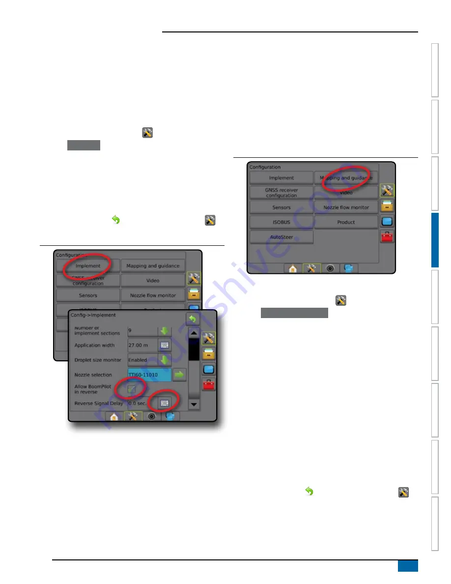
Reverse sense options are used when adding a Reverse sense
module or SCM Pro (Steering control module Pro for FieldPilot
Pro/UniPilot Pro) to any configuration.. This allows for application
mapping and control, and on-screen guidance when traveling in
reverse.
NOTE: For more information, see "Reverse sense" in the Implement
chapter of this manual.
1. Press CONFIGURATION side tab
.
2. Press
Implement
.
3. Select:
►Allow BoomPilot in reverse [when available] – used to enable
BoomPilot function while traveling in reverse
►Reverse signal delay – used to set the delay when going
from forward to reverse or reverse to forward, after which the
vehicle icon on a navigation screen changes direction
4. Press RETURN arrow
or CONFIGURATION side tab
to
return to the main Configuration screen.
Figure 4-11: Reverse sense
Mapping and guidance
Mapping and guidance options are used to configure the mapping
location, guidance width, guidance sensitivity (cross track error) and/
or an optional external lightbar module (ELM).
● Mapping and guidance [console only] – used to configure the
mapping location, guidance width and guidance sensitivity/
cross track error shown on the on screen guidance bar
● Mapping and guidance [using an external lightbar] – used to
configure an optional external lightbar module (ELM) which
provides additional guidance information.
Figure 4-12: Mapping and guidance
Mapping and guidance [console only]
1. Press CONFIGURATION side tab
.
2. Press
Mapping and guidance
.
3. Select:
►Mapping location – establishes the location from which the
boundary or polygon will be mapped.
● Default location – While creating an exterior boundary or
polygon, the line will be to the exterior of the outermost
active section. While creating an interior boundary, the line
will be to the interior of the innermost active section. If no
sections are active, the boundary will be marked to the end
of the outermost section.
● User entry – in-line and lateral offset from the GNSS
antenna directions and distances can be specified by the
user. Up to five (5) user entries can be created. See "User
entered mapping location" for details.
►Guidance width – used to set the distance between guidelines
►Guidance sensitivity – sets the distance around the guideline
that is perceived as zero error.
4. Press RETURN arrow
or CONFIGURATION side tab
to
return to the main Configuration screen.
Summary of Contents for AEROS 9040
Page 1: ...Software version 4 31 U S E R M A N U A L AEROS 9040...
Page 116: ......


