62
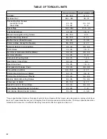
TABLE OF TORQUE LIMITS
INCH POUNDS
NEWTON METERS
Cylinder
80 - 100
9 - 11
Flywheel Nut
264 - 324
30 - 37
Connecting Rod Screws
Aluminum Rods
40 - 50
4.5 - 5.5
Steel Rods
70 - 80
8 - 9
Spark Plug
192 - 264
21.5 - 30
Fuel Tank Screws
12 - 20
1.5 - 2
Blower Housing Mounting Screws
80 - 100
9-11
Muffler Mounting Screws
80 - 100
9 - 11
Muffler Cover (Snowthrowers)
20 - 30
2 - 3.5
Stator to Base (Except Outboards)
80 - 100
9 - 11
External Screws to Laminations
30 - 40
3.5 - 4.5
Point Screw
15 - 25
1.5 - 3
Air Filter or Carburetor Baffle (Metal)
30 - 40
3.5 - 4.5
Air Filter (Plastic)
18 - 25
2 - 3
Carburetor Mounting Nuts
60 - 75
7- 8.5
Reed Plate, Cover Plate
35 - 45
4-5
Reed Hold down
15 - 25
1.5- 3
Compression Release Cover
30 - 40
3.5 - 4.5
Shroud Base to Block
80 - 100
9 - 11
Starter Mounting Screws (Metal)
50 - 70
5.5- 8
Starter Mounting Screws (Plastic)
30 - 40
3.5 - 4.5
Electric Starter Mounting Screws
65 - 85
7.5 - 9.5
Stop Lever to Head
80 - 100
9 - 11
Speed Control to Shroud Base
30 - 40
3.5 - 4.5
Compliance Brake Bracket to Cylinder
60 - 80
7 - 9
Compliance Brake Bracket to Base
35 - 50
4 -
5.5
"Torque specifications listed on this page should not be confused with the torque value observed on engines which have
been run. Torque relaxation occurs on all engines from thermal expansion and contraction. The torque specifications take
relaxation into account so a sufficient clamping force exists after an engine has been run.
Summary of Contents for AH520 -
Page 67: ...64...

