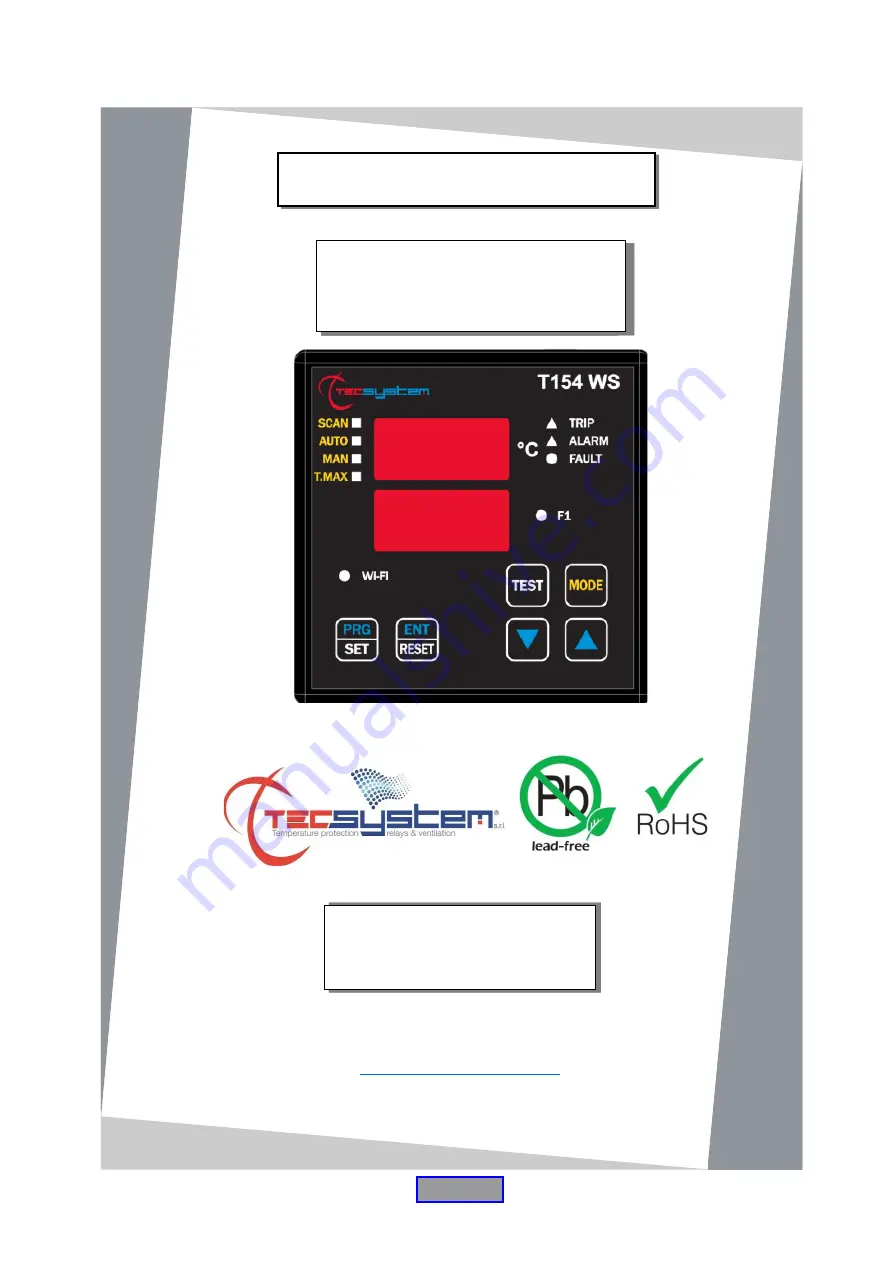
background image


     1MN0202 REV. 0 


operates with ISO9001 certified quality system 


http://www.tecsystem.it


                                                    R. 1.0 04/11/2020 


“Translations of the original instructions”


INSTRUCTION MANUAL 

T154 WS 

TECSYSTEM S.r.l.


20094 Corsico (MI) 

Tel.: +39-024581861 

Fax: +39-0248600783 


ENGLISH 


Summary of Contents for 1CN0247

Page 1: ...s with ISO9001 certified quality system http www tecsystem it R 1 0 04 11 2020 Translations of the original instructions INSTRUCTION MANUAL T154 WS TECSYSTEM S r l 20094 Corsico MI Tel 39 024581861 Fax 39 0248600783 ENGLISH ...

Page 2: ... PROGRAMMING NOTES 14 TEMPERATURE SENSORS 15 MEASUREMENT SIGNAL TRANSFER TEMPERATURE SENSOR DIAGNOSTICS 16 VOTING FUNCTION PROGRAMMED DATA DIAGNOSTICS TEMPERATURE DIAGNOSTICS 17 COOLING FAN CONTROL FAN TEST INTRODUCTION TABLE OF CONTENTS First of all we wish to thank you for choosing to use a TECSYSTEM product and we strongly suggest that you read this instruction manual carefully You will underst...

Page 3: ...WI FI CONNECTION 12 TECSYSTEM WEB SERVER 21 HOME SCREEN 22 TEMPERATURE AND ALARMS SCREEN SETTINGS SCREEN 23 NETWORK SETTINGS 24 OPTIONS 25 GRAPHICS SCREEN 26 EVENTS SCREEN 27 GRAPH DISPLAY NOTES 28 CSV FILE EXPORT NOTES PIN CODE 13 TROUBLESHOOTING 29 14 WARRANTY REGULATIONS 15 EQUIPMENT DISPOSAL 30 16 USEFUL CONTACTS ...

Page 4: ...ECTS Never insert any objects into the cracks of the control unit If this happens disconnect the control unit and contact an engineer USE RESERVED TO QUALIFIED PERSONNEL The purchased goods are a sophisticated electronic device that is totally unsuitable to be used by non qualified personnel Any work must be carried out by a specialist engineer ACCESSORIES The use of non original accessories or sp...

Page 5: ...orque 0 5Nm 1 relay terminal 10 poles pitch 5 Code 2PL0394 Screws tightening torque 0 5Nm 1 Terminal 12 poles pitch 3 81 sensors Pt100 Code 2PL0420 Screw tightening torque 0 25Nm 1 external Wi Fi SMA Antenna ACCESSORIES ATTENTION always install the device using the terminals included in the pack The use of terminals other than those included with the control unit might cause malfunctions ...

Page 6: ...ith 10A 250Vca res COSФ 1 contacts Wi Fi Connection protocol 802 11 b g n frequency 2 4 GHz with removable external antenna Max 100m in open field DIMENSIONS 100 x 100 mm DIN 43700 prof 150 mm including antenna installed at 90 C and terminal board Hole 92 x 92 mm TESTS AND PERFORMANCE Construction in compliance with the CE RED regulations Protection from electrical interference EN 61000 4 4 Dielec...

Page 7: ...FAN1 Temperature control from 0 C to 240 C 2 alarm thresholds for channels 1 2 3 2 alarm channels for channel 4 2 ON OFF thresholds FAN1 ventilation Sensor diagnostics Fcc Foc Fcd Data memory diagnostics Ech Access to programming through front keyboard Automatic exit from programming display and relay test after 1 minute of inactivity Incorrect programming warning Selection between channels automa...

Page 8: ... WI FI green LED 5 FAULT red LED 15 3 digit channel display 6 FAN 1 yellow LED 16 T max mode selection red LED 7 Display mode selection key 17 Man mode selection yellow LED 8 Fixing blocks 18 Auto mode selection green LED 9 UP key 19 Scan mode selection yellow LED 10 DOWN key 20 Fixing blocks FRONT PANEL 1 2 3 4 5 6 7 9 11 10 19 18 17 20 16 15 14 13 8 12 1MN0202 REV 0 ...

Page 9: ... the measurement circuit The temperature values displayed might be incorrect Return the control unit to TECSYSTEM for repairs 4 Pt Err This message appears when it is detected that one or more PT100 sensors are not working correctly FOC FCC and FCD indications in the temperature sensor diagnostics paragraph on page 16 In case of Err the FAULT relay will be de energised The above messages will be d...

Page 10: ...ly after suitably fixing the device 1 Control unit 2 Panel hole dimensions 0 8 mm tolerance 3 Identification label 1 Control unit 3 Locking screws 2 Fixing blocks 4 Cross head screwdriver 1X100mm ASSEMBLY Drill a hole in the panel sheet with dimensions of 92 x 92 mm 1 1MN0007 REV 0 2 3 1 2 3 4 1MN0008 REV 0 ...

Page 11: ...ac cc 50 60Hz 5 Antenna and Wi Fi connector 3 Relays FAN1 ALARM TRIP FAULT 1MN0095 REV 0 Output relay with contacts of 10A 250Vca res COSФ 1 COSФ 1 STOP SYSTEM INDICATION AUDIBLE AND VISUAL ALARM CONDITION Pt100 CONNECTION EXAMPLE Note before connecting the probes to the control unit carefully read the paragraph measurement signal transfer on page 15 1MN0202 REV 0 ELECTRICAL CONNECTIONS The Wi Fi ...

Page 12: ...itch when the set temperature thresholds are exceeded The FAULT fault contact programmed in active failsafe mode default YES opens 11 12 when the appliance is powered only if during the access phase the control unit does not detect anomalies and keeps the switching until when one of the following events occurs Data memory fault Ech message Pt100 sensor fault FCC short circuited sensor FOC interrup...

Page 13: ...fault YES 7 Select YES NO 8 The display shows CH4 Enabling CH4 9 Select YES or NO with YES the CH4 is enabled with NO the CH4 is disabled 10 The ALARM threshold for CH4 appears and the Alarm LED flashes If CH4 NO jump to step 16 Default NO 11 Set the desired threshold Default 120 C 12 The TRIP threshold for CH4 appears and the Trip LED flashes 13 Set the desired threshold Default 140 C 14 The disp...

Page 14: ...xit programming incorrect programming of the LED values indicated note 6 34 Return to step 1 PROGRAMMING NOTES 1 The MODE key allows reversing of the programming steps according to the sequence 28 26 8 1 2 The TEST key allows exiting programming without saving the modified data 3 After 1 minute s keyboard inactivity programming is abandoned without saving the data 4 During programming the control ...

Page 15: ...t only be earthed with a termination preferably on the control unit side 5 The sensors signal transfer cable must not be near electrical cables either low or medium high voltage 6 The Pt100 cable and the signal transfer cable must be laid in a straight line without any winding 7 Any caps used to butt conductors must be crimped properly to avoid false contacts NOTE to install the sensors and signal...

Page 16: ...ork Using the redundancy principle we use the sensors installed on the three phases U V W to monitor the transformer s operation and at the same time to ascertain the sensors are working correctly discriminating against any false alarms generated by installation errors By activating the VOTING YES function the control unit compares the temperature values recorded on the monitored CH1 CH2 CH3 chann...

Page 17: ...on the three columns CHF 1 2 3 e g ON at 70 C OFF at 60 C Through an additional probe CH4 YES dedicated to the ambient temperature inside the transformer room CHF 4 e g ON at 45 C OFF at 35 C The ON and OFF values are programmable according to the device range The FAN ON must always be at least 1 C higher than FAN OFF recommended Δ FAN ON_OFF 10 C The FAN 1 LED comes on when the temperature exceed...

Page 18: ...he pre set temperature limits are reached or as a result of no voltage FAULT By setting YES Fail safe contact 11 12 is positioned as normally open switches closed when a fault condition is identified see paragraph on alarms and ventilation on page 12 Setting NO NO Fail safe the contact 11 12 is positioned as normally closed switches open when a fault condition is identified see paragraph on alarms...

Page 19: ...raph on the measurement signal transfer on page 15 Identification of a sensor fault or faulty connection In case of a faulty connection or sensor fault a quick positive or negative variation in temperature might occur leading to the system tripping or the alarms of the monitored system to be triggered In this specific case we recommend the FCD function to be set in a temperature range of between 1...

Page 20: ...ires the insertion of a digital network key TECSYSTEM in the network key window repeat the operation in the network key confirmation window Click on CONNECT Once the connection is established your device will indicate Connected TECSYSTEM NOTE Connecting to the T154 WS network will result in automatic disconnection from other networks for devices such as Smartphones or Tablets it may be necessary t...

Page 21: ...MODBUS RUNNING ACCESS POINT NOTE in the Access point functions the device automatically keeps the date and time through a back up battery set at the first start up By accessing the Options page it will be possible to set the date time data manually see page 25 The data collected on the web server is divided into 6 screens Presentation screen Home Screen Temperatures and alarms screen Settings scre...

Page 22: ... F1 ALARM TRIP alarms HOME SCREEN The home screen allows the user to identify the cabin and to select the various screens The following information is shown in the management screen 1 Control unit model 6 GRAPHICS screen selection key 2 Station Name or monitored cabin 7 EVENT LOG screen selection key 3 Reference date 8 STATISTICS screen selection key Not available for the T154 WS model 4 Reference...

Page 23: ...he device will result in the display of an error POP UP window with the relative signalling the data update will not be processed Note PIN CODE settings and operation on page 28 16 17 Key BACK Return to the HOME screen 1 Channel reference and enabling CH1 CH2 CH3 and CH4 10 Enabling of FAILSAFE FUNCTION Relay ALARM TRIP FAULT 2 Enabling FAN 1 channel CH1 CH2 CH3 11 FAN 1 limit programming boxes On...

Page 24: ...e password 4 Subnet mask 7 Server NTP address automatic time and date update 1 Selection ACCESS POINT mode settings 8 Access Point SSID default TECSYSTEM network name modification 9 SSID password TECSYSTEM default SHOW to view the password After entering the PIN CODE default 00000 press SAVE to save the set values A POP UP window will confirm correct saving of data Note PIN CODE settings and opera...

Page 25: ... the PIN CODE default 00000 press SAVE to save the set values A POP UP window will confirm the correct saving of data Note PIN CODE settings and operation on page 28 1 2 3 4 5 6 7 8 9 10 11 12 13 The Web Access Credentials setting It is used to set username and a password Upon each log in to the web server a POP UP credential window will appear Set data time AP mode allows the user to manually set...

Page 26: ...ntify each recording in the graph Clicking on the individual point will show the information of channel date time and recorded temperature value Allows the user to set the graphical display period available in the following selections Last 24 hours Last 7 days Last 30 days The trend display channel temperatures will be updated according to the selection of the chosen period and the enabled channel...

Page 27: ...al time clock set to last saved Reset date and time automatic from the last saving W02 Real time clock manually set Manual date and time setting W03 Diagnostic button pressed The access point button has been pressed W04 TRIP temperature reached Reaching of the TRIP threshold on the identified CHn option screen enabling flag R00 Fcc off FCC OFF fault signal on CHn channel identified R01 Foc off FOC...

Page 28: ...te box up to 5 numbers SHOW to display the PIN CODE Press SAVE to save the pin A POP UP window will confirm correct saving PIN CODE default setting 00000 Press BACK to main page to return to the main screen GRAPH DISPLAY NOTES When opening the graphs page the last seven days recorded are displayed by default if seven days are not available in memory all the available data are displayed The time ra...

Page 29: ...more channels is wrong Contact the TECSYSTEM Technical Department Sudden trip of the main switch The temperature is on standard levels Just one channel has caused the trip Check the temperatures recorded in T MAX check the indications provided in the paragraphs transport of measurement signals and thermometric probe diagnostics on page 16 Activate the FCD function FCD warning See the FCD function ...

Page 30: ...uropean directive 2012 19 EU on electrical and electronic waste WEEE Any electrical or electronic equipment marked with this symbol must be disposed of separately from normal domestic waste Returning of used electrical appliances contact TECSYSTEM or the TECSYSTEM agent to receive information on correct disposal of the appliances TECSYSTEM is aware of the impact its products have on the environmen...

Reviews: