


P2002 Sierra
SECTION B
M A I N T E N A N C E M A N U A L
pag.
B-5
2
st
Edition, April 22
th
, 2008
INSPECTION & SERVICING
5
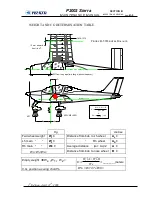
MOVING SURFACES CONTROL SETTINGS
Adjustment of control surfaces must not exceed travel limits reported in
table below.
5.1
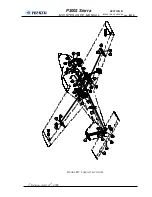
STABILATOR SETTING
In order to find the stabilator’s “zero” the aeroplane must be previously
longitudinally levelled. Place a shim 19mm thick over the stabilator’s rear
spar and place the level over the shim and the stabilator’s tubular spar (see
figure B-3), then level the stabilator.
F
IGURE
B-3
S
TABILATOR SETTING
5.2
TRIM-TAB ADJUSTMENT
The following procedure lists the operation to be carried out to adjust the
trim tab excursion:
•
Set the stabilator in its “zero” position and lock it in this position.
•
Turn the Master switch ON.
•
Trim to maximum pitch-up;
•
Adjust thread of hinged control rod until tab is deflected down-
wards 9° (use a protractor or measure downward displacement of
trailing edge - 9° is approximately 16mm);
•
Tighten lock-nut for adjustment thread and fasten connecting pin
of control rod to trim-tab.
AILERONS (starting from tip line-up)
up 25
o
dwn 19
o
±
1
o
STABILATOR
up 15
o
dwn 3
o
±
1
o
TRIM ( Stab. at 0
o
, see picture below)
2
o
9
o
±
1
o
RUDDER
Lh 30
o
Rh 30
o
±
2
o
FLAPS ( max. travel )
0
o
40
o
±
1
o
CONTROL CABLE TENSION (for all)
20 daN
±
2 daN